Part 3 Hull Chapter 13 Welding - Rules and standards - … groove angle made to ensure welding bead...
25
The content of this service document is the subject of intellectual property rights reserved by DNV GL AS ("DNV GL"). The user accepts that it is prohibited by anyone else but DNV GL and/or its licensees to offer and/or perform classification, certification and/or verification services, including the issuance of certificates and/or declarations of conformity, wholly or partly, on the basis of and/or pursuant to this document whether free of charge or chargeable, without DNV GL's prior written consent. DNV GL is not responsible for the consequences arising from any use of this document by others. The electronic pdf version of this document, available free of charge from http://www.dnvgl.com, is the officially binding version. DNV GL AS RULES FOR CLASSIFICATION Ships Edition October 2015 Amended January 2016 Part 3 Hull Chapter 13 Welding
Transcript of Part 3 Hull Chapter 13 Welding - Rules and standards - … groove angle made to ensure welding bead...
The content of this service document is the subject of intellectual property rights reserved by DNV GL AS ("DNV GL"). The useraccepts that it is prohibited by anyone else but DNV GL and/or its licensees to offer and/or perform classification, certificationand/or verification services, including the issuance of certificates and/or declarations of conformity, wholly or partly, on thebasis of and/or pursuant to this document whether free of charge or chargeable, without DNV GL's prior written consent.DNV GL is not responsible for the consequences arising from any use of this document by others.
The electronic pdf version of this document, available free of chargefrom http://www.dnvgl.com, is the officially binding version.
DNV GL AS
RULES FOR CLASSIFICATION
ShipsEdition October 2015
Amended January 2016
Part 3 Hull
Chapter 13 Welding

FOREWORD
DNV GL rules for classification contain procedural and technical requirements related to obtainingand retaining a class certificate. The rules represent all requirements adopted by the Society asbasis for classification.
© DNV GL AS October 2015
Any comments may be sent by e-mail to [email protected]
If any person suffers loss or damage which is proved to have been caused by any negligent act or omission of DNV GL, then DNV GL shallpay compensation to such person for his proved direct loss or damage. However, the compensation shall not exceed an amount equal to tentimes the fee charged for the service in question, provided that the maximum compensation shall never exceed USD 2 million.
In this provision "DNV GL" shall mean DNV GL AS, its direct and indirect owners as well as all its affiliates, subsidiaries, directors, officers,employees, agents and any other acting on behalf of DNV GL.

Part
3 C
hapt
er 1
3 C
hang
es -
cur
rent
Rules for classification: Ships — DNVGL-RU-SHIP-Pt3Ch13. Edition October 2015, amended January 2016 Page 3Welding
DNV GL AS
CHANGES – CURRENT
This is a new document.The rules enter into force 1 January 2016.Changes in this document are highlighted in red colour. However, if the changes involve a whole chapter,section or sub-section, normally only the title will be in red colour.
Amendments January 2016
• Sec.1 Design of weld joints— [2.4.5]: Clarified the symbols— [2.5.8]: Clarification
Editorial correctionsIn addition to the above stated changes, editorial corrections may have been made.
Part
3 C
hapt
er 1
3 C
onte
nts
Rules for classification: Ships — DNVGL-RU-SHIP-Pt3Ch13. Edition October 2015, amended January 2016 Page 4Welding
DNV GL AS
CONTENTS
Changes – current.................................................................................................. 3
Section 1 Design of weld joints.............................................................................. 51 General................................................................................................ 5
1.1 Application....................................................................................... 51.2 Alternatives......................................................................................61.3 Documents to be submitted...............................................................6
2 Tee or cross joint................................................................................ 62.1 Application....................................................................................... 62.2 Continuous fillet welds...................................................................... 62.3 Intermittent fillet welds.....................................................................72.4 Partial and full penetration welds........................................................82.5 Weld size criteria............................................................................ 10
3 Butt joint........................................................................................... 173.1 General..........................................................................................173.2 Thickness difference........................................................................17
4 Other types of joints......................................................................... 174.1 Lapped joints................................................................................. 174.2 Slot welds......................................................................................18
5 Connection details............................................................................. 195.1 Bilge keels..................................................................................... 195.2 End connections of pillars and cross-ties............................................20
6 Welding of rudders, rudder horns and rudder trunks.........................206.1 General..........................................................................................20
7 Welding of propeller nozzles............................................................. 227.1 General..........................................................................................23
8 Welding of sheer strake.................................................................... 238.1 General..........................................................................................23
9 Welding of outfitting details to hull...................................................239.1 General..........................................................................................23
10 Welding of aluminium alloys............................................................2410.1 General........................................................................................24

Part
3 C
hapt
er 1
3 Sec
tion
1
Rules for classification: Ships — DNVGL-RU-SHIP-Pt3Ch13. Edition October 2015, amended January 2016 Page 5Welding
DNV GL AS
SECTION 1 DESIGN OF WELD JOINTSSymbols
For symbols not defined in this section, refer to Ch.1 Sec.4.
Aweld = effective fillet weld area, in cm2
f = root face, in mmfweld = weld factorfyd = coefficient dependent on the material strength of the weld deposit:
fc = coefficient depending on the environment:
fc = 1.2 for liquid cargo tank, water ballast tank, hold for dry bulk cargo and bilge well
fc = 1.0 elsewhere
ℓdep = total length of deposit of weld metal, in mmℓ = leg length of continuous, lapped or intermittent fillet weld, in mmℓweld = length of the welded connection in mmReH_weld = specified minimum yield stress for the weld deposit in N/mm2, not to be less than:
ReH_weld = 355 for welding of normal strength steel with ReH = 235
ReH_weld = 375 for welding of high strength steels with ReH from 265 to 355
ReH_weld = 400 for welding of high strength steel with ReH = 390
τeH_weld = specified shear yield stress of weld deposit, in N/mm2
=
tas-built = as-built thickness of the abutting plate, in mmtgap = allowance for fillet weld gap is not to be taken less than 2.0 mm. Lower value may be accepted
based on a case-by-case considerationtthroat = throat thickness of fillet weld in mm, as defined in [2.5.3]k = material factor of the abutting member.
1 General
1.1 ApplicationThe requirements of this section apply to all ships, and cover the design of welded connections in hullstructures and are based on the requirements laid down in Pt.2.

Part
3 C
hapt
er 1
3 Sec
tion
1
Rules for classification: Ships — DNVGL-RU-SHIP-Pt3Ch13. Edition October 2015, amended January 2016 Page 6Welding
DNV GL AS
1.2 Alternatives
1.2.1 The requirements given in this section are considered minimum for electric-arc welding in hullconstruction, but alternative methods, arrangements and details will be specially considered for approval.
1.2.2 The minimum leg length limits given in Table 1 are to be complied with in all cases.
1.3 Documents to be submitted
1.3.1 The documents to be submitted are specified in Ch.1 Sec.3.
1.3.2 If welding consumables with deposit of the lower or higher yield strength than specified in Symbolsare used, the ReH_weld value shall be stated on the drawings submitted for approval. The yield strength of theweld deposit is in no case to be less than required in Pt.2 Ch.4.
2 Tee or cross joint
2.1 Application
2.1.1 The connection of primary supporting members, stiffener webs to plating as well as the platingabutting on another plating, are to be made by fillet or penetration welding, as shown on Figure 1.
Figure 1 Tee or cross joints
θ = connecting angle, in deg.
2.2 Continuous fillet welds
2.2.1 Continuous welding is to be used in the following locations:
a) Connection of the web to the face plate for all members.b) Boundaries of weathertight decks and erections, including hatch coamings, companionways and other
openings.c) Boundaries of tanks and watertight compartments.

Part
3 C
hapt
er 1
3 Sec
tion
1
Rules for classification: Ships — DNVGL-RU-SHIP-Pt3Ch13. Edition October 2015, amended January 2016 Page 7Welding
DNV GL AS
d) All structures inside tanks and cargo holds.e) Stiffeners and primary supporting members at tank boundaries.f) All structures in the aft peak and stiffeners and primary supporting members of the aft peak bulkhead.g) All structures in the fore peak.h) Welding in way of all end connections of stiffeners and primary supporting members, including end
brackets, lugs, scallops, and at perpendicular connections with other members.i) All lap welds in the main hull.j) Primary supporting members and stiffener members to bottom shell in the 0.3 L forward region.k) End connections of pillars.l) Hatch coaming stay webs to deck plating, see [2.4.4].
2.3 Intermittent fillet welds
2.3.1 Where continuous welding is not required, intermittent welding may be applied.
2.3.2 With reference to Figure 2, the various types of intermittent welds are as follows:
— chain weld— staggered weld— scallop weld (closed).
For size of welds, see [2.5].
Figure 2 Recommended arrangement of intermittent welds

Part
3 C
hapt
er 1
3 Sec
tion
1
Rules for classification: Ships — DNVGL-RU-SHIP-Pt3Ch13. Edition October 2015, amended January 2016 Page 8Welding
DNV GL AS
2.3.3 When chain and staggered welds are used on continuous members penetrating oil- and watertightboundaries, the weld termination towards the tank boundary shall be closed by a scallop, see Figure 3.Where intermittent welds are accepted, scallop welds shall be used in tanks for water ballast, cargo oil orfresh water.Chain, staggered and one side continuous fillet welds may be used in dry spaces and tanks arranged for fueloil only.
Figure 3 Weld termination towards tank boundary
2.3.4 Where beams, stiffeners, frames, etc., are intermittently welded and pass through slotted girders,shelves or stringers, there is to be a pair of matched intermittent welds on each side of every intersection. Inaddition, the beams, stiffeners and frames are to be efficiently attached to the girders, shelves and stringers.Where intermittent welding or one side continuous welding is permitted, double continuous welds are to beapplied for one-tenth of their shear span, in accordance with [2.5.2] and [2.5.3].
2.3.5 Size for one side continuous weldThe size for one side continuous weld is to be as required by [2.5.2] for intermittent welding, where f2 factoras defined in [2.5.2] is to be taken as 2.0.
2.4 Partial and full penetration welds2.4.1 Partial or full penetration weldingIn areas with high tensile stresses or areas considered critical, full or partial penetration welds are to beused.In case of full penetration welding, the root face is to be removed, e.g. by gouging before welding of the backside.For partial penetration welds the root face, f, is generally to be taken between 3 mm and tas-built /3.The groove angle made to ensure welding bead penetrating up to the root of the groove, α, is usually from40° to 60°, and is to be in accordance with recognised fabrication standard.The welding bead of the full/partial penetration welds is to cover the root of the groove.Examples of partial penetration welds are given in Figure 4.

Part
3 C
hapt
er 1
3 Sec
tion
1
Rules for classification: Ships — DNVGL-RU-SHIP-Pt3Ch13. Edition October 2015, amended January 2016 Page 9Welding
DNV GL AS
Figure 4 Partial penetration welds
2.4.2 One side partial penetration weldFor partial penetration welds with one side bevelling the fillet weld at the opposite side of the bevel shallsatisfy the requirements given in [2.5.2].
2.4.3 Extent of full or partial penetration weldingThe minimum extent of full or partial penetration welding is to be evaluated based on stress distribution inway of the reference point, i.e. intersection point of structural members, end of bracket toe, etc. In general,an extent of 300 mm from the reference point is acceptable.
2.4.4 Locations required for full penetration weldingFull penetration welds shall be used in the following locations:
a) Radiused hatch coaming plates in way of deck opening corners welded to the deck plate as shown inFigure 5.
b) Connection of vertical corrugated bulkhead to the lower hopper plate and to the inner bottom platewithin the cargo area, when the vertical corrugated bulkhead is arranged without a lower stool.
c) Connection of vertical corrugated bulkhead to top plating of lower stool.d) Edge reinforcement or pipe penetration both to strength deck, sheer strake and bottom plating within
0.6 L amidships, when the dimensions of the opening exceeds 300 mm, see Figure 5.e) Abutting plate panels with as-built thickness less than or equal to 12 mm, forming outer shell boundaries
below the scantling draught, including but not limited to: sea chests, rudder trunks, and portions oftransom. For as-built thickness greater than 12 mm, partial penetration in accordance with [2.4.1].
f) Crane pedestals and associated bracketing in way of end support, Ch.11 Sec.2 [4.4.2].g) Rudder horns and shaft brackets to shell structure.h) Rudder side plating to rudder stock connection areas.i) Upper connection of main vertical webs in spade rudders.
BUTT WELD
b
FULL PENETRATIONb > 300 mm
Figure 5 Deck and bottom penetrations
Full penetration welds may be required for other connections considered critical.

Part
3 C
hapt
er 1
3 Sec
tion
1
Rules for classification: Ships — DNVGL-RU-SHIP-Pt3Ch13. Edition October 2015, amended January 2016 Page 10Welding
DNV GL AS
2.4.5 Fillet welds and penetration welds subject to high tensile stressesIn case any penetration welding subject to high tensile stresses is used, the double continuous welding sizesshall not be less than:
where:
tp1, tp2 = weld connection in mm as defined in Figure 4
ften = welding factor subject to high tensile stresses:
=
η = yield usage factor for the connection:= σ/σperm
σ = calculated maximum tensile stress in abutting plate, in N/mm2
σperm = permissible stress of abutting plate according to the design load sets, in N/mm2
f = root face in mm, see Figure 4.
2.5 Weld size criteria
2.5.1 The required weld sizes are to be rounded to the nearest half millimetre.
2.5.2 The leg length, in mm, of continuous, lapped or intermittent fillet welds is not to be taken less than thegreater of the following values:
tleg as given in Table 1.
where:
tw = effective thickness of abutting plate in mmtw = tas-built for tas-built ≤ 25 mmtw = 0.5 (25 + tas-built) for tas-built > 25 mmtw = 25 + 0.25 (tas-built − 25) for longitudinals of flat-bar type with tas-built > 25 mmf1 = coefficient depending on welding type:
f1 = 0.30 for double continuous welding
f1 = 0.38 for intermittent welding
f2 = coefficient depending on the edge preparation
f2 = 1.0 for double continuous welding without bevellingf2 = min(f/tas-built + 0.35 ; 1.0) for partial penetration welds with one side bevelling
fweld = weld factor dependent on the type of the structural member, see Table 2 and Table 3f3 = correction factor for the type of weld:

Part
3 C
hapt
er 1
3 Sec
tion
1
Rules for classification: Ships — DNVGL-RU-SHIP-Pt3Ch13. Edition October 2015, amended January 2016 Page 11Welding
DNV GL AS
f3 = f0 for double continuous weld
f3 = sctr/ℓweld for intermittent or chain welding
sctr = distance between successive fillet welds, in mm, see Figure 6f0 = factor defined in [2.5.7].
2.5.3 The throat size tthroat, in mm, as shown in Figure 6, is not to be less than:
Figure 6 Weld scantlings definitions
Table 1 Minimum leg length
Minimum leg length, in mm
Plate thickness (web thickness), tw in mm Tanks, hold for dry bulkcargo and bilge well Elsewhere
tw ≤ 4.0 4.0 3.0
4.0 < tw ≤ 6.5 4.5 3.5
6.5 < tw ≤ 9.0 5.0 4.0
tw > 9.0 5.5 4.5
Part
3 C
hapt
er 1
3 Sec
tion
1
Rules for classification: Ships — DNVGL-RU-SHIP-Pt3Ch13. Edition October 2015, amended January 2016 Page 12Welding
DNV GL AS
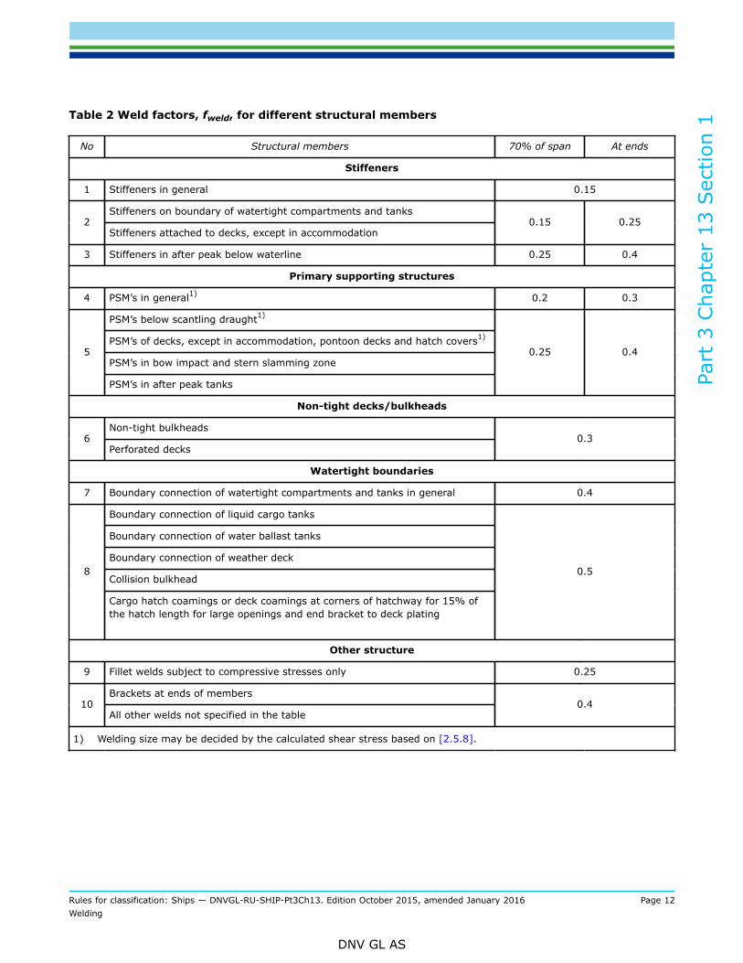
Table 2 Weld factors, fweld, for different structural members
No Structural members 70% of span At ends
Stiffeners
1 Stiffeners in general 0.15
Stiffeners on boundary of watertight compartments and tanks2
Stiffeners attached to decks, except in accommodation0.15 0.25
3 Stiffeners in after peak below waterline 0.25 0.4
Primary supporting structures
4 PSM’s in general1) 0.2 0.3
PSM’s below scantling draught1)
PSM’s of decks, except in accommodation, pontoon decks and hatch covers1)
PSM’s in bow impact and stern slamming zone5
PSM’s in after peak tanks
0.25 0.4
Non-tight decks/bulkheads
Non-tight bulkheads6
Perforated decks0.3
Watertight boundaries
7 Boundary connection of watertight compartments and tanks in general 0.4
Boundary connection of liquid cargo tanks
Boundary connection of water ballast tanks
Boundary connection of weather deck
Collision bulkhead8
Cargo hatch coamings or deck coamings at corners of hatchway for 15% ofthe hatch length for large openings and end bracket to deck plating
0.5
Other structure
9 Fillet welds subject to compressive stresses only 0.25
Brackets at ends of members10
All other welds not specified in the table0.4
1) Welding size may be decided by the calculated shear stress based on [2.5.8].

Part
3 C
hapt
er 1
3 Sec
tion
1
Rules for classification: Ships — DNVGL-RU-SHIP-Pt3Ch13. Edition October 2015, amended January 2016 Page 13Welding
DNV GL AS
2.5.4 Simplified calculation of weld factors for connection between stiffeners and primary supportmembers (PSM) for vessels with length L < 90 mThe size of fillet is to be calculated according to [2.5.2] based on the weld factors given in Table 3, whichmay be applied for ships with length less than 90 meters.
Table 3 Weld factors, fweld, for connection between stiffeners and PSM’s
ItemWeld factor
fweld
At tank boundary 0.4Primary supporting member web stiffener connection tointersecting stiffener Elsewhere 0.3
Without web stiffener on top of theintersecting stiffener 0.3
Shear connection inclusive lug or collar plateWith web stiffener on top of theintersecting stiffener 0.25
2.5.5 Welding size of connection between stiffeners and primary support members (PSM)The minimum leg length of welding for the connection between stiffener and primary supporting member isnot to be less than tleg given in Table 1 and [2.5.2] with weld factors fweld = 0.25.
The required welding size at stiffener connection to primary supporting members are not to be less than thevalues obtained from the following formula:
a) Shear connection inclusive of lug or collar plate:
b) PSM stiffener to intersecting stiffener:
where:
W1 = the load, in kN, transmitted through the shear connection as defined in Ch.6 Sec.7 [1.2.3]
W2 = the load, in kN, transmitted through the PSM stiffener as defined in Ch.6 Sec.7 [1.2.4]
τperm = permissible shear stress, in N/mm2, as defined in Ch.6 Sec.7 [1.2.4]
σperm = permissible nominal stress, in N/mm2, as defined in Ch.6 Sec.7 [1.2.4]
ℓs = total length of shear connection in mm, see Ch.6 Sec.7 Figure 2= ℓd + ℓc
dwc = total length of connection between the primary supporting member web stiffener/backingbracket and the stiffener in mm, see Ch.6 Sec.7 Figure 3
= dwc1 + dwc2
For the welding in way of the shear connection the size is not to be less than that required for the PSM webplate for the location under consideration.

Part
3 C
hapt
er 1
3 Sec
tion
1
Rules for classification: Ships — DNVGL-RU-SHIP-Pt3Ch13. Edition October 2015, amended January 2016 Page 14Welding
DNV GL AS
2.5.6 Welding factor for connection between stiffeners and primary supporting members (PSM)against bow impact and slamming pressureThe size of the fillet welds is to be calculated according to [2.5.2] with respect to bow impact and slammingpressure as given in Ch.10 Sec.1, Ch.10 Sec.2 and Ch.10 Sec.3 with the weld factor given below:
where:
W = load, in kN, as defined in Ch.10 Sec.1 [3.2.3]A1 = effective net shear area, in cm2, as defined in Ch.6 Sec.7 [1.2.3]
Aw = effective net cross sectional area, in cm2, as defined in Ch.6 Sec.7 [1.2.3].
2.5.7 Where the minimum weld size is determined by the requirements of second formula given in [2.5.2],the weld connections to shell, decks or bulkheads are to take account of the cut out, where stiffeners passthrough the member. In cases where the width of the cut-out exceeds 20 % of the stiffener spacing, the sizeof weld leg length is to be adjusted by a factor equal:
where:
s = stiffener spacing in mm, as shown in Figure 7ℓw = length of web plating between notches, in mm, as shown in Figure 7.
Figure 7 Effective material in web cut-outs for stiffeners
2.5.8 End connection of primary supporting membersThe weld connection area of bracket to adjoining girders or other structural parts shall be based on thecalculated normal and shear stresses. Double continuous welding shall be used.
The section modulus of the weld area at the end connection of simple girders shall satisfy the requirement forsection modulus given for the girder in question.

Part
3 C
hapt
er 1
3 Sec
tion
1
Rules for classification: Ships — DNVGL-RU-SHIP-Pt3Ch13. Edition October 2015, amended January 2016 Page 15Welding
DNV GL AS
Welding of the end connections, inclusive 10% of shear span, of primary supporting members is to be suchthat the weld area is to be equivalent to the gross cross sectional area of the member. The weld leg length, inmm, ℓ is to be taken as:
where:
hw = web height of primary supporting members, in mmtgr_req = required gross thickness of the web in way of the end connection, in mmℓweld = length of the welded connection in mm, as shown in Figure 8ℓdep = total length of deposit of weld metal, in mm, taken as:
ℓdep = 2 ℓweld
The size of weld is not to be less than the value calculated in accordance with [2.5.2].
Where high shear stresses occur in web plates at end connection (inclusive 10% of shear span), doublecontinuous fillet welds shall have weld leg length, in mm, not less than:
τ = calculated average shear stress in web plate in way of the weld, in N/mm2
Ct = permissible shear stress coefficient for the design load set being considered, as given in Ch.6 Sec.6Table 2.

Part
3 C
hapt
er 1
3 Sec
tion
1
Rules for classification: Ships — DNVGL-RU-SHIP-Pt3Ch13. Edition October 2015, amended January 2016 Page 16Welding
DNV GL AS
Figure 8 Shear area of primary supporting member in way of weld
2.5.9 Longitudinal continuity provided by bracketsWhere a longitudinal strength member is cut at a primary supporting structure and the continuity of strengthis provided by brackets, tleg is not to be less than the requirement given in [2.4.5], [2.5.2] and [2.5.10]
2.5.10 Reduced weld sizeWhere an approved automatic deep penetration procedure is used and quality control facilitates are workingto a gap between members of 1 mm and less, the weld factors given in Table 2 may be reduced by 15%but not more than fillet weld leg size of 1.5 mm. Reductions of up to 20%, but not more than the fillet weldleg size of 1.5 mm, will be accepted provided that the Shipyard is able to consistently meet the followingrequirements:
a) The welding is performed to a suitable process selection confirmed by welding procedure tests coveringboth minimum and maximum root gaps.
b) The penetration at the root is at least the same amount as the reduction into the members beingattached.
2.5.11 Reduced weld size documentationWhere any of the methods for reduction of the weld size are used, the specific conditions for the reductionare to be specified on the drawings. The drawings are to document the weld design and dimensioningrequirements for the reduced weld length and the required weld leg length given by [2.5.2] without the leglength reduction. The drawings shall also describe the difference in the two leg lengths and their application.

Part
3 C
hapt
er 1
3 Sec
tion
1
Rules for classification: Ships — DNVGL-RU-SHIP-Pt3Ch13. Edition October 2015, amended January 2016 Page 17Welding
DNV GL AS
3 Butt joint
3.1 General
3.1.1 Joints in the plate components of stiffened panel structures are generally to be joined by butt welds,see Figure 9.
Figure 9 Typical butt welds
3.1.2 Butt welding from one side against permanent backing or without backing will only be permitted afterspecial consideration, and for locations where the stress level is considered low. Such welding shall not beused inside tanks.
3.2 Thickness difference3.2.1 TaperIn the case of welding of plates with difference in as-built thickness equal to or greater than 4 mm, thethicker plate is normally to be tapered. The taper has to have a length of not less than 3 times the differencein as-built thickness. If the width of groove is greater than 3 times the difference in as-built thickness thetransition taper may be omitted.
4 Other types of joints
4.1 Lapped joints4.1.1 AreasLap joint welds may be adopted in very specific cases, such as for the following connections:
— Peripheral connections of doublers.
Part
3 C
hapt
er 1
3 Sec
tion
1
Rules for classification: Ships — DNVGL-RU-SHIP-Pt3Ch13. Edition October 2015, amended January 2016 Page 18Welding
DNV GL AS
— Internal structural elements subject to very low stresses.
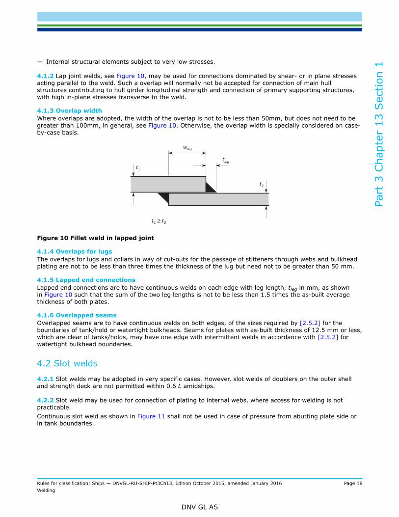
4.1.2 Lap joint welds, see Figure 10, may be used for connections dominated by shear- or in plane stressesacting parallel to the weld. Such a overlap will normally not be accepted for connection of main hullstructures contributing to hull girder longitudinal strength and connection of primary supporting structures,with high in-plane stresses transverse to the weld.
4.1.3 Overlap widthWhere overlaps are adopted, the width of the overlap is not to be less than 50mm, but does not need to begreater than 100mm, in general, see Figure 10. Otherwise, the overlap width is specially considered on case-by-case basis.
Figure 10 Fillet weld in lapped joint
4.1.4 Overlaps for lugsThe overlaps for lugs and collars in way of cut-outs for the passage of stiffeners through webs and bulkheadplating are not to be less than three times the thickness of the lug but need not to be greater than 50 mm.
4.1.5 Lapped end connectionsLapped end connections are to have continuous welds on each edge with leg length, tleg in mm, as shownin Figure 10 such that the sum of the two leg lengths is not to be less than 1.5 times the as-built averagethickness of both plates.
4.1.6 Overlapped seamsOverlapped seams are to have continuous welds on both edges, of the sizes required by [2.5.2] for theboundaries of tank/hold or watertight bulkheads. Seams for plates with as-built thickness of 12.5 mm or less,which are clear of tanks/holds, may have one edge with intermittent welds in accordance with [2.5.2] forwatertight bulkhead boundaries.
4.2 Slot welds
4.2.1 Slot welds may be adopted in very specific cases. However, slot welds of doublers on the outer shelland strength deck are not permitted within 0.6 L amidships.
4.2.2 Slot weld may be used for connection of plating to internal webs, where access for welding is notpracticable.Continuous slot weld as shown in Figure 11 shall not be used in case of pressure from abutting plate side orin tank boundaries.

Part
3 C
hapt
er 1
3 Sec
tion
1
Rules for classification: Ships — DNVGL-RU-SHIP-Pt3Ch13. Edition October 2015, amended January 2016 Page 19Welding
DNV GL AS
6 – 10 mm15°
Figure 11 Filled up continuous slot welds
4.2.3 Slot weld is not acceptable in areas with high in-plane stresses transversely to the slots.
4.2.4 Slots are to be well-rounded and have a minimum slot length, ℓslot of 75 mm and width, wslot of twicethe as-built plate thickness. Where used for doublers, such welds are in general to be spaced a distance,sslot of 2 ℓslot to 3 ℓslot but not greater than 250 mm, see Figure 12. The size of the fillet welds is to bedetermined from second formula given in [2.5.2] using tas-built and a weld factor fweld = 0.40.
Figure 12 Slot welds
5 Connection details
5.1 Bilge keels
5.1.1 The ground bar is to be connected to the shell with a continuous fillet weld, and the bilge keel to theground bar with a continuous fillet weld in accordance with Table 4. The leg length shall not be less than theminimum leg length as given in Table 1 and the first formula given in [2.5.2].

Part
3 C
hapt
er 1
3 Sec
tion
1
Rules for classification: Ships — DNVGL-RU-SHIP-Pt3Ch13. Edition October 2015, amended January 2016 Page 20Welding
DNV GL AS
Table 4 Connections of bilge keels
Leg length of weld, in mmStructural items being joined
At ends Elsewhere
Ground bar to the shell 0.60 t1as_built 0.45 t1as_built
Bilge keel web to ground bar 0.50 t2as_built 0.30 t2as_built
t1as-built = as-built thickness of ground bar, in mm
t2as-built = as-built thickness of web of bilge keel, in mm.
5.1.2 Butt welds, in the bilge keel and ground bar, are to be well clear of each other and of butts in the shellplating. In general, shell butts are to be flush in way of the ground bar and ground bar butts are to be flushin way of the bilge keel. Direct connection between ground bar butt welds and shell plating is not permitted.This may be obtained by use of removable backing.
5.1.3 At the ends of the ground bar, the leg length thickness is to be increased as given in Table 4, withoutexceeding the as-built thickness of the ground bar. The welded transition at the ends of the ground bar to theplating connection shall be formed with the weld flank angle of 45 deg or less.
5.1.4 In general, scallops and cut-outs are not to be used. Crack arresting holes are to be drilled in the bilgekeel butt welds as close as practicable to the ground bar. The diameter of the hole is to be greater than thewidth of the butt weld and not less than 25 mm. Where the butt weld has been subject to non-destructiveexamination, the crack arresting hole may be omitted.
5.2 End connections of pillars and cross-ties5.2.1 Pillars and cross-ties exposed to tensile stressWhen pillars and cross-ties are exposed to tensile stress, an effective fillet weld area in cm2, i.e. weld throatmultiplied by weld length, shall not be less than:
where:
F = maximum tensile design force in kN. The actual design force corresponding to the differentacceptance criteria to be used without correction factor, the acceptance criteria is covered by the Cp
Cp = Coefficient for design tensile force= 1.0 for AC-I= 1.25 for AC-II and AC-III.
6 Welding of rudders, rudder horns and rudder trunks
6.1 General
6.1.1 Welds between plates and heavy pieces (solid parts in forged or cast steel or very thick plating) shallbe made as full penetration welds. In way of highly stressed areas e.g. cut-out in semi-spade rudder andupper part of spade rudder, cast or welded ribs shall be arranged. Two sided full penetration welding shall

Part
3 C
hapt
er 1
3 Sec
tion
1
Rules for classification: Ships — DNVGL-RU-SHIP-Pt3Ch13. Edition October 2015, amended January 2016 Page 21Welding
DNV GL AS
normally be arranged. Where back welding is impossible welding shall be performed against ceramic backingbar or equivalent. Steel backing bars may be used and shall be continuously welded on one side to the heavypiece.
6.1.2 In spade rudders, the weld connection of the main vertical webs to the rudder top plate shall be of fullpenetration type.
6.1.3 The weld at the connection between the rudder horn plating and the side shell is to be full penetration.The welding radius is to be as large as practicable and may be obtained by grinding.
6.1.4 Vertical webs and horizontal webs in effective area of rudder as defined in Ch.14 Sec.1 [6.3.2], shallbe connected to the side plates with continuous fillet weld in accordance with [2.5.2]. Weld factor fweld to beused is 0.40.
6.1.5 Slot welding shall be limited as far as possible. Slot welding is not acceptable in areas with high inplane stresses transversely to the slots or in way of cut-out areas of semi-spade rudders. Continuous buttwelding with backing might be accepted in lieu of slot welds. When continuous butt welding is applied, theroot gap is to be between 6-10 mm. The bevel angle is to be at least 15°, see Figure 11.When slot welding is applied, minimum length of slots is 75 mm and minimum breadth is 2·tas-built, where tas-built is the as built rudder plate thickness in mm. The distance between the slots is not to be greater than 125mm. The slots are to be fillet welded around the edges and filled with a suitable compound, e.g. epoxy putty.Slots as shown in Figure 12 shall not be filled with weld.
6.1.6 In way of the rudder horn recess of semi-spade rudders the radii in the rudder plating are not to beless than 5 times the plate thickness, but in no case less than 100 mm. Welding in side plate is to be avoidedin or at the end of the radii. Edges of side plate and weld adjacent to radii are to be ground smooth.
6.1.7 Plate edges at openings in rudder side plating shall be ground smooth. Cover plates shall be arrangedwith rounded corners and are not to be welded directly to cast parts.
6.1.8 The weld at the connection between the rudder trunk and the shell or the bottom of the skeg isnormally to be full penetration. Partial penetration welds against ceramic backing will be accepted, see Figure13.
The fillet shoulder radius, in mm (see Figure 13) is to be as large as practicable and to comply with thefollowing formulae:
r = 60 when σ ≥ 40 / k [N/mm2]
r = 0.1dc, without being less than 30 when σ < 40 / k [N/mm2]
where:
dc = rudder stock diameter axis in mm, as defined in Ch.14 Sec.1 [4.1.2]σ = bending stress in the rudder trunk in N/mm2
k = material factor as given in Ch.14 Sec.1 [1.6.2] or Ch.14 Sec.1 [1.6.6] respectively.
The radius may be obtained by grinding. If disk grinding is carried out, score marks are to be avoided in thedirection of the weld. The radius is to be checked with a template for accuracy. Four profiles at least are to bechecked. A report is to be submitted to the Surveyor.
Rudder trunks comprising of materials other than steel are to be specially considered by the Society.
Part
3 C
hapt
er 1
3 Sec
tion
1
Rules for classification: Ships — DNVGL-RU-SHIP-Pt3Ch13. Edition October 2015, amended January 2016 Page 22Welding
DNV GL AS
Figure 13 Fillet shoulder radius
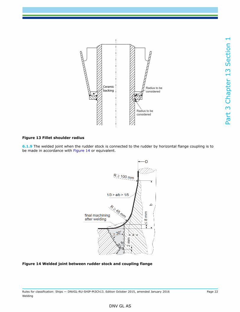
6.1.9 The welded joint when the rudder stock is connected to the rudder by horizontal flange coupling is tobe made in accordance with Figure 14 or equivalent.
Figure 14 Welded joint between rudder stock and coupling flange
Part
3 C
hapt
er 1
3 Sec
tion
1
Rules for classification: Ships — DNVGL-RU-SHIP-Pt3Ch13. Edition October 2015, amended January 2016 Page 23Welding
DNV GL AS
7 Welding of propeller nozzles
7.1 General
7.1.1 The inner shell plate shall be welded to the ring webs with double continuous fillet welding.
7.1.2 The outer shell plate is as far as possible to be welded continuously to the ring webs. Slot welding maybe accepted on the following conditions:If the web spacing s ≤ 350 mm all welds to outer plating may be slot welds. If the web spacing s > 350 mmat least two ring webs shall be welded continuously to the outer shell. A continuous weld as shown in Figure11 may be accepted.
8 Welding of sheer strake
8.1 General8.1.1 WeldingThe sheer strake may be either welded to the stringer plate or rounded.Longitudinal weld seams of rounded sheer strake are to be located outside the bent area at a distance notless than 5 times the as-built thicknesses of the sheer strake.The upper edge of the welded sheer strake is to be rounded smooth and free of notches.Welded sheer strake is to be connected to strength deck by partial or full penetration welds according to[2.4]. For plate thickness less than 25 mm, fillet welds are permitted.
8.1.2 Deck fittingsFixtures such as bulwarks and eye plates are not to be directly welded on the upper edge of sheer strake,except within 0.1 L from A.E. and F.E., for ship with length L ≥ 90m. Drainage openings with a smoothtransition in the longitudinal direction may be permitted.The design of the fittings shall be such as to minimise stress concentrations, with a smooth transitiontowards deck level.For vessels with low/moderate hull girder stress, such details will be considered on a case-by-case basis.
8.1.3 Rounded sheer strakeWelding of deck fittings to rounded sheer strakes shall be kept to a minimum within 0.6 L amidships. Subjectto special consideration, such welding may be carried out provided:
— when cold formed, the material is of grade D or higher— the material is hot formed in accordance with Ch.3 Sec.5 [2.5].
9 Welding of outfitting details to hull
9.1 General
9.1.1 Generally connections of outfitting details to the hull shall be such that stress concentrations areminimised and welding to highly stressed parts is avoided as far as possible.Connections shall be designed with smooth transitions and proper alignment with the hull structure elements.Terminations shall be supported.
9.1.2 Equipment details as clips for piping, support of ladders, valves, anodes etc. shall be kept clear of thetoe of brackets, edge of openings and other areas with high stresses.

Part
3 C
hapt
er 1
3 Sec
tion
1
Rules for classification: Ships — DNVGL-RU-SHIP-Pt3Ch13. Edition October 2015, amended January 2016 Page 24Welding
DNV GL AS
Connections to top flange of girders and stiffeners shall be avoided if not well smoothened. Preferablysupporting of outfittings shall be welded to the stiffener web.
9.1.3 All materials welded to the hull shell structure shall be of ship quality steel, or equivalent, preferablywith the same strength group as the hull structure the item is welded to.
9.1.4 Gutterway bars on strength deck shall be arranged with expansion joints unless the slendernessrequirements given in Ch.8 Sec.2 [2] are fulfilled.
9.1.5 Welds to the deck plating within the hatch corner region are to be avoided as far as possible.
9.1.6 Requirements for welding of outfitting details for container ships are given in Pt.5 Ch.2 Sec.10 [3.2.4].
10 Welding of aluminium alloys
10.1 General
10.1.1 The welding of aluminium alloys are to be in accordance with rules for High Speed, Light Craft andNaval Surface Craft, HSLC Pt.3 Ch.3.

DNV GLDriven by our purpose of safeguarding life, property and the environment, DNV GL enablesorganizations to advance the safety and sustainability of their business. We provide classification andtechnical assurance along with software and independent expert advisory services to the maritime,oil and gas, and energy industries. We also provide certification services to customers across a widerange of industries. Operating in more than 100 countries, our 16 000 professionals are dedicated tohelping our customers make the world safer, smarter and greener.
SAFER, SMARTER, GREENER


![[PPT]WELDING · Web view... QW461 Performance Qualification Position & Dia Limits- QW461.9 Performance Qualification Groove-Weld, Pipe Dia. Limits QW 452.3 Welding Variables- Qw 416](https://static.fdocuments.us/doc/165x107/5b09886b7f8b9a992a8dd19a/ppt-view-qw461-performance-qualification-position-dia-limits-qw4619-performance.jpg)