PART 2 HANDLING List of Chapters Chapter
28
AP 101B-4401-15 Third Edition PART 2 HANDLING List of Chapters Chapter STARTING, TAXYING AND TAKE OFF … … … … … 1 HANDLING IN FLIGHT … … … … … … … … 2 CIRCUIT PROCEDURE AND LANDING … … … … … 3
Transcript of PART 2 HANDLING List of Chapters Chapter

AP 101B-4401-15 Third Edition
PART 2
HANDLING
List of ChaptersChapter
STARTING, TAXYING AND TAKE OFF … … … … … 1
HANDLING IN FLIGHT … … … … … … … … 2
CIRCUIT PROCEDURE AND LANDING … … … … … 3

Intentionally Blank

AP 101B-4401-15 Third EditionStarting, Taxying And Take Off
PART 2
CHAPTER 1 - STARTING, TAXYING AND TAKE OFF
ContentsPara
General
1. The checks referred to in this chapter are listed in the Flight Reference Cards (FRC)
WARNING 1: Ensure the MASS in the front cockpit is set to LOCK SAFE at all times except from just beforetake-off to immediately after landing.
WARNING 2: The aircraft ejection seats and the MDC system are a potential source of danger since theirinadvertent operation can cause fatal injuries. Safety precautions are therefore to be observed at all times,ie, the aircraft is to be left in the Safe for Parking or Safe for Maintenance condition, as applicable, asdefined below:
a. Safe for Parking. Safety pins are to be fitted to the ejection seat firing handle, the MDC firing unitand the canopy MDC firing handle in each cockpit.
b. Safe for Maintenance. In addition to the safety pins fitted under sub-para a, safety pins are alsoto be fitted to the ejection seat main gun sear, rocket initiator sear and the manual separation firing unitsear in each cockpit.
Preparation for Flight
2. Approaching the aircraft carry out the Approaching The Aircraft Checks. Check that the aircraft is SafeFor Parking as in WARNING 2 above, then carry out the Initial, External and Ejection Seat Checks. If theaircraft is to be flown solo, carry out the Solo/Rear Seat Flight Checks. Then carry out the Internal Checks.
Starting the Engine
3. Before starting:
a. The aircraft should be heading into wind; with the tail facing into wind a hotter than normal start mayresult.
b. Access steps are to be removed and the canopy is to be closed and locked.
4. Start the engine in accordance with the Engine Starting Checks. Control of the starting system isautomatic except for the initiation of the air producer start cycle and the engine start selection. Manualcancellation can be effected at any time during the cycle.
5. Engine light up normally occurs within 10 seconds of moving the throttle lever to Idle. During the startthe TGT increases rapidly at first, but the rate of increase should reduce when the TGT rises above about350LC; the highest TGT normally reached is about 400LC. If the starting TGT limit is rapidly approached andappears likely to be exceeded, set the throttle to HP Off. Monitor TGT and RPM during the start cycle.
General… … … … … … … … … 1Preparation for Flight … … … … … … … 2Starting the Engine … … … … … … … 3Failure to Start… … … … … … … … 10Checks After Starting … … … … … … … 13Taxying … … … … … … … … … 14Take-Off Procedures … … … … … … … 17Engine Failure After Take-Off … … … … … 23
2 - 1Page 1 (AL 1)

WARNING: With the throttle at the Idle stop, when selecting HP Off the throttle lever has first to be easedforward fractionally (3 to 5 mm) from the stop to ensure that the throttle lever catch is fully disengaged beforefinal aft movement of the throttle past the stop. This is particularly important when the rear cockpit throttlelever is used.
6. The air producer shuts down automatically if 82% air producer RPM is not attained within 30 seconds ofpressing the start/relight button; automatic shutdown also occurs, following a start, when the engine reachesstarter motor cut-out speed (approximately 45%). If 45% RPM are not attained within 45 seconds fromselecting the engine start master switch to START, the air producer decelerates to, and remains running at,idle.
7. During engine starting, No 2 hydraulic pump remains off loaded, and the fuel pump is powered from theEssential Services busbar.
8. Note the engine idle RPM and TGT, open the throttle slowly to approximately 65% to close the bleedvalve and, after observing a small drop in TGT, reselect Idle. Confirm bleed valve closure by noting anincrease in idle RPM of approximately 3% and a decrease in TGT of approximately 50LC. To reduce thepossibility of HP compressor blade damage, do not delay closure of the bleed valve.
9. Whilst operating on No 1 hydraulic system and before operating HYD 2 reset button, move the controlcolumn in a circle of approximately 2 inches diameter (measured at the top of the hand grip) about neutral ata rate of less than one cycle per second. A minimum of four complete circles is to be carried out to ensurethat control surface response and control column feel are satisfactory.
Failure to Start
10. If the engine fails to start at the first attempt, refer to the Starting Failures Checks. Before makingfurther attempts, check all relevant switches and indications. If the ROTATION indicator does not show greenduring the air producer start cycle, ignition is unlikely to occur.
11. Allow three minutes between air producer start cycles to avoid air producer starter motor overheat, andan interval of 20 minutes after three consecutive cycles. After three unsuccessful air producer start attemptshave the cause investigated.
12. If it is necessary to stop the air producer or cancel the start cycle at any time, select the engine startmaster switch to OFF and the throttle to HP Off.
Checks After Starting
13. Carry out the After Start Checks.
Taxying
14. Carry out the Taxying Checks. Release the parking brake and increase the RPM up to approximately70% to start the aircraft moving. As the aircraft moves forward, check the brakes. The brakes are veryeffective and should therefore be applied progressively. To prevent overheating, avoid excessive use of thebrakes; the high idling thrust, however, may require the use of the brakes to maintain a slow taxying speedbut avoid `riding' the brakes as this may lead to loss of servo pressure inducing an apparant brake failure.
15. Differential braking gives good directional control, and the fully castoring nosewheel allows the aircraftto be turned in a very small radius if necessary. The view from both cockpits is good to the front and sides,and both wingtips can easily be seen. Providing no hard turning movements are carried out, idle RPM issufficient to maintain taxying speed on level ground. The fuel consumption at idle is approximately 3 kg perminute.
16. Carry out the Before Take-Off Checks. A tailplane indicator setting of zero is satisfactory for the cleanaircraft. However, at high masses (ie, with fuselage and wing stores) or at forward centre of gravity (CG) (eg,two heavy pilots) a setting of 1L nose-up gives a more comfortable control column load during the post-take-off acceleration. Post-SEM 122, when carrying the sled, set 1L nose-up. If asymmetric stores are carried,
2 - 1Page 2

AP 101B-4401-15 Third EditionStarting, Taxying And Take Off
both aileron and rudder should be trimmed towards the light store: aileron half deflection, rudder one thirddeflection, as seen on the respective trim gauges.
WARNING: The aircraft is not to be flown if a surge, stall or overtemperature occurs. If the T6NL caption isilluminated during engine starting or at any other time on the ground, a take-off is not to be attempted, evenif the warning has extinguished.
Take-Off Procedures
17. Normal Take-Off.
a. The normal configuration for take-off is with the flaps set to MID.
b. Align the aircraft on the runway with the nosewheel straight, and fully apply the wheelbrakes withthe rudder bar central. Hold the aircraft on the wheelbrakes and open the throttle, checking that thebrakes are holding and that the maximum values of RPM and TGT are not exceeded (refer to HawkTMk1 & TMk1A MOD AFD Release to Service).
Note: With new brake pads fitted the brakes may not hold against full throttle until after they have beenbedded in on the initial landing run. Therefore, this check may not be possible for the first take-off afterfitting new brakes.
c. Release the brakes. Keep straight with rudder using differential braking if necessary until the rudderbecomes effective, typically at about 50 knots. There are now two take9off technique options that can beapplied.
(1) Option 1. At 90 knots move the control column aft in order to raise the nosewheel just off therunway. The minimum speed at which nosewheel lift off (NWLO) can be achieved varies withaircraft mass and CG position. At aft CG very little aft control column movement is required to raisethe nosewheel at 90 knots, consequently stick forces are light. At forward CG the minimum NWLOspeed is increased and at extreme forward CG the application of full aft control column displacementmay not raise the nosewheel until about 110 knots. When Sidewinder missiles are carried increasethe NWLO speed to 100 knots; the aircraft is particularly sensitive in pitch in this configurationespecially at aft CG.
(2) Maintain the nosewheel off attitude until 120 knots is reached, then fly off by easing the controlcolumn further aft to rotate to the take-off attitude. If the rotation is delayed a slight hopping fromone main wheel to the other results, especially if the nose attitude is unduly high. In the short periodbetween rotation speed and unstick speed the forward view from the front cockpit is good but theview from the rear cockpit is restricted by the windscreen arch; however, there is ample view oneither side of the nose to allow directional control to be maintained. With external stores fitted delayrotation until 130 knots.
(3) Option 2. At 120 knots, smoothly ease the control column aft to the take off attitude. Withexternal stores fitted, delay rotation to 130 knots.
d. When safely airborne retract the landing gear and flaps, observing speed limitations; trim changesare negligible.
18. Maximum Performance Take-Off.
a. Proceed as for a normal take-off. At Vr (obtained from the ODM) firmly and smoothly rotate to a 10Lnose-up attitude. At extreme forward CG the increased minimum NWLO speed may result in thenosewheel lift-off and the take-off rotation merging into one continuous attitude change. Maintain the10L nose-up attitude and retract the landing gear. When clear of all obstacles, retract the flaps.
b. The maximum rate of rotation is limited by pre-stall buffet. Avoid rotation beyond the onset of buffetsince it may increase the take-off distance to clear 50 feet.
2 - 1Page 3 (AL 3)

c. When carrying Sidewinder missiles with a forward aircraft CG, take care to avoid rotation andunstick below the speeds given in the ODM as the margin between the stalling speed and the unstickspeed is reduced.
19. Flapless Take-Off. If a take-off is made with the flaps up, raise the nosewheel off the runway at 100knots (if required) or smoothly ease the stick aft at 130 knots to hold the take9off attitude. The aft controlcolumn displacement required to raise the nosewheel is very small and stick forces are therefore minimal; apositive check forward may be required to prevent over-rotation. The take-off is appreciably longer and, afterunstick, the acceleration is more rapid than normal, consequently take care not to exceed the landing gearlimiting speed.
20. Crosswind Take-Off. In crosswind conditions there is no tendency for the aircraft to lean out of windduring the ground roll. Raise the nosewheel at 90 knots. Some into-wind aileron may be necessary at unstickto maintain wings level. On becoming airborne, centralize the rudder and control column and allow theaircraft to adopt a crabbed attitude.
21. Take-Off With Towed Banner Target. With a towed banner target make a normal take-off but raisethe nosewheel at 100 knots (if required) and unstick at 130 knots. It is recommended that the crosswindcomponent should not exceed 15 knots for runways up to 150 feet wide nor exceed 20 knots for runwayswider than 150 feet.
22. Abandoned Take-Off.
a. If a take-off is abandoned on the ground, the brakes may be applied at any speed. If mass is morethan 5000 kg and braking is commenced at more than 110 knots the brakes are subsequently to beinspected for distortion and wear.
b. To abandon a take-off set the throttle to Idle, commence the emergency braking technique(Chapter 3) and then lower the flaps fully. If an overrun or barrier engagement appears likely, select HPOff to eliminate the high idling thrust of the engine. In an overrun situation consider emergency retractionof the landing gear or ejection. When the aircraft has stopped, set the LP cock to OFF (if appropriate),the battery switches to off and make the aircraft Safe for Parking.
Note 1: The use of emergency braking causes high temperatures at the brakes and the aircraft shouldnot be taxyed subsequently.
Note 2: Maximum take-off abort speeds (ie, Vstop) are given in AP 101B-4401-16 (Hawk Operating DataManual).
Engine Failure After Take-Off
23. An engine failure after take-off (EFATO) can be defined as an engine failure at any point from unstick upto 300 knots.
24. There are three possible situations in this context where engine failure can occur:
a. Unstick Until Landing Gear Selected UP. If the engine fails between unstick and the moment thelanding gear is selected UP, the aircraft may be abandoned or, if the aircraft is only just airborne, anattempt to land ahead on the remaining runway may be made. Due to the large number of variables thataffect the landing run the decision as to whether a safe landing ahead is possible can only be made bythe pilot on the day. Take-off and landing data are available in AP 101B-4401-16 (Hawk Operating DataManual).
b. Landing Gear Selected UP to 250/270 Knots. If the engine fails between the time the landing gearis selected UP and 250 knots (clean and/or gun and/or pylons) or 270 knots (aircraft with non-jettisonablewing stores), abandon the aircraft.
c. Between 250/270 and 300 Knots. If the speed is between 250/270 and 300 knots commence aturnback to the airfield. However, a turnback to the reciprocal of the runway in use is to be carried outwith extreme caution because of the hard manoeuvring which would be required.
2 - 1Page 4

AP 101B-4401-15 Third EditionStarting, Taxying And Take Off
Note: Above 300 knots the failure should not be considered an EFATO; the pilot may position for anysuitable runway.
25. The minimum speeds in para 24c and the Note above do not guarantee a successful turnback andsafe landing; they merely ensure that the pilot is in a position to assess the situation and make a timelyejection decision if necessary.
26. The principal considerations that influence the decision are set out below, but the main factorsdetermining the success of a turnback are twofold: firstly, the ability to make a prolonged turn whilstmaintaining the minimum gliding speed and avoiding buffet, and secondly, the ability to land and stop theaircraft safely, even with the assistance of a barrier. The former is relatively easy to achieve but the latter isfar more difficult.
27. A 20-knot tailwind, which could well be encountered, extends the landing ground run by about 45%beyond the zero wind situation. The ground run is extended again by an average 85% on a wet runway.Crosswinds above 10 knots extend the ground run by a further 15%, and landing above the correct thresholdspeed adds 10% per 5 knot increment.
28. Finally, the fact that the engine may not even be windmilling and therefore producing no extra HYD 1system pressure may limit the amount of braking and steerage that can be maintained. The barrier arreststhe aircraft but in the process extends up to 400 feet (T Mk 1 at 5000 kg) or 450 feet (T Mk 1A at 5550 kg)at, for example, an entry speed of 110 knots.
29. If in doubt whether a safe barrier engagement can be made, do not delay the ejection decision; there isa minimum safe distance from the barrier that ejection can be initiated. It is essential to bear in mind theability to stop when carrying out the pre take-off emergencies brief.
30. Considerations. The chances of a successful turnback are affected by the following:
a. Factors Affecting the Manoeuvre
(1) Where two pilots are carried, which one is to fly the manoeuvre.
(2) Height, position and speed at which the failure occurs.
(3) Aircraft configuration and whether stores are jettisonable.
(4) Position of other aircraft which might conflict with the turnback.
(5) Cloudbase and visibility.
(6) Wind velocity.
b. Factors Affecting Ejection Decision
(1) Command ejection selector lever on or off.
(2) Position of buildings, ASPs, public roads, and personnel.
c. Factors Affecting Chances of a Safe Landing
(1) The length of the runway and the braking action.
(2) The touchdown point and speed.
(3) Availability of a barrier, and the length and nature of the safe overrun.
(4) Tail and crosswind components.
(5) The lack of full braking potential if the engine is not running to supply HYD 1 pressure.
2 - 1Page 5

31. Turnback Manoeuvre - Initial Actions. Following an EFATO, jettison stores if appropriate and set thethrottle to HP Off. Climb and turn towards the selected runway.
32. Turnback Manoeuvre - Subsequent Actions. Make a brief radio call and concentrate on flying anaccurate turn. Maintain 180 knots and aim to intercept the flightpath for an aiming point one third of the wayalong the runway. Once this is achieved, lower the landing gear on the normal and then the standby systemsand maintain 170/175 knots. If time permits, switch off the fuel pump and close the LP cock. When certainof reaching the aiming point lower the flaps on the normal and then the standby systems to bring thetouchdown point nearer the threshold and maintain a minimum speed of 150 knots until the landing flare.
33. Intercepting PFL Pattern. Anticipate a late intercept of the PFL pattern. The approach is likely to beflown with a tailwind component and with an aircraft that is relatively heavy. Maintain the correct speeds andmake an early decision to eject if necessary.
WARNING: If speed falls below 170/175 knots when gliding flapless with landing gear down, the high rate ofdescent and limited margin above pre-stall buffet make it doubtful whether a successful roundout can becompleted.
2 - 1Page 6

AP 101B-4401-15 Third EditionHandling In Flight
PART 2
CHAPTER 2 - HANDLING IN FLIGHT
ContentsPara
Illustrations Fig
ENGINE CONTROL AND HANDLING
Engine Control
1. Basic control of the engine is by the pilot's throttle lever which manually positions the throttle valve in thefuel control unit to vary the fuel flow and hence thrust. The fuel flow as scheduled by the throttle valve iscompensated for variations in altitude and forward speed. To prevent the engine exceeding its maximumtemperature, pressure and shaft speeds, automatic controls and governors reduce the scheduled fuel flow ifmaximum engine conditions are reached. Operation of the automatic controls and governors is effected byone of the four following parameters according to the flight conditions:
ENGINE CONTROL AND HANDLINGEngine Control… … … … … … … … 1Engine Handling … … … … … … … 4Engine/Airframe Vibration … … … … … … 9Thrust Pulsation … … … … … … … 15Engine Icing … … … … … … … … 16
GENERAL HANDLINGGeneral… … … … … … … … … 18Climbing … … … … … … … … 19Flying Controls… … … … … … … … 20Changes of Trim … … … … … … … 23Flying at High Mach Number… … … … … … 28Unaccelerated Low Speed Handling … … … … 33Stalling In Manoeuvre… … … … … … … 41Stalling in the Final Turn or on Final Approach … … … 43Spinning … … … … … … … … 44Rapid Rolling … … … … … … … … 50Aerobatics … … … … … … … … 51Low Speed Recovery Drill … … … … … … 55Practice Low-Speed Nose-High Recoveries … … … 57Formation Flying … … … … … … … 60Flying with Asymmetric Stores … … … … … 63Instrument Flying … … … … … … … 64Night Flying … … … … … … … … 66Descending … … … … … … … … 67Gliding … … … … … … … … … 68Forced Landings - Gliding Performance … … … … 69Flying in Turbulence … … … … … … … 72Operating in Icing Conditions … … … … … 73
TARGET TOWINGGeneral… … … … … … … … … 74Towed Banner Target Release … … … … … 75Malfunctions - Banner Target Towing … … … … 76
Approximate Regions of Engine Limiters (Maximum Rating - ISA Conditions) … … … … … … … … 1Stalling Speeds … … … … … … … 2
2 - 2Page 1 (AL 3)

a. TGT.
b. LP shaft speed (NL).
c. HP shaft speed (RPM).
d. Fuel flow.
2. Fig 1 shows the approximate regions of engine limiters at maximum rating, ISA conditions. The limitingregions change with ambient temperature; the TGT limited region decreases at temperatures below ISA andincreases at temperatures above ISA.
Note: On Fig 1, HP shaft speed (RPM) is referred to as NH.
3. During take-off at full throttle at ambient temperatures above approximately minus 5LC, the engine isTGT limited; at ambient temperatures below approximately minus 5LC, the engine is NL limited. During climbat full throttle, the engine is TGT, NL or fuel flow limited depending upon the altitude, ambient temperatureand mach number. When the engine is NL limited or fuel flow limited the TGT and RPM are reduced frommaximum, eg, at maximum power and minus 5LC, sea level static conditions, there is a reduction ofapproximately 20LC TGT and 0Q9% RPM.
Engine Handling
4. Unless in emergency, the engine is not to be shut down from a high power setting.
5. Although slam and re-slam accelerations up to maximum thrust are permitted up to 0Q90M/550 knots,pop surges may occur during slams above 40,000 feet at high incidence. An audible surge may also occurwhen the throttle is opened at high altitude/low IAS if high incidence or sideslip is present; under theseconditions, however, warning of entry to the surge-prone area is given by the onset of pre-stall buffet.Immediate throttling back to Idle should clear the surge; TGT should then be closely monitored and the TGT/RPM relationship verified as normal to ensure that the surge has not `locked in'. In severe cases of surgethe throttle is to be set to HP Off.
6. The minimum speed for engine relighting using the unassisted relight technique is determined bymaximum permitted TGT. An attempt to carry out an unassisted relight below the recommended speed of250 knots will probably cause the TGT to exceed the temperature limit.
7. Following an engine surge or a relight, and after recovering from a spin, prove the engine for surge-freeoperation by opening the throttle and checking that the increase in RPM leads the increase in TGT. If theengine is locked in surge the TGT increases rapidly at low RPM values.
8. During recoveries from the climbing vertical the engine is to be at idle RPM. After recovery the engineis to be monitored for surge-free operation.
WARNING: Aircraft UHF transmissions from the ARC 164 transceiver in the frequency band 225 to 399Q975MHz using the lower aerial may cause a reduction of maximum engine RPM by up to 2% and could lead tospurious T6NL warnings. When the transmission ceases, full fuel flow is restored rapidly and could causeengine surge.
Engine/Airframe Vibration
9. Certain combinations of engine RPM and altitude can cause engine vibration accompanied by noiselevel changes; both effects are perceptible in the cockpit. The amplitude of the vibration and the noise levelcan, at their worst, be considerable and the onset sudden. Although the vibration is not damaging in the shortterm and thus pilots may become accustomed to it with experience, the condition should he avoided since avibration resulting from an engine malfunction may be incorrectly diagnosed as a `normal' vibration withpotentially serious consequences. As vibration may also arise from airframe sources, the cause of vibrationwhen experienced should be diagnosed if possible and the flight conditions adjusted or the sortie terminated,depending on the nature, severity and persistence of the vibration.
2 - 2Page 2

AP 101B-4401-15 Third EditionHandling In Flight
10. Possible causes of airframe vibration are the cold air unit, flap vanes, RAT (when extended) and thenosewheel doors. Vibration caused by the cold air unit is similar, both in noise and amplitude, to enginevibration and diagnosis should be effected, if height and other considerations permit, by switching the unitoff. Flap vane vibration is recognized by a high frequency oscillation or buzzing which occurs at or near themid-flap position. Nosewheel door vibration with the landing gear retracted, is proportional to IAS and istherefore easily recognized as airframe rather than engine in nature.
11. Engine vibration, at heights below about 30,000 feet, is apparent in the form of a mild rumbling andnormally occurs between 85% and 95% RPM; it may be most marked at or close to 93% RPM. Avoidsustained operation in this RPM band when vibration is encountered.
12. As altitude is increased the level of engine vibration tends to increase and the band of engine speed inwhich it occurs widens; the peak amplitude however remains at or near 93% RPM. At 44,000 feet the bandmay extend from 80% to 98% RPM. Since when climbing at full throttle the RPM slowly decreases, the onsetof vibration may be abrupt as the decreasing RPM enters the widening band; the onset may be sharp andaccompanied by a small drop in RPM (about 0Q3%). It is recommended that, if marked vibration isencountered in a full throttle climb, the climb be discontinued. If the throttle is left in its set position and speedincreased the vibration ceases as the aircraft descends through the onset altitude.
13. If the RPM setting is reduced when operating at high altitude and outside the vibration RPM band theonset of vibration may be abrupt as the band is entered.
14. The amplitude of vibration and noise varies from aircraft to aircraft and day to day but the onset levelsand RPM bands are repeatable during a single flight.
Thrust Pulsation
15. Pre-Mod 646, thrust pulsation may occur at any altitude when the engine is operating at full throttle. Itis felt by the pilot as an oscillation in thrust. Between 10,000 and 35,000 feet the oscillation is quite fast butproduces no readable changes in RPM or TGT; above 35,000 feet the oscillation is slow and changes of 0Q2%RPM and 5LC TGT may be indicated. Flight in the thrust pulsation condition should be avoided; ifencountered it can be eliminated by closing the throttle sufficiently to reduce engine RPM slightly.
Note: Occasionally the aircraft rocks fore-and-aft when held at full throttle on the brakes before take-off butthis is acceptable.
Engine Icing
16. Engine icing may occur when the ambient temperature is plus 6LC or less, together with a relativehumidity of 50% or more. Although the LP compressor nose fairing is continuously anti-iced, there is no anti-icing protection for the air intakes or for the airframe. It is therefore recommended that flight in icingconditions be avoided.
17. If icing conditions exist at take-off the ground running times are to be kept to a minimum. If icing isencountered in flight, climb or descend out of icing conditions as quickly as possible at the highest practicableRPM. Normal engine handling may be used, but it is recommended that, after an inadvertent icing encounter,engine response be checked before landing.
GENERAL HANDLING
WARNING: The IAS/Mach limits given in the Hawk TMk1 & TMk1A MOD AFD Release to Service are basedpurely on structural considerations. No adverse handling characteristics have been encountered up to themaximum permitted speeds. Without external stores the aircraft is virtually self-limiting, but with externalstores, particularly at medium altitudes, the IAS/Mach limits can easily be exceeded in a shallow dive.Consequently, take care not to exceed the stated limits when carrying out aerobatics or air combatmanoeuvres at medium altitudes.
2 - 2Page 3 (AL 3)
General
18. The controls are light and precise, and the aircraft is very responsive throughout its speed range butparticularly at high speeds. The forward view from both cockpits is good but the rearward view is restrictedby the fuselage and ejection seat.
Climbing
19. The recommended climbing speed without wing stores is 350 knots converting to 0Q73M, using maximumRPM within the engine limitations. When wing stores are carried, the recommended climbing speed is 300knots converting to 0Q65M.
Flying Controls
20. Ailerons. The gearing between (lateral) stick and aileron is approximately linear and independent ofapplied lateral trim. Artificial feel is provided by a simple spring, giving light stick forces that are independentof speed. In flight, if the stick is left free, the aileron circuit will respond slightly to both lateral and longitudinalaccelerations, but the forces that are required to compensate for these effects are so light as to beunnoticable to the pilot. Aircraft roll acceleration and damping are high. Above 350 knots some light buffetmay be felt during full aileron rolls. The maximum rate of roll is achieved at about 400 knots at low level, butabove this speed roll rate is reduced by compressibility and aero-elastic effects. With wing stores fitted, therate of roll is slightly reduced.
21. Tailplane. In the tailplane circuit there is a non-linear gearing between the stick and the control surfacewhich gives small tailplane deflections per unit stick deflection around stick central, but significantly increasedtailplane movements as the forward and aft stick limits are reached. The gearing is effectively independentof applied tailplane trim. Artificial feel is provided by a two9rate spring (increased stick force with stickdisplacement, assuming no re-trimming) and an inertia weight mounted in the forward fuselage (increasingstick force with G and pitch acceleration). Stick forces are generally light to moderate; manoeuvring to Genvelope limits at high Mach numbers is characterised by increased pitch sensitivity if stores are carried.
22. Rudder. The gearing between pedals and rudder is approximately linear. Rudder pedal forces areprimarily a function of rudder aerodynamic hinge moments (the circuit also includes a light spring) and henceare light at low speeds, becoming progressively heavier as speed increases. Rudder trim is applied througha simple trim tab. Application of rudder produces a useful roll response at moderate to high incidences; rollresponse is significantly lower at low incidence (unless flaps are deployed), and above 300kts, may be in anadverse sense. When carrying Sidewinder missiles the application of full rudder should be avoided at speedsabove 300 knots as rudder buffet can occur and the sideslip limit may be exceeded.
Changes of Trim
23. Flaps. Lowering the flaps to MID at about 150 knots causes a small but easily controlled nose-up trimchange; at 200 knots the effect is more marked. Lowering full flap produces an additional nose-up trimchange; when the flaps are fully down there is slight airframe buffeting. Raising the flaps results in negligibletrim changes but the inadvertent raising of the flaps on an approach would result in the loss of approximately300 feet even with full RPM applied immediately.
24. Landing Gear. Lowering the landing gear causes a small nose-down movement, except when the flapsare down when the movement is nose-up; the trim changes are, however, negligible. Retraction producesno noticeable effects.
25. Airbrake. Trim changes following airbrake operation are insignificant below 350 knots/0Q60M. Asspeed is increased the trim changes increase and, in general, are more marked on extension than onretraction. In all cases, a large nose-down transient change is followed by a small residual nose-downchange.
26. RPM. Changes of RPM setting cause negligible trim changes.
27. Acceleration and Deceleration. As speed is increased up to approximately 350 knots, nose-downtrimming is required to maintain level flight; some directional trimming may also be necessary. Between 350
2 - 2Page 4

AP 101B-4401-15 Third EditionHandling In Flight
and 450 knots however, trim changes are negligible. At higher speeds the nose drops slightly and trimmingis again required. At the higher speeds longitudinal control becomes sensitive. During decelerations therequired trim changes are reversed, becoming more pronounced in the low airspeed range.
Flying at High Mach Number
28. General. The speed limitations are to be observed. The handling and behaviour of the aircraft at highmach number varies with altitude, incidence and sideslip; the following description, for an aircraft withoutstores, is given to indicate the behaviour likely to be encountered.
29. Transonic Flight. At full throttle the maximum speed obtainable in level flight is approximately 0Q87M.In level flight the transonic envelope starts at about 0Q78M, and is characterized by the onset of light buffetfollowed by a slight nose-down trim change between about 0Q80 and 0Q82M. At higher speeds longitudinalcontrol becomes more sensitive.
30. Transonic Dives. A dive angle of about 20L or more is required to give a supersonic mach number.Trim the aircraft at 0Q75M before entering the dive and maintain this trim setting throughout.
a. As speed increases through 0Q78M, slight buffeting may be felt, increasing noticeably at 0Q85M.Above about 0Q92M, buffeting is not present.
b. Following the nose-down trim change between 0Q80 and 0Q82M, the aircraft develops small, randompitch movements in the range 0Q86 to 0Q90M due to shock wave formation; above 0Q90M the randompitch movements damp out. A further nose-down trim change occurs at about 0Q95M.
c. Between 0Q88 and 0Q94M a wing heavy tendency develops, which can be easily controlled usingabout one-half aileron deflection; above 0Q94M the tendency disappears. If the ailerons are used at thehigher mach numbers, at low incidence values, some roll reversal may be apparent at very small aileronangles.
CAUTION: In the transonic region the aircraft exhibits increased longitudinal control sensitivity. When this iscombined with the pitch changes associated with selecting the airbrake out, a pilot-induced oscillation,characterised by rapid development of a longitudinal divergent oscillation, may occur. If oscillation occurs,smoothly close the throttle to Idle and release the control column; the aircraft then recovers. Below 0Q90M,replace the hand on the control column and re-establish control.
31. Transonic Dive Recovery. The accelerometer is to be monitored throughout the dive recovery. Toprevent excessive g, the recovery from a transonic dive is to be initiated with a pull to not more than 2Q5 g.During the recovery two significant nose-up trim changes occur: the first at 0Q98M is followed by a sharpereffect at 0Q94M. The trim changes are to be countered by moving the control column forward to attempt tomaintain 2Q5 g; however, excursions beyond can be expected. If a pilot-induced oscillation occurs, smoothlyclose the throttle to Idle and release the control column; the aircraft then recovers. Below 0Q90M replace thehand on the control column and re-establish control.
32. Wing Stores. With wing stores fitted, the flight characteristics up to 0Q90M are broadly similar to thosedescribed in para 30 and para 31. However, the stores are destabilizing in pitch, and the random pitchmotion which develops between 0Q86 and 0Q90M is likely to be more severe.
Unaccelerated Low Speed Handling
33. General. The unaccelerated low speed behaviour of the aircraft is docile; the aircraft is fully controllabledown to the point of stall (CL max), beyond the stall it may be possible to control the attitude of the aircraft,but not the flightpath, using co-ordinated control. The stall itself is not obvious but recovery at all stages isimmediate when the control column is eased forward. The low speed handling characteristics for the threebasic configurations are given below. The speeds quoted are for an aircraft without stores and at a mass of4600 kg; some scatter in these speeds occurs with stores and centre of gravity (CG) position as describedin para 37.
34. Clean Configuration, Flaps and Landing Gear Up. The first indication of an approaching stall is theonset of buffet at about 130 knots. As speed is decreased (Angle of Attack (AOA) increased) buffet increases
2 - 2Page 5 (AL 3)
and some slight lateral unsteadiness develops which is easily controlled with ailerons. At the stall a gentlewing drop may occur and a high sink rate develops if nose-up pitch is not markedly increased. The basicstalling speed is about 124 knots but this varies slightly depending on the rate of deceleration. If the aircraftis flown beyond the stall by moving the control column further aft some yaw may develop which causes atendency to roll; check the yaw with rudder. The ailerons alone may not be adequate to control the roll if theyaw is not checked. At approximately 115 knots with the control column fully aft, the aircraft has an increasedtendency to yaw and roll. If the control column is held fully back the aircraft descends at a high sink rate butwith the airspeed increasing; pitch oscillations may occur.
35. Flaps and Landing Gear Down.
a. A nominal engine setting of 80% RPM simulates an intermediate approach and is suitable forpractice with MID flap. With MID flap selected the onset of buffet is at about 113 knots. As speed isdecreased (AOA increased) the aircraft behaviour is similar to that described above for the cleanconfiguration down to the point of stall at about 109 knots. Beyond the stall there is less tendency forthe aircraft to yaw. With the control column held fully aft the sink is more pronounced and the aircraftdevelops a moderate pitching oscillation.
b. An engine setting of 80% RPM can be used to simulate approach thrust and is suitable for practicewith FULL flap. With FULL flap selected the low speed characteristics are similar to those with MID flapexcept that there is less warning of the stall and a greater tendency to oscillate in pitch. The onset ofbuffet is at about 105 knots and the stall at about 102 knots. At about 99 knots, with the control columnfully aft, a pitch oscillation may develop into a combined pitch and roll oscillation which cannot becontrolled; recovery from this stage is likely to result in a large height loss.
Note: In the event of flight with flap fully down but with the landing gear up, particularly at high altitudeor with a forward CG position, an uncontrollable pitch nose down may occur. In this event control canimmediately be restored by either selecting landing gear down or flap up.
36. Airbrake. Low speed handling characteristics with the airbrake extended are little different from thoseof a clean aircraft except that the buffet level is increased and tends to mask the buffet onset as speed isdecreased (AOA increased) towards the stall.
37. Effect of Stores. With wing stores, the low speed handling characteristics are similar to thosedescribed above. However, there may be some slight variation in stalling speeds associated with variationsin CG position and stores configuration. As speed is decreased (AOA increased) beyond the stall the wingstores, particularly with flap down, tend to amplify the pitch oscillation with FULL flap. The oscillation is moremarked than with MID flap.
38. Effect of Altitude. As altitude is increased, lateral unsteadiness becomes more pronounced butremains controllable with aileron. At high altitudes (towards 40,000 feet) speeds may be one or two knotshigher than described above.
39. Recovery. Recovery at any stage is immediate upon moving the control column forward. However, tominimise height loss, which is imperative if the stall occurs when the aircraft is slow speed and near to theground (eg during the Final turn), the Standard Stall Recovery should be conducted. The Standard StallRecovery is flown by simultaneously moving the control column forward and applying full power and rollingwings level. Once out of the stall, smoothly select a climbing attitude, taking care not to re-stall the wing.When a positive rate of climb is achieved, select gear and flap to UP.
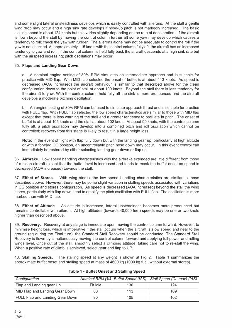
40. Stalling Speeds. The stalling speed at any weight is shown at Fig 2. Table 1 summarizes theapproximate buffet onset and stalling speed at mass of 4600 kg (1000 kg fuel, without external stores).
Table 1 - Buffet Onset and Stalling Speed
Configuration Nominal RPM (%) Buffet Speed (IAS) Stall Speed (CL max) (IAS)Flap and Landing gear Up Flt idle 130 124MID Flap and Landing Gear Down 80 113 109FULL Flap and Landing Gear Down 80 105 102
2 - 2Page 6

AP 101B-4401-15 Third EditionHandling In Flight
Stalling In Manoeuvre
41. The amount of pre-stall buffet warning in manoeuvre increases with mach number. In the cleanconfiguration the buffet boundary is very clear and provides a good natural warning of the stall at all altitudes.The stall characteristics are variable with mach number but may take the form of a wing drop, a pitchingoscillation (sometimes preceded by a small movement in yaw), or by the control column reaching the fully aftposition. Below about 0Q40M, the buffet onset approximates to the maximum turning performance of theaircraft. Recovery is immediate on easing the control column forward.
42. The carriage of wing stores increases the severity of the pre-stall buffet and makes the aircraft moreprone to pitching oscillations at the stall. The characteristics are otherwise similar to those of the unladenaircraft.
Stalling in the Final Turn or on Final Approach
43. During the final turn or on final approach, particularily with MID or FULL flap selected, there is limitednatural warning of the onset of the stall. At the first onset of buffet carry out the standard stall recovery.
WARNING: Continuing beyond the initial onset of buffet may rapidly result in a stall, the consequences ofwhich will result in significant, and possibly irrecoverable, height loss.
Spinning
44. General. The aircraft is very spin resistant and is therefore reluctant to enter a spin inadvertently;however, it can be made to spin by the use of recommended techniques. Provided these techniques areadhered to, the spin characteristics are consistent; if the controls are mishandled the characteristics vary andthe spin may become very agitated. If the spin is allowed to become severely agitated or oscillatory, there isa risk of engine surge. The aircraft will recover when the recommended spin recovery action of centralizingthe controls is taken.
45. Normal Erect Spin.
a. Entry. For the most consistent spin behaviour characteristics, the recommended entry to a normalerect spin is from a level turn with between 30L and 45L bank angle, at a speed of 160 to 170 knots andat an altitude between FL250 - FL300. A spin may also be entered from level flight at 150 knots in thesame altitude band; however, if the speed is significantly less than 150 knots (eg, 130 knots) there is arisk of engine surge. To enter the spin, close the throttle, smoothly and progressively apply full rudderin the intended direction of the spin and simultaneously apply full aft stick ensuring that the aileronsremain neutral.
b. Spin Characteristics. The first turn of the spin is slow, but the rate of rotation increases as thespin develops, and stabilizes at about 4 seconds per turn. Height loss in the stabilized spin is 800 to1500 feet per turn. The spin attitude is fairly steep with the nose about 55L below the horizon. Airspeed,which decreases to about 130 knots on entry, increases progressively by about 10 knots per turn. Theairspeed and TGT should be monitored throughout the spin, and recovery is to be initiated before 180knots is reached (fin loading consideration). During the developed spin there is considerable rudderbuffet and increasing rudder forces may blow the rudder off the stop.
WARNING: If recovery (ie, rotation ceased, speed increasing and the aircraft responding normally to thecontrols) has not been achieved by 5000 feet AGL - Eject.
c. Spin Recovery. To recover from a spin, monitor the height, check the throttle is closed andsmoothly centralize the controls. As the aircraft incidence reduces, the rate of rotation increasesmomentarily and some sideslip may be experienced as the rotation ceases. Recovery is effected withinone or two turns. Height loss during recovery may be up to 2500 feet, with a further 4000 feet in theensuing dive, using 3Q5 g. Note that the aircraft recovers from an erect spin if the controls are abandonedbut this technique is not recommended since aircraft behaviour is less predictable and often physicallyunpleasant and may lead to disorientation. Following recovery check the engine for surge.
2 - 2Page 7 (AL 3)
46. Spinning with Stores. Although the aircraft is not cleared for deliberate spinning with external storesfitted, other than a gun pod, flight tests have shown that the carriage of stores does not change the generalspin characteristics and recovery. However, the attitude in the spin is slightly steeper, the rate of rotationhigher, and the height loss per turn greater. Jettisoning of stores in the spin is not recommended.
47. Engine Behaviour. TGT is to be monitored during spinning, and a precautionary check is always to bemade after spin recovery to ensure that the engine is surge free. An engine surge may be experienced if anagitated spin develops, particularly if the entry altitude is above the recommended band or the RPM settingis above idle at entry. The surge is unlikely to be audible unless the engine is at a high RPM setting. TheTGT may rise rapidly or remain only a little above normal until the throttle is opened on recovery. Therefore,following recovery, a positive check is to be made that TGT and RPM rise normally as the throttle is opened.If an engine surge occurs during the spin, spin recovery action is to be taken immediately and the throttle setto HP Off.
48. Inverted Spin. Deliberate inverted spinning is prohibited. Tests indicate that recovery is immediate oncentralizing the controls. During an inverted spin aerodynamic forces move the rudder in the pro-spindirection. A positive effort is therefore required to centralize the rudder for recovery; the rudder forces maybe high.
49. Mishandling the Controls. If an oscillatory spin develops through mishandling, normal spin recoveryaction is always effective. If a spin develops through mishandling, recovery action is to be taken immediatelyand the TGT checked for engine surge indications. Engine surge is more likely if the spin motion causes theairspeed to fall below 100 knots.
a. Effect of Mishandling at Spin Entry.
(1) Application of Full Rudder Before Aft Stick. If the roll rate is allowed to develop before thestick is moved aft, the application of aft stick causes the roll rate to slow down; the spin thenbecomes hesitant with fluctuations in sideslip, roll rate and airspeed.
(2) Application of Full Aft Stick Before Rudder. With full aft stick applied the aircraft mayoscillate in roll. If the rudder is applied as the aircraft is rolling in the opposite direction, a veryoscillatory manoeuvre develops which is more in the nature of a divergent Dutch Roll than a spin.
b. Effect of Mishandling During the Spin.
(1) Relaxation of Full Aft Stick . If the stick is relaxed from the fully aft position, the spin becomesmore rapid and is generally smoother.
(2) Relaxation of Rudder. If the rudder angle is reduced the rotation slows down. If the rudderis centralized the spin stops, regardless of the position of the stick.
(3) Application of Outspin Aileron. Small amounts of outspin aileron have little effect. Althoughcareful application of full outspin aileron can cause aircraft descent rate in the spin to stabilize (at aspeed around 160kts), rapid application of outspin aileron may destabilize the spin and give largesideslip angles. In this condition the spin may become inverted. Hence, deliberate application ofoutspin aileron is prohibited.
(4) Application of Inspin Aileron. Inspin aileron has a destabilizing effect on the spin; the greaterthe aileron angle the greater the effect. Destabilization develops progressively and may lead to avery oscillatory spin; the indications to the pilot are a hesitation in roll and yaw, high rudder forcesand increased side forces acting on the aircraft. Because of the large sideslip angles generated inthese circumstances, inspin aileron is not to be applied intentionally. Using the rear view mirror, theaileron neutral position is easily seen.
c. Effect of Landing Gear, Flaps, Airbrake and RPM. The aircraft is only cleared for spinning withlanding gear and flaps up, airbrake in and with the throttle at Idle. Spinning with any of these in anincorrect position may lead to an oscillatory spin with an increased risk of engine surge. If spinningoccurs with the airbrake, flaps or undercarriage deployed, recover the aircraft before deselection. If the
2 - 2Page 8

AP 101B-4401-15 Third EditionHandling In Flight
spin entry occurs at a high throttle setting, the throttle should be set to Idle immediately and then the spinrecovery carried out.
Rapid Rolling
50. Rapid rolling is permitted within the limitations given in the Hawk TMk1 & TMk1A MOD AFD Release toService. To prevent high structural loads on the rear fuselage, the control column must not be deliberatelymoved from the longitudinal position at manoeuvre entry during rapid rolling, even to counteract a change innormal acceleration. Avoid full aileron rapid rolling when buffet is encountered. The rudder bar is to be keptas close to neutral as possible during rapid rolling, this may require forceful restraint of the pedals. The footforces required to keep the bar central are generally low although a high force may be required to preventrudder trail when rolling close to manoeuvre limits for rapid rolling, particularly if some inadvertent adverselongitudinal control movement has occurred. The presence of high foot forces always indicates highstructural loads.
Aerobatics
51. General. Flick manoeuvres and stall turns are not permitted. If loss of control is experienced recoverby centralizing the controls; if very low airspeeds are also experienced, monitor the engine for surge. Makerecovery from the climbing vertical in the looping plane; if the true vertical is obtained move the control columnaft a small amount, to induce a residual nose-up pitch rate for recovery, before IAS reduces below 70 knots.Aerobatics are not to be carried out with the FUEL caption illuminated.
Note: Use of flaps in manoeuvres is prohibited.
52. Until experience is gained, the following speeds are recommended:- Roll...................... 300 knots- Loop.....................300 knots- Roll off the top.......350 knots- Vertical roll............400 knots
53. Looping Manoeuvres. A loop is entered at 300 knots which gives a speed of about 160 knots over thetop and requires about 4000 feet to execute. Normal acceleration on entry should be about 4g and the buffet,when encountered, is well defined and causes no handling difficulties. In the second half of a loop, theaircraft accelerates rapidly especially if full throttle is being used; the throttle setting may have to be reducedslightly when recovering to the starting altitude and speed.
54. Inverted Flying. Illumination of the FUEL and OIL captions is delayed for a nominal 10 seconds toeliminate transient warnings. Periods of flight under zero or negative-g conditions are not to exceed 30seconds.
Low Speed Recovery Drill
55. If, during vertical manoeuvres, it becomes obvious that the manoeuvre cannot be completed without lossof control or that airspeed is likely to fall uncontrollably below 100KIAS the aircraft commander is to ensurethat the Low Speed Recovery Drill is completed.
56. The Low Speed Recovery Drill is:
a. Throttle - Gently to Idle.
b. Flying controls (including rudder) - Held central (TPI 0L) roll wings level when airspeed is in excessof 100KIAS.
c. Recover to level flight above 150KIAS with throttle at Idle.
d. When recovery is complete and the aircraft is not in buffet open throttle to check the engine is surgefree.
2 - 2Page 9 (AL 3)

Practice Low-Speed Nose-High Recoveries
57. The minimum altitude for practice Low-Speed Nose-High recoveries is 15000ft AGL.
58. The final steady pitch attitude is to be a maximum of 70L above the horizon.
59. Recovery is to be initiated before airspeed falls below 100KIAS.
Formation Flying
60. Control in formation is precise, and little control column activity is required to hold station. Engineresponse to small throttle movements is adequate at low altitude but increasing anticipation is required athigher altitudes. Any trim changes are easily controlled. Take care in the echelon position not to get closerthan the specified minimum separation distance between aircraft; especially at high angles of attack, theleading aircraft's wing tip vortices can overcome the formating aircraft's aileron power. This can be aparticular problem on formation take-offs.
61. The view from both cockpits is good except in line astern when the upward view from the front cockpitmay be obstructed by the windscreen arch.
62. To prevent the possibility of engine surge, avoid deliberate prolonged flight with the air intake immersedin the jet efflux of another aircraft.
Flying with Asymmetric Stores
63. The aircraft can be trimmed at all normal operating speeds even with the most adverse asymmetricstore. However, on the approach, full aileron trim away from the heavy wing and slight rudder trim towardsthe heavy wing may be required when asymmetric underwing stores are carried. In manoeuvre, the presenceof an asymmetric store is felt as a wing heavy tendency, which requires the application of aileron to maintaina constant bank angle. Turns in the direction of the asymmetric store should therefore be flown with caution.
Instrument Flying
64. The instrument layout is good and the instruments are easily read, allowing accurate flight path changesto be made.
65. Setting 83 to 85% RPM, with flaps fully down, gives a rate of descent of about 600 feet per minute onthe glidepath. On the approach, small and accurate heading changes are easily made.
Night Flying
66. Internal lighting of both cockpits is good, and the main instrument panel lighting balances well with otherlight settings. Glare effects are negligible, but canopy reflections are apparent, especially in the rear cockpit.
Descending
67. The descent configurations and settings are:
a. Rapid/Tactical Descent. For a rapid or tactical descent set the throttle to Idle, select the airbrakeOUT, and descend at 0Q85M/400 knots (clean aircraft) or 0Q80M/400 knots (aircraft with stores).
b. Range Descent. For range descent set the throttle to Idle and, with the airbrake IN, descend at0Q70M/300knots.
c. Instrument Descent. For an instrument descent set 80% RPM, select the airbrake OUT, anddescend at 0Q70M/300 knots.
2 - 2Page 10

AP 101B-4401-15 Third EditionHandling In Flight
Gliding
68. The recommended gliding speed for best range is 180 knots, reducing to 165/170 knots with the landinggear down. Above 20,000 feet glide at 0Q65M; this avoids the risk of an undamaged engine ceasing towindmill and places the aircraft at the correct IAS for an unassisted relight attempt at or below 25,000 feet,reduces canopy misting to a minimum and preserves battery life. The difference in rate of descent betweenan aircraft with a windmilling engine and one with a seized engine is small enough to ignore.
Note: A flamed-out engine may cease to windmill during a prolonged glide at speeds below thoserecommended.
Forced Landings - Gliding Performance
69. Wings Level Flight. The aircraft covers just over 2 NM for every 1000 feet height lost when gliding withengine windmilling, landing gear and flaps up and airbrake in at 180 knots. With engine windmilling, landinggear down, flaps up and airbrake in at 170 knots the figure is approximately 1Q25 NM per 1000 feet. Thedifference between a windmilling and a seized engine is small enough to ignore.
70. Turning Flight. With engine windmilling, landing gear and flaps up, airbrake in at 180 knots a 360L turnusing 30L angle of bank produces a height loss of about 3500 feet. With 45L angle of bank the figure is about2500 feet. With landing gear down at 170 knots about 4800 feet is lost using 30L angle of bank and 3000feet with 45L angle of bank.
71. Configuration. The difference in gliding performance between an aircraft with no external stores andone with a gunpod or smokepod and bare pylons is insignificant. The figures in para 69 and para 70 cantherefore be applied to aircraft in either configuration.
Flying in Turbulence
72. The recommended speed band for flight in turbulence is 300 to 325 knots.
Operating in Icing Conditions
73. Icing degrades the aircraft's performance, behaviour and handling qualities. Engine icing information isgiven at para 16. Even small amounts of ice accretion on the wings and tailplane leading edges degradebehaviour at the stall. Stall and pre-stall buffet speeds are increased and with full flap down natural pre-stallwarning buffet is masked by airframe buffet. Tailplane effectiveness may be reduced with landing gear andfull flap down and an uncontrollable pitch down can occur if the landing gear is raised with full flap remainingdown. This condition does not occur with mid flap. Whenever icing conditions are encountered attempt tode-ice before landing if time and weather conditions permit. If airframe icing is visible during the approach toland, land using mid flap only.
Note: If appreciable icing has been accumulated with the landing gear or flaps extended, damage may becaused if the landing gear is retracted or the flaps are selected up from the mid position.
TARGET TOWING
General
74. A banner target towing cable can be attached to aircraft equipped for towing at an Electrically OperatedRelease Unit (EORU) on the underside of the fuselage aft of the airbrake. The EORU is energized to releasethe cable when the gangbar of two button-type switches is pressed down. The switches are in the frontcockpit outboard of the left console on the aft face of frame 4 and are marked TARGET BANNER RELEASE;the gangbar is white. Each switch controls a supply, one from the Essential Services busbar the other fromthe No 1 Battery busbar, to one of two EORU solenoids. The EORU operates when either solenoid isenergized. Each electrical supply is independent of the MASS.
2 - 2Page 11 (AL 3)
170/175ANA 10

Towed Banner Target Release
75. To release a banner target fly at 150 knots with mid flap in level flight at 350 feet AGL and operate theganged release switch.
Malfunctions - Banner Target Towing
76. Failure to Release. If a target fails to release normally, increase speed in a safe area to about 360knots when the weak link should break. A shallow dive may be necessary to reach this speed. If this isunsuccessful or impracticable, a landing may be attempted with the target on tow but displace the thresholdupwind by 2000 feet if possible.
77. Other Aircraft Malfunctions. In event of a confirmed engine bay or air producer bay fire or enginemechanical failure or a flame out requiring a cold relight release the target as soon as practicable.
2 - 2Page 12

AP 101B-4401-15 Third EditionHandling In Flight
Approximate Regions of Engine Limiters (Maximum Rating - ISA Conditions)
2 - 2 Fig 1 Approximate Regions of Engine Limiters (Maximum Rating - ISA Conditions)
2 - 2Page 13 (AL 3)

Stalling Speeds
2 - 2 Fig 2 Stalling Speeds
2 - 2Page 14

AP 101B-4401-15 Third EditionCircuit Procedure And Landing
PART 2
CHAPTER 3 - CIRCUIT PROCEDURE AND LANDING
ContentsPara
General
1. The checks referred to in this chapter are listed in the Flight Reference Cards.
2. In the circuit, the view from the front cockpit is good. From the rear cockpit the forward view may berestricted by the front windscreen arch on roundout, especially during flapless approaches; however, thereis ample view on either side of the nose to complete the landing.
Circuit Procedure
WARNING: Whilst in the final turn or on final approach, if at any time the onset of buffet is felt, carry out thestandard stall recovery immediately; failure to do so will result in significant, and possibly irrecoverable, heightloss.
3. Start the downwind leg at 190 knots with 78% RPM set. Carry out the Before Landing Checks. If
4. Commence the final turn and select full flap when required. When Sidewinder missiles are carried theaircraft is very sluggish in its response to pitch control at aft CG with full flap and landing gear down,especially at about 160 kts. Progressively reduce the airspeed to 140/130 knots by the end of the turn, usethe higher speed when more than 1000 kg of fuel remains (500 kg with external stores). When lined up onthe final approach, gradually reduce the airspeed in order to arrive at the runway threshold at the correctspeed. When asymmetric underwing stores are carried full aileron trim away from the heavy wing and slightrudder trim towards the heavy wing may be required on the approach.
5. For a normal powered approach the threshold speed is calculated by adding 1 knot per 100 kg of fuelremaining to the basic threshold speeds of 110 knots (without external stores) or 115 knots for symmetricunderwing stores or asymmetric Sidewinder.
6. Approximately 25 kg of fuel are required for a circuit. The time taken to accelerate the engine from idlingRPM to maximum thrust is approximately 7 seconds; therefore, to ensure adequate engine response duringthe approach, do not reduce RPM below 70%.
General… … … … … … … … … 1Circuit Procedure … … … … … … … 3Landing Procedure … … … … … … … 7Landing at High AUM … … … … … … … 8Braking … … … … … … … … … 9Rolling … … … … … … … … … 13Overshooting … … … … … … … … 14Instrument Approach … … … … … … … 15Flapless Landing … … … … … … … 16MID Flap Landing … … … … … … … 17Crosswind Landing … … … … … … … 18Airbrake-Out Landing … … … … … … … 19Forced Landing Procedures … … … … … … 20Checks After Landing… … … … … … … 21Shutdown Procedure … … … … … … … 23
2 - 3Page 1
residual brake pressure in excess of 10 bars is indicated after the Before Landing Checks have been completed, switch off the anti-skid, unless Post MOD 1863 (Touchdown Protection) fitted - leave anti-skid On. With MID flap selected and landing gear down allow the airspeed to decay to 160/150 knots at the end of the downwind leg (use the higher speed when more than 1000 kg of fuel remains (500 kg with external stores)). the aircraft AUM is greater than 5000 kg).
ANA 10
*
* the aircraft AUM is greater than 5000 kg.
ANA 10

Landing Procedure
CAUTION: A landing made with pressure applied at the brake toe pads could result in a burst tyre. Toprevent inadvertent brake application at touchdown, check on short finals that the feet are clear of the toepads.
Note 1: Because brake pressure at the wheels is relieved for up to a maximum of two seconds under skidconditions with anti-skid on, the aircraft could deviate significantly from the intended path if a tyre burst onlanding. Aircraft are therefore to be operated on the nominal centre line of the runway except when landingin pairs.
Note 2: In the normal landing configuration at maximum normal landing weight and at normal approachspeed on a 3L glidepath the pilot's eye height is 8.4ft (front cockpit) and 8.8ft (rear cockpit) above the mainwheels. The effect of a 1L change in attitude is 0.2ft (front cockpit) and 0.1ft (rear cockpit).
7. As the touchdown point is approached, gradually close the throttle, check the rate of descent and fly theaircraft smoothly on to the runway. Lower the nosewheel onto the runway after touchdown and apply gentlebraking. If any difficulty occurs in keeping straight, momentarily release the brakes. An attempt to hold offprior to touchdown is likely to cause the aircraft to skip several times before settling on the runway,particularly at low mass or when higher than recommended threshold speeds are used. If a tyre bursts attouchdown or during the landing run, or if a rapid and unexpected change of direction occurs, cease brakingand immediately select anti-skid off. Differential braking can then be recommenced to maintain directionalcontrol. With anti-skid selected off there is a possibility of a tyre bursting under heavy braking.
Landing at High AUM
8. When landing at a mass above 5000 kg take care to avoid high vertical velocities at touchdown; theapproach should therefore be shallower than normal.
Braking
9. Dry and Wet Surfaces. Initially use gentle, continuous brake application, gradually increasing thepressure as speed reduces. Keep the control column central. The anti-skid system prevents the wheelslocking if high brake pressures are applied at high groundspeeds. In normal circumstances, to retain gooddirectional control during the landing run and to minimize tyre wear, gentle braking is recommended. Duringheavy braking care must be taken to ensure that good directional control is maintained. On wet runwaysretardation may be considerably reduced, depending on the degree of wetness of the surface.
10. Flooded or Icy Surfaces . Due to the considerable loss in braking effectiveness, avoid flooded or icecovered surfaces when possible. If a landing has to be made on such surfaces, use extreme caution;touchdown firmly at the correct speed, lower the nosewheel and apply the brakes carefully.
11. Emergency Braking. If emergency braking is necessary lower the nosewheel on to the runwayimmediately after touchdown and apply maximum foot pressure at the toe pads. Below 100 knots pull thecontrol column hard back and hold it back until taxying speed is reached.
12. Aerodynamic Braking. Wheelbraking is far more effective than aerodynamic braking; therefore theuse of this technique with an exaggerated nose high attitude is not recommended. Aerodynamic brakingextends the landing distance and, if a nose high attitude is maintained to very low speeds, tailplaneeffectiveness may be insufficient to lower the nosewheel on to the runway, and the aircraft may come to reston the tailskid. Therefore lower the nosewheel on to the runway by 70 knots.
CAUTION: Following prolonged or heavy braking brake efficiency is considerably reduced; similarly,successive applications of brakes, even at light weight and slow speed, can have the same effect. Underthese circumstances it is essential that sufficient time is allowed for the brakes to cool in order to restorebrake efficiency.
2 - 3Page 2

AP 101B-4401-15 Third EditionCircuit Procedure And Landing
Rolling
13. Carry out normal approach and touchdown. After touchdown keep the nosewheel clear of the runwayand smoothly select full throttle, checking that the engine responds correctly to throttle movement. Afterunstick, at a safe height, raise the landing gear and flaps simultaneously.
Overshooting
14. Open the throttle smoothly to the RPM required and, at a safe height, raise the landing gear and flapssimultaneously.
Instrument Approach
15. The settings shown in Table 1 are recommended for an instrument approach; the RPM settings applyto an aircraft without external stores.
Table 1 - Instrument Approach Settings
Flapless Landing
16. The recommended maximum landing mass with zero flap is 4500 kg. If landing above this mass isunavoidable, the application of brakes above 140 knots may result in brake failure during the landing run. Flya wider than normal downwind leg; adjust the circuit to achieve a long, shallow approach and cross thethreshold at 135 knots (140 knots for external stores) plus 1 knot for every 100 kg of fuel remaining. Makethe final turn at 160 to 170 knots, depending on the mass, and line up on the final approach at 150 to 160knots. On the approach, speed is slow to decrease; take care to avoid an excessive nose-up attitude. Below200 feet above ground level (AGL) the forward view from the rear cockpit is obscured by the front windscreenarch, but ample view is available on either side of the nose to allow execution of the landing. The landing runis increased considerably.
MID Flap Landing
17. When landing in conditions of airframe icing (see Chapter 2, para 73.) only use MID flap. The thresholdspeed for MID flap approaches is calculated by adding 1 knot per 100 kg of fuel remaining to a basic speedof 120 knots (without external stores) or 125 knots (with external stores). If airframe icing is present a furthermargin of speed must be allowed to compensate for the effect of icing on stalling speed. Speed control onthe approach is affected by the reduced drag at MID flap; fly a wider and shallower approach than normal.The forward view from the rear cockpit is obscured by the higher nose position on the final approach, butample view is available on either side of the nose to allow for the completion of the landing. The landing runis increased.
Crosswind Landing
18. Landing in crosswinds using the crab technique presents no difficulty. In strong crosswind conditions,select flap DOWN; in the MID or UP flap configurations the aircraft is more sensitive to gusts, turbulence andsink and touchdown position is difficult to predict due to the tendency to float. Positive rudder is required, justbefore touchdown, to remove drift; take extra care, during the application of rudder, to avoid inadvertent brakeapplication on touchdown. The use of rudder produces noticeable roll, which is easily corrected with aileron.When the drift has been corrected, fly the aircraft on to the runway, and lower the nosewheel without delay.When carrying asymmetric underwing stores it is particularly important not to hold off and an additionalallowance of 5 knots for adverse (loaded wing downwind) crosswind components and gusts is necessary.During the landing ground roll, directional control is best maintained by coarse use of rudder. At low speedsthe aircraft leans downwind and the ride becomes bumpy, giving the impression of a burst tyre. Ground rolldistances have not been established for strong crosswind conditions, but due to the requirement for
Approach Stage RPM (%) Flaps Landing Gear Airspeed (kts)Downwind 80 UP UP 230Base Leg 83 to 85 MID DOWN 160/150Glidepath 83 to 85 DOWN DOWN 160/150
(Reducing steadily to 140/130 at 2/300 ft AGL)
2 - 3Page 3

asymmetric wheel braking they are likely to be significantly greater than those published in the OperatingData Manual.
Airbrake-Out Landing
19. If it is necessary to land with the airbrake out, nose high attitudes must be avoided to lessen thepossibility of the airbrake striking the ground during the landing. Use higher RPM to maintain the requiredcircuit and approach airspeed. Carry out a shallower than normal approach and do not round out for landing.Lower the nosewheel immediately after touchdown.
Forced Landing Procedures
20. For a forced landing or PFL, glide at 180 knots with the throttle at Idle, flaps UP, landing gear UP andairbrake IN, aiming for a high key at 4500 feet AGL above a position about 6000 feet upwind from the runwaythreshold. At high key, lower the landing gear carrying out the normal landing vital actions but leaving theflap UP. Glide at 165 knots (170 knots when more than 1000 kg of fuel remains (500 kg with external stores)).Aim to achieve the low key position abeam the intended touch-down point at 3000 feet AGL. Sight line angleis to be used to assess the finals turn. Should a tighter than normal turn be required, speed must beincreased above 165/170 knots. When certain of reaching the desired touchdown point select flap DOWN.To lose excess height begin to dive as the flap passes the mid position; speed increase is slight. In order toprevent dangerously steep and steepening approaches, the maximum speed on the final approach with fullflap down is 170 knots. Owing to the high rate of descent with flap DOWN, a two stage roundout is to beinitiated by visual references only; no attempt is to be made to cross-refer to altimeter indications (do notallow speed to fall below 150 knots prior to starting the landing flare). At extreme forward CG, tailplane controlmay be insufficient for a normal flare to be achieved from a steep power-off approach; a slightly early flareensures that adequate control is available. If an overshoot is intended, overshoot action is to be initiated atnot less than 300 feet AGL; abrupt attitude changes are to be avoided.
Checks After Landing
21. Carry out the After Landing Checks.
22. Following a braked landing at a mass in excess of 5000 kg, during which braking is commenced at aspeed in excess of 110 knots, have the brakes inspected for distortion and wear.
Shutdown Procedure
23. Normally allow 30 seconds at Idle for the RPM and TGT to stabilize and check that HYD 1 and HYD 2pressures are normal. Then carry out the Shutdown Checks selecting the fuel pump off only just beforeselecting throttle to HP Off. Not less than 18 seconds after shutdown move the control column in circles ofapproximately two inches in diameter (measured at the top of the handgrip) about neutral monitoring HYD 1and HYD 2 gauges. During this period HYD 1 and HYD 2 pressures decay and the RAT should extend at anindicated HYD 2 pressure of approximately 103 bars. After HYD 1 pressure falls to 60 bars it drops rapidlyto zero and HYD 1 caption illuminates. HYD 2 pressure should be approximately 75 bars. Move the controlcolumn through a further four cycles as described above. No tendency should exist for the control column tolock in any position or to move away in any direction contrary to pilot input, nor should control surfaces fail tomove as required.
Note: Due to design characteristics of the hydraulic systems, the HYD 1 and/or HYD 2 captions mayilluminate at indicated system pressures much higher than the nominal settings of the low pressure captionswitches of 41 and 113 bars respectively. As long as no other indications of hydraulic malfunctions areobserved, no inference of hydraulic system unserviceability should be drawn from these high systempressure indications on shutdown.
2 - 3Page 4
See AIL 1/20

Ministry of Defence AP 101B-4401-15Defence Aircrew Publications Squadron
3March 2020AP101B-4401-15
HAWK T MK 1 & T MK 1AAIRCREW MANUAL
ADVANCE INFORMATION LEAFLET 1/20
Insert this leaflet in AP101B-4401-15 Third Edition 5AL36 after Part 2, Chapter 3, Page 4. By manuscriptamendment, strike through Part 2, Chapter 3, paragraph 20 and insert (See AIL 1"20) adjacent to the ForcedLanding Procedures title. On completion, record the insertion of AIL 1"20 into the AIL record.
This AIL amends the flap up, gear down glide speeds, introduces a suggested maximum angle of bank forPractice Forced Landings, and incorporates the Forced Landing Contract into the Aircrew Manual.
FORCED LANDING PROCEDURES
Forced Landing Procedures
20. For a forced landing or PFL, glide at 180 knots with the throttle at Idle, flaps UP, landing gear UP andairbrake IN, aiming for a high key at 4500 feet AGL above a position about 6000 feet upwind from the runwaythreshold. At high key, lower the landing gear carrying out the normal landing vital actions but leaving theflap UP. Glide at 170 knots (175 knots when AUM is greater than 5000 kg). Aim to achieve the low keyposition abeam the intended touchdown point at 3000 feet AGL. Sight line angle is to be used to assess thefinals turn, ideally not exceeding a 45L angle of bank for a PFL. Should more than 45L angle of bank berequired during a forced landing, speed must be increased above 170"175 knots; this may necessitateincreasing the rate of descent. A speed of 170"175 knots with a maximum angle of bank of 45L should providea buffer from the stall of approximately 10 knots in an aircraft with an AUM of less than 5000 kg"between 5000and 5500 kg, respectively. Currently there is no data on a stall margin for an aircraft with an AUM of greaterthan 5500 kg. When certain of reaching the desired touchdown point, select flap DOWN. To lose excessheight, begin to dive as the flap passes the mid position; speed increase is slight. In order to preventdangerously steep and steepening approaches, the maximum speed on the final approach with flap DOWNis 170 knots. Owing to the high rate of descent with flap DOWN, a two stage roundout is to be initiated byvisual references only; no attempt is to be made to cross-refer to altimeter indications (do not allow speed tofall below 150 knots prior to starting the landing flare). At extreme forward CG, tailplane control may beinsufficient for a normal flare to be achieved from a steep power-off approach; a slightly early flare ensuresthat adequate control is available. If an overshoot is intended, overshoot action is to be initiated at not lessthan 300 feet AGL; abrupt attitude changes are to be avoided.
Forced Landing Contract
21. It is recommended that a forced landing or PFL should only be continued below 300 feet AGL if all thefollowing criteria have been met,
a. Landing gear is locked down.
b. Clearance to touch and go 5PFL6 has been received from ATC.
c. Down flap is indicated, or has been selected and is travelling.
d. Heading is within 30L of runway heading.
e. Angle of bank is less than 45L.
f. Speed is between 150 and 170 knots.
22. The above criteria are referred to as the (Forced Landing Contract). If it is evident that all the criteria forthe contract will not be achieved by 300 ft AGL, a decision to eject for a forced landing, or go9around for aPFL should be conducted at the earliest opportunity.
AIL 1/20Page 1

Note 1: The information in this leaflet will be incorporated in the Aircrew Manual in due course.Note 2: If, after the receipt of this leaflet, an amendment list with a prior date and conflicting informationis received, the information in this leaflet is to take precedence.
AIL 1/20Page 2