
Part 2: Digital Orthoimagery - Federal Geographic · Web viewPart 2: Digital orthoimagery...
47
xxxx-Part.2 Date: 2008-03-18 Information Technology – Geographic Information Framework Data Content Standard Part 2: Digital orthoimagery 1 1 2 3 4 5 6 7 8 9 10 11 12 13 14 15 16 17 18 19 20 21 22 23 24 25 26 27 28 29
-
Upload
hoangxuyen -
Category
Documents
-
view
214 -
download
1
Transcript of Part 2: Digital Orthoimagery - Federal Geographic · Web viewPart 2: Digital orthoimagery...

xxxx-Part.2Date: 2008-03-18
Information Technology – Geographic Information
Framework Data Content Standard
Part 2: Digital orthoimagery
1
123456789
10
11
12131415161718192021222324252627
28

Information Technology – Geographic Information Framework Data Content StandardPart 2: Digital orthoimagery
Contents
Introduction.................................................................................................................................. vi1 Scope, purpose, and application..............................................................................................11.1 Scope................................................................................................................................ 11.2 Purpose............................................................................................................................ 11.3 Application....................................................................................................................... 12 Normative references................................................................................................................13 Standards development............................................................................................................14 Maintenance authority...............................................................................................................24.1 Level of responsibility.....................................................................................................24.2 Contact information.........................................................................................................25 Terms and definitions................................................................................................................26 Symbols, abbreviated terms, and notations............................................................................67 Data description......................................................................................................................... 68 Requirements............................................................................................................................. 78.1 Digital orthoimagery structure........................................................................................78.2 Resolution........................................................................................................................ 78.2.1 Spatial resolution.............................................................................................................78.2.2 Spectral resolution..........................................................................................................78.2.3 Radiometric resolution....................................................................................................88.3 Areal extent...................................................................................................................... 88.4 Coordinate systems and reference datums...................................................................88.4.1 Coordinate systems.........................................................................................................88.4.2 Reference datums............................................................................................................88.4.3 Georegistration................................................................................................................88.5 Accuracy requirements...................................................................................................88.5.1 Tested orthoimages RMSE..............................................................................................98.5.2 Untested orthoimages RMSE..........................................................................................98.5.3 Horizontal positional accuracy narrative.......................................................................98.5.4 Horizontal positional accuracy reporting......................................................................98.6 Production components..................................................................................................98.6.1 Image sources................................................................................................................108.6.2 Elevation data................................................................................................................. 108.6.3 Calibration data..............................................................................................................108.6.4 Control data.................................................................................................................... 109 Image rectification and restoration........................................................................................119.1 Geometric correction.....................................................................................................119.1.1 Image smear...................................................................................................................119.1.2 Other elevation – related geometric distortions..........................................................119.2 Radiometric correction..................................................................................................129.3 Data completeness........................................................................................................129.4 Cloud cover.................................................................................................................... 1210 Image mosaicking..................................................................................................................1211 Data transfer formats.............................................................................................................1212 Metadata................................................................................................................................. 12
i
23
29
30
31323334
35
36
373839
40
41
42
434445464748495051525354555657585960616263
64656667686970
71
72
73
4

Information Technology – Geographic Information Framework Data Content StandardPart 2: Digital orthoimagery
Annex A (normative) Orthoimagery UML model......................................................................13A.1 Orthoimagery schema...................................................................................................13A.1.1 Classes of the schema..................................................................................................13A.1.2 Orthoimage..................................................................................................................... 13A.1.2.1 Introduction................................................................................................................13A.1.2.2 Attribute: domainExtent............................................................................................14A.1.2.3 Attribute: rangeType.................................................................................................14A.1.2.4 Attribute: interpolationType.....................................................................................14A.1.2.5 Attribute: commonPointRule....................................................................................14A.1.2.6 Attribute: dimension..................................................................................................14A.1.2.7 Attribute: origin..........................................................................................................14A.1.2.8 Attribute: axisNames.................................................................................................14A.1.2.9 Attribute: offsetVectors.............................................................................................14A.1.2.10 Attribute: extent.....................................................................................................14A.1.2.11 Attribute: values....................................................................................................15A.1.2.12 Attribute: startSequence.......................................................................................15A.1.2.13 Attribute: sequencingRule....................................................................................15A.1.2.14 Attribute: metadata...............................................................................................15A.1.2.15 Association: Aggregation.....................................................................................15A.1.3 OrthoimageryCollection................................................................................................15A.1.3.1 Introduction................................................................................................................15A.1.3.2 Attribute : metadata...................................................................................................15A.1.3.3 Associated role name: member................................................................................15A.1.4 CV_GridEnvelope...........................................................................................................15A.1.4.1 Introduction................................................................................................................15A.1.4.2 Attribute: low.............................................................................................................15A.1.4.3 Attribute: high............................................................................................................15A.1.5 CV_GridCoordinate........................................................................................................15A.1.5.1 Introduction................................................................................................................15A.1.5.2 Attribute: coordValues..............................................................................................16A.1.6 CV_SequenceRule.........................................................................................................16A.1.6.1 Introduction................................................................................................................16A.1.6.2 Attribute: type............................................................................................................16A.1.6.3 Attribute: scanDirection............................................................................................16A.1.7 Vector.............................................................................................................................. 17A.1.7.1 Introduction................................................................................................................17A.1.7.2 Attribute: dimension..................................................................................................17A.1.7.3 Attribute: ordinates...................................................................................................17A.1.8 DirectPosition................................................................................................................. 18A.1.8.1 Introduction................................................................................................................18A.1.8.2 Attribute: coordinate.................................................................................................18A.1.8.3 Attribute: dimension..................................................................................................18A.1.8.4 Association role: coordinateReferenceSystem......................................................19A.1.9 SC_CRS..........................................................................................................................19A.1.10 SC_CoordinateReferenceSystem.............................................................................19A.1.10.1 Introduction...........................................................................................................19A.1.10.2 Attribute: kindCode...............................................................................................19A.1.10.3 Attribute: CRSID....................................................................................................19A.1.11 Code lists and enumerations....................................................................................25A.1.11.1 CV_InterpolationMethod code list.......................................................................25A.1.11.2 CV_SequenceType code list.................................................................................25A.1.11.3 CV_CommonPointRule code list..........................................................................26A.1.11.4 SC_KindCode enumeration..................................................................................26Annex B (informative) Data example.........................................................................................27Annex C (informative) Additional information about control..................................................29
ii
56
7475767778798081828384858687888990919293949596979899100101102103104105106107108109110111112113114115116117118119120121122123124125126
127
128
7

Information Technology – Geographic Information Framework Data Content StandardPart 2: Digital orthoimagery
Annex D (informative) Bibliography..........................................................................................30
FiguresFigure A.1 – Orthoimagery.........................................................................................................13Figure A.2 – Examples of scan directions................................................................................16Figure A.3 – DirectPosition........................................................................................................18Figure A.4 – Code lists...............................................................................................................25
TablesTable A.1 – Examples of interleaving........................................................................................17Table A.2 – Data dictionary for orthoimagery..........................................................................20Table A.3 – CodeList for CV_InterpolationMethod...................................................................25Table A.4 –CodeList for CV_SequenceType.............................................................................25Table A.5 – CodeList for CV_CommonPointRule.....................................................................26Table A.6 – SC_KindCode enumeration....................................................................................26Table B.1 – Data example...........................................................................................................27
iii
89
129
130131132133134135136137138139140141142143144
10

Information Technology – Geographic Information Framework Data Content StandardPart 2: Digital orthoimagery
Foreword
Geographic information, also known as geospatial information, both underlies and is the subject of much of the political, economic, environmental, and security activities of the United States. In recognition of this, the United States Office of Management and Budget issued Circular A-16 (revised 2002), which established the Federal Geographic Data Committee (FGDC) as a coordinating organization.
Work on this standard started under the Geospatial One-Stop e-Government initiative. The standard was developed with the support of the member agencies and organizations of the FGDC and aids in fulfilling a primary objective of the National Spatial Data Infrastructure (NSDI), that is, creation of common geographic base data for seven critical data themes. The seven core data themes are considered framework data of critical importance to the spatial data infrastructure.
As the Geographic Information Framework Data Content Standard was developed using public funds, the U.S. Government will be free to publish and distribute its contents to the public, as provided through the Freedom of Information Act (FOIA), Part 5 United States Code, Section 552, as amended by Public Law No. 104-231, “Electronic Freedom of Information Act Amendments of 1996”.
iv
1112
145
146147148149150
151152153154155156
157158159160161
13

Information Technology – Geographic Information Framework Data Content StandardPart 2: Digital orthoimagery
IntroductionThe primary purpose of this part of the Geographic Information Framework Data Content Standard is to support the exchange of orthoimagery data. This part seeks to establish a common baseline for the semantic content of orthoimagery databases for public agencies and private enterprises. It also seeks to decrease the costs and simplify the exchange of orthoimagery data among local, Tribal, State, and Federal users and producers. That, in turn, discourages duplicative data collection. Benefits of adopting this part of the standard also include the long-term improvement of the geospatial orthoimagery data within the community.
Because of rapidly changing technologies in the geospatial sciences, this part of the Geographic Information Framework Data Content Standard covers a range of specification issues, many in general terms. This part is based on an approved FGDC standard, Content Standards for Digital Orthoimagery, FGDC-STD-008-1999.
v
1415
162163164165166167168169
170171172173
16

Information Technology – Geographic Information Framework Data Content StandardPart 2: Digital orthoimagery
Framework Data Content Standard – Digital orthoimagery
1 Scope, purpose, and application1.1 ScopeDigital orthoimagery is one of the basic digital geospatial data framework themes as envisioned by the Federal Geographic Data Committee. This part of the Geographic Information Framework Data Content Standard specifies data content and logical structure for the description and interchange of framework digital orthoimagery. To a certain extent, it also provides guidelines for the acquisition and processing of imagery (leading toward the generation of digital orthoimagery), and specifies the documentation of those acquisition and processing steps. The primary focus of this part is on images sensed in the visible to near infrared portion of the electromagnetic spectrum. However, images captured from other portions of the electromagnetic spectrum are not precluded.
1.2 PurposeIt is the intent of this part of the Framework Data Content Standard to set a common baseline that will ensure the widest utility of digital orthoimagery for the user and producer communities through enhanced data sharing and the reduction of redundant data production. The framework will provide a base on which to collect, register, and integrate digital geospatial information accurately.
This part is intended to facilitate the interchange and use of digital orthoimagery data under the framework concept. Because of rapidly changing technologies in the geospatial sciences, this part covers a range of specification issues, many in general terms. This part stresses complete and accurate reporting of information relating to quality control and standards employed in testing orthoimagery data.
1.3 ApplicationThe Digital Orthoimagery part applies to NSDI framework orthoimagery data produced or disseminated by or for the Federal government. According to Executive Order 12906, Coordinating Geographic Data Acquisition and Access: The National Spatial Data Infrastructure, Federal agencies collecting or producing geospatial data, either directly or indirectly (for example, through grants, partnerships, or contracts with other entities), shall ensure, prior to obligating funds for such activities, that data will be collected in a manner that meets all relevant standards adopted through the Federal Geographic Data Committee (FGDC) process.
Each thematic part of the Framework Data Content Standard includes a data dictionary based on the conceptual schema presented in that part. To conform to this standard, a thematic dataset shall satisfy the requirements of the data dictionary for that theme. It shall include a value for each mandatory element, and a value for each conditional element for which the condition is true. It may contain values for any optional element. The data type of each value shall be that specified for the element in the data dictionary and the value shall lie within the domain specified for the element.
2 Normative referencesAnnex A of the Base Document (Part 0) lists normative references applicable to two or more parts of the standard. Informative references applicable only to the Digital Orthoimagery part are listed in Annex D. Annex D of the Base Document lists informative references applicable to two or more of the parts.
3 Standards developmentThis document is based on an approved FGDC standard, Content Standards for Digital Orthoimagery, FGDC-STD-008-1999, developed initially by the Subcommittee on Base Cartographic Data of the FGDC. The Standards Reference Model, developed by the Standards
1
1718
174
175176177178179180181182183184185
186187188189190191
192193194195196
197198199200201202203204
205206207208209210211
212213214215216
217218219220
19

Information Technology – Geographic Information Framework Data Content StandardPart 2: Digital orthoimagery
Working Group of the FGDC, provides guidance to FGDC subcommittees for the standards development process.
4 Maintenance authority4.1 Level of responsibilityThe FGDC is the responsible organization for coordinating work on all parts of the Geographic Information Framework Data Content Standard. The U.S. Department of the Interior, United States Geological Survey, National Geospatial Programs Office, working with the FGDC, is directly responsible for development and maintenance of the Geographic Information Framework Data Content Standard, Part 2: Digital Orthoimagery.
4.2 Contact informationAddress questions concerning this part of the standard to:
Federal Geographic Data Committee Secretariatc/o U.S. Geological Survey590 National CenterReston, Virginia 20192 USA
Telephone: (703) 648-5514Facsimile: (703) 648-5755Internet (electronic mail): [email protected] Home Page: http://fgdc.gov
Or
Associate Director for Geospatial Informationc/o U. S. Geological Survey108 National Center12201 Sunrise Valley DriveReston, VA, 20192
5 Terms and definitionsDefinitions applicable to the Digital Orthoimagery part are listed below. More general terms and definitions can be found in the Base Document (Part 0). Users are advised to consult that part for a complete set of definitions.
5.1aerotriangulationprocess of using aerial imagery or the extension of horizontal and/or vertical control whereby the measurements of angles and/or distances on overlapping imagery are related into a spatial solution using the perspective principles of the imagery [American Society of Photogrammetry, 1980]
5.2airborne global positioning systemAGPSequipment used to provide initial approximations of exterior orientation, which defines the position and orientation associated with an image as they existed during image capture [Leica Geosystems GIS & Mapping, LLC]
5.3aliasingeffect on a view of a raster file in which smooth curves and other lines become jagged because the resolution of the graphics device or file is not high enough to represent a smooth curve
2
2021
221222
223224225226227228229
230231
232233234235
236237238239
240
241242243244245
246247248249
250251
252253254255
256257258
259260261
262263
264265
22

Information Technology – Geographic Information Framework Data Content StandardPart 2: Digital orthoimagery
5.4bandrange of wavelengths within the electromagnetic spectrum
EXAMPLE The near infrared band.
5.5band interleavedordered mixing of data from one or more bands with corresponding data from other bands for the purpose of forming a single image file
NOTE Images ordered band interleaved by line store values for each band by line sequentially prior to going to the next line and often carry the extension .bil. Images ordered band interleaved by pixels store pixel values for each band before going to the next pixel. They often carry the file extension .bip.
5.6band sequentialsequence of one image band followed by another image bandNOTE A band sequential file can be formed by appending bands in sequence within a single file.
5.7bilinear interpolationmathematical computation for an unknown value based on linear interpolation along two axes
NOTE The axes are derived using a coordinate transformation algorithm to locate the quadrilateral of the four nearest profile points surrounding the unknown point. The interpolation computes the unknown value based on the average, by use of weights and distances, of the four nearest known values.
5.8color infraredfalse colormethod for viewing or designating images sensed in the portion of the electro-magnetic spectrum generally from about 0.5 to 1.0 micrometers
5.9cubic convolutionmathematical sampling technique for the interpolation of an unknown value based on a third degree polynomial equation using surrounding known values
NOTE The image is interpolated from the brightness values of the 16 nearest pixels of the corrected pixel.
5.10digital imageimage stored in binary form and divided into a matrix of pixels, each consisting of one or more bits of information that represent either the brightness, or brightness and color, of the image at that point
5.11digital numberbrightness numberrelative reflectance or emittance of an object in a digital imageNOTE Digital number is generally referred to as DN.
3
2324
266267
268
269
270271
272273
274275276
277278
279
280
281282
283
284285286
287288289
290291
292293
294295
296297
298299
300301302
303304305
306
307
25
Information Technology – Geographic Information Framework Data Content StandardPart 2: Digital orthoimagery
5.12digital orthoimagegeoreferenced digital image or other remotely-sensed data, in which displacement of objects in the image due to sensor distortions and orientation, as well as terrain relief, have been removed
5.13displacementshift in the position of an image on an image resulting from tilt, scale change, and relief of the area imaged [EM 1110-1-1000]
5.14georegistrationalignment of one image to another image of the same area by placing any two pixels at the same location in both images “in register” resulting in samples at the same point on the Earth
5.15ground sample distanceground sample intervalground resolutionground pixel resolutiondistance on the Earth of the smallest discrete unit of measurement within an orthoimage in the x and y components
5.16horizontal accuracyaccuracy of horizontal position
5.17horizontal datumdatum to which horizontal locations of points are referenced
5.18imageryvisible representation of objects and/or phenomena as sensed or detected by cameras, infrared and multispectral scanners, radar, and photometers [EM 1110-1-1000]
5.19inertial measurement unitinstrument that records the pitch, roll, and heading of a remote sensing platform
5.20mosaicassemblage of overlapping or adjacent photographs or digital images whose edges have been matched to form a continuous pictorial representation of a portion of the Earth’s surface
5.21natural colorpertaining to a portion of the electro-magnetic spectrum, 0.4 to 0.7 micrometers, that measures blue, green, and red reflectance
5.22
4
2627
308309
310311
312313
314315
316317
318319
320321322323324
325326
327328
329
330331
332
333334
335336
337338
339
340341
342343
344345
346347
348
28

Information Technology – Geographic Information Framework Data Content StandardPart 2: Digital orthoimagery
orthorectificationprocess of removing geometric errors inherent within photography and imagery caused by relief displacement, lens distortion, and the like [Leica Geosystems GIS & mapping, LLC]
5.23panchromaticpertaining to monospectral imagery that records the intensity of reflected or emitted radiation in the visible spectrum, 0.4 to 0.7 micrometers
5.24pan-sharpeningfusing of high-resolution panchromatic imagery with lower-resolution, multispectral imagery to create a high resolution multispectral image
5.25pixelpicture elementsmallest discrete unit of information found in an image
NOTE A picture element may have an associated physical metric, size, or interval.
5.26radiometric resolutionsensitivity in discriminating between intensity levels
NOTE Radiometric resolution is inversely related to the number of digital levels used to express the data collected by the sensor. The number of levels is normally expressed as the number of binary digits needed to store the value of the maximum level, for example a radiometric resolution of 1 bit would be 2 levels, 2 bit would be 4 levels and 8 bit would be 256 levels. The number of levels is often referred to as the digital number, or DN value. [Association of Geographic information, 1996]
5.27resamplederive values for pixels by interpolation of surrounding pixel values
5.28resolutionability of a sensor to render a sharply defined image
NOTE Also see, radiometric, spectral, and spatial resolution.
5.29spatial resolutionminimum area on the ground that an imaging system, such as a satellite sensor, can distinguish
5.30spectral resolutionsensitivity in discriminating between wavelengths
NOTE Spectral resolution measures the total wavelength range of a band in which radiation is measured to produce an image.
5.31survey
5
2930
349
350351
352353
354355
356357
358359
360361362
363
364
365366
367
368369370371372
373374
375
376377
378
379
380381
382
383384
385
386387
388389
31

Information Technology – Geographic Information Framework Data Content StandardPart 2: Digital orthoimagery
act or operation of making measurements for determining the relative positions of points on, above, or beneath the Earth’s surface [American Society of Photogrammetry, 1980]
5.32vertical accuracyaccuracy of elevation
5.33void areasareas in a coverage with no data
6 Symbols, abbreviated terms, and notationsThe following symbols, abbreviations, and notations are applicable to the Digital Orthoimagery part. Symbols, abbreviations, and notations applicable to multiple parts are listed in the Base Document (Part 0).
AGPS – Airborne Global Positioning System
BIL – Band Interleaved by Line
BIP – Band Interleaved by Pixel
BSQ – Band Sequential
CIR – Color Infrared
DN – Digital Number
DOQQ – Digital Orthophoto Quarter Quadrangle
GSD – Ground Sample Distance
IMU – Inertial Measurement Unit
INS – Inertial Navigation System
IPI – Image Processing and Interchange
MODIS – Moderate Resolution Imaging Spectroradiometer
SDTS – Spatial Data Transfer Standard
SPCS – State Plane Coordinate System
SPOT – Satellite Pour d’Observation de la Terre
TM – Thematic Mapper
7 Data descriptionDigital orthoimages are georeferenced images of the Earth's surface, collected by a sensor, from which image object displacement has been removed by correcting for sensor distortions and orientation, and for terrain relief. Digital orthoimages encode the optical intensity of sensed radiation in one or more bands of the electromagnetic spectrum as discrete values in an array of georeferenced pixels that model the scene observed. Digital orthoimages have the geometric characteristics of a map. Digital orthoimages are captured from a wide variety of sources and are available in a number of formats, spatial resolutions, and areas of coverage. Many geographic features, including some in other framework data themes, can be interpreted and compiled from an orthoimage.
6
3233
390391
392393
394
395396
397
398399400401
402
403
404
405
406
407
408
409
410
411
412
413
414
415
416
417
418419420421422423424425426427
34

Information Technology – Geographic Information Framework Data Content StandardPart 2: Digital orthoimagery
8 Requirements8.1 Digital orthoimagery structureFramework digital orthoimagery shall consist of images, each of which consists of a two-dimensional, rectangular array of pixels. The ground area covered by each pixel, called ground resolution cells, determines the resolution of each pixel. The pixels shall be arranged in horizontal rows (lines) and vertical columns (samples). The order of the rows shall be from top to bottom; the order of columns shall be from left to right. The uppermost left-hand pixel shall be designated pixel (0,0). Images describing more than 1 band of electromagnetic radiation (natural color, color infrared, multi-band) shall be structured in one of three orders: band interleaved by line (BIL), band interleaved by pixel (BIP), or band sequential (BSQ). The image shall have equal line (row) and column lengths, resulting in a rectangular image. This may be accomplished by padding with over-edge image or non-image pixels, that have a digital number (DN) equal to zero (black or no reflectance), to an edge defined by the extremes of the image. The bounding coordinates of the image shall be documented in accordance with the FGDC Content Standard for Digital Geospatial Metadata. For images that contain over-edge coverage or are padded with non-image pixels, descriptions of both the specific area of interest and any over-edge coverage shall be documented by the metadata. When over-edge information in the image exists, the producer is obliged to describe the image quadrangle in metadata.
NOTE Some digital orthoimagery quadrangles include over-edge imagery beyond the boundaries of the area of interest. This part recognizes that annotations may be included in an over-edge image. These images are generally created using color lookup tables that provide for a transparent pixel value to accommodate the portrayal of the over-edge information; otherwise this part limits the orthoimage to the significant pixel values of the image.
NOTE Photo enlargements, simply rectified and rubber sheeted images are not orthoimages and do not comply with the basic procedures involved in photogrammetry that produce accurate orthoimages.
8.2 ResolutionWhen referring to orthoimagery, three different definitions of resolution are important: spatial, spectral, and radiometric.
8.2.1 Spatial resolution
Spatial resolution is the smallest unit which is detected by a sensor [Falkner and Morgan, 2002, p.12]. Often expressed as pixel resolution or ground sample distance (GSD), it defines the area of the ground represented in each pixel in X and Y components. For the purpose of this part, framework digital orthoimages shall have a GSD of 2 meters or finer. Images may be resampled to create coarser resolution images than the original raster data. Subsampling of images may be applied only within the limits defined by the Nyquist theorem [Pratt, 1978]. Images of higher resolution can be used to create orthoimages of less resolution but the reverse is not acceptable.
NOTE The Nyquist frequency limits subsampling to a maximum of two times (2X) to avoid undesirable aliasing.
8.2.2 Spectral resolution
Spectral resolution describes a sensor’s sensitivity to a particular wavelength band or bands. For the purpose of this part, the focus for framework orthoimage will be on images sensed in the visible to near infrared portion of the electromagnetic spectrum, 0.4 to1.0 micrometers. However, this does not preclude images captured from other bands.
8.2.3 Radiometric resolution
Radiometric resolution is the sensitivity of a detector to measure radiant flux that is reflected or emitted from a ground object [Falkner and Morgan, 2002, p.12]. Relative radiance from the ground resolution cells shall be described by numerical representations (digital numbers (DNs) or brightness values) of reflected radiance amplitudes. The cell value for a single band shall be
7
3536
428429430431432433434435436437438439440441442443444445
446447448449450
451452
453454455
456
457458459460461462463
464465
466
467468469470
471
472473474475
37

Information Technology – Geographic Information Framework Data Content StandardPart 2: Digital orthoimagery
recorded as a series of binary digits or bits, with the number of bits per cell determining the radiometric resolution of the image. Where Q is a finite number of bits, the number of discrete DNs shall be given, as follows:
NDN = 2Q
The DN can be any integer in the range, as follows:
DNrange = [0, 2Q-1]
The radiance values for black and white (gray scale) image data are represented in a single band as 8 to 12-bit data and the radiance values for color images are represented by three bands of 8 to 12 bits of binary data per band.
EXAMPLE SPOT and TM are both 8 bits per pixel, AVHRR is 10 bits and MODIS is 12 bits per pixel.
NOTE Brightness values of most digital orthoimages created are commonly represented as 8-bit binary numbers with a range of values from zero, (black, no reflectance ) to 255 (white, full reflectance).
8.3 Areal extentThis part places no constraints on the geographic extent of an orthoimage. Areal extent of quadrilateral orthoimagery may be adjusted as appropriate for the type of sensor and sensor platform, height, requirements of the user, and so on.
8.4 Coordinate systems and reference datums8.4.1 Coordinate systems
A common method for referencing coordinate positions on the Earth is essential for integrating geospatial data. While it is desirable that framework data be described by longitude and latitude coordinates, orthoimagery is more often represented in a grid coordinate system, such as Universal Transverse Mercator (UTM) or State Plane Coordinate Systems (SPCS).
8.4.2 Reference datums
The North American Datum of 1983 (NAD83) or World Geodetic System 1984 (WGS84) datum shall be used as the horizontal datum for framework digital orthoimagery.
8.4.3 Georegistration
All orthoimages shall be georeferenced to reflect their correct locations, both horizontally and vertically. Georegistration will be described by a 4-tuple in the metadata which will establish the geographical position of the first pixel in the first row of the image [pixel (0,0)]. The metadata will reflect the row # = 0, column # = 0, and georeference values in X and Y for the documented datum and horizontal coordinate system. Under this part, georegistration (spatial coordinates) refers to the center of the pixel. This establishes the georegistration at one point in the orthoimage. Since row and column offsets are both constant and supplied by the metadata, (XY_pixel resolution), all other points can be georegistered. Additional 4-tuples may be provided for additional georegistration.
NOTE Photo enlargements, simply rectified and rubber sheeted images are not orthoimages and do not comply with the basic procedures involved in photogrammetry that produce accurate orthoimages.
8.5 Accuracy requirementsThis part specifies that map accuracy shall be determined by comparing the mapped location of selected well defined points to their "true" location, as determined by a more accurate, independent field survey. Accuracy of new or revised spatial data shall be reported according to the National Standard for Spatial Data Accuracy (NSSDA) [FGDC-STD-007.3-1998]. Accuracy of existing or legacy spatial data and maps may be reported, as specified, according to the NSSDA or the accuracy standard by which they were evaluated.
8
3839
476477478
479
480
481
482483484
485
486487
488489490491
492493
494495496497
498
499500
501
502503504505506507508509510
511512
513514515516517518519
40

Information Technology – Geographic Information Framework Data Content StandardPart 2: Digital orthoimagery
Framework digital orthoimagery accuracy shall employ the NSSDA, which implements a statistical and testing methodology for estimating the positional accuracy of points in digital geospatial data, with respect to georeferenced ground positions of higher accuracy. This reporting methodology provides a common language for reporting positional accuracy so that users can evaluate datasets for fitness of use for their applications. The NSSDA uses root-mean-square error (RMSE) to estimate positional accuracy. Accuracy is reported in ground distances at the 95% confidence level. Accuracy reported at the 95% confidence level means that 95% of the positions in the dataset will have an error with respect to true ground position that is equal to or smaller than the reported accuracy value. The reported accuracy value reflects all uncertainties, including those introduced by geodetic control coordinates, compilation, and final computation of ground coordinate values in the product. The NSSDA does not define threshold accuracy values. Users are encouraged to establish thresholds for their product specifications and applications and for contracting purposes. Data producers may elect to use accuracy thresholds in standards such as the National Map Accuracy Standards of 1947 [U.S. Bureau of the Budget, 1947] or Accuracy Standards for Large-Scale Maps [American Society for Photogrammetry and Remote Sensing (ASPRS) Specifications and Standards Committee, 1990] if they decide that these values are applicable to their digital geospatial data accuracy requirements. However, accuracy of new or revised data products will be reported according to the NSSDA. Data producers shall ensure that all critical components have known accuracies suitable for the construction of orthoimagery, and that those accuracies are reported in the metadata. Producers of digital orthoimagery must report the horizontal positional accuracy of data.
8.5.1 Tested orthoimages RMSE
Per NSSDA, report accuracy at the 95% confidence level for data tested for both horizontal and vertical accuracy as:
Tested ____ (meters, feet) horizontal accuracy at 95% confidence level____ (meters, feet) vertical accuracy at 95% confidence level
8.5.2 Untested orthoimages RMSE
Per NSSDA, report accuracy at the 95% confidence level for data produced according to procedures that have been demonstrated to produce data with particular horizontal and vertical accuracy values as:
Compiled to meet ____ (meters, feet) horizontal accuracy at 95% confidence level____ (meters, feet) vertical accuracy at 95% confidence level
8.5.3 Horizontal positional accuracy narrative
Enter the text “National Standard for Spatial Data Accuracy” for these metadata elements, as appropriate to dataset spatial characteristics.
8.5.4 Horizontal positional accuracy reporting
Regardless of whether the data was tested by an independent source of higher accuracy or evaluated for accuracy by alternative means, provide a complete description on how the values were determined in metadata, as appropriate to dataset spatial characteristics.
8.6 Production componentsThe following section describes requirements for the primary production components of digital orthoimages: image sources, elevation data, control, and camera or sensor calibration data. It follows then that all orthoimagery discussed will be created through a true displacement rectification process. Georeferenced or “rubber-sheeted” images, therefore, are not acceptable as true orthoimages.
9
4142
520521522523524525526527528529530531532533534535536537538539540541
542
543544
545546
547
548549550
551552
553
554555
556
557558559
560561562563564565
43
Information Technology – Geographic Information Framework Data Content StandardPart 2: Digital orthoimagery
8.6.1 Image sources
Source for digital orthoimages may be from any remote sensing device capable of producing images with resolutions 2-meters or finer. Remote sensing devices may be photographic or electronic, airborne or satellite.
8.6.1.1 Aerial camera images
Continuous tone images in the visible light portion of the electromagnetic spectrum from aerial cameras are the primary source currently used to produce digital orthoimages. Sensor types for orthoimages compliant with this part shall be confined to black and white (panchromatic), color infrared (CIR), and natural color. Black and white orthoimages may be generated from CIR and natural color source.
8.6.1.2 Aerial photo image scanning
A digital image may be created from an analog photographic image utilizing a high-resolution scanner. The intent of the scanning process is to capture the same level of detail in the digital image as is found on the film. The combination of the scanner optical resolution setting and the scale of the source imagery will determine the ground resolution distance that can be attained from the digital image following orthocorrection. The optical resolution of the scanning process is typically measured in either micrometers or dots-per-inch and should as closely as possible match the intended ground sample distance (GSD) without excessive resampling. Resampling from a higher resolution to create a lower resolution image is acceptable.
8.6.1.3 Digital images
Images from airborne and satellite platforms, utilizing digital cameras or scanners, are increasingly more common sources used in the production of digital orthoimages. For the purposes of framework orthoimagery they include images from electro-optical, near infrared, and multi-spectral operating in the visible to near (reflected) infrared wavelengths, 0.4 to 1.0 micrometers. This document does not discuss the details and specifications of digital cameras or satellite remote sensors. Nor does it debate the advantages or disadvantages of using one image acquisition system over another.
8.6.2 Elevation data
Elevation data used to correct displacement shall be sufficiently accurate to ensure the image meets user defined requirements for the intended accuracy: the appropriate point density, point spacing, and area coverage in order to meet the accuracy requirements and scale of the orthoimage, and to reliably describe the terrain.
Note For more information on elevation data refer to Geographic Information Framework Data Content Standard, Part 3: Elevation.
8.6.3 Calibration data
With the exception of documenting the appropriate source metadata, camera or imaging instrument calibration parameters requirements for production purposes are not covered by this part.
Note Information on analog camera calibration can be found in the USGS publication, Aerial Camera Specifications (revised January 2003).
8.6.4 Control data
Control point locations are required when creating digital orthoimagery. Without control information, rigorous orthorectification is not possible. For orthorectification, control must have known X, Y, and Z-coordinate values. The process of orthorectifying the image must use a 3-dimensional (3D) space resection algorithm. Images processed via simple rectification or rubber-sheeting are not considered true orthoimages: they are not true orthogonal images from which accurate measurements may be ascertained. The accuracy of the control determines the initial
10
4445
566
567568569
570
571572573574575
576
577578579580581582583584
585
586587588589590591592
593
594595596597
598599
600
601602603
604605
606
607608609610611612
46
Information Technology – Geographic Information Framework Data Content StandardPart 2: Digital orthoimagery
accuracy of the orthoimage. Control must be used to provide the 3D foundation during the orthorectification process and can be acquired from a variety of sources.
NOTE More detailed information is contained in Annex C.
9 Image rectification and restorationImage rectification and restoration are processes for correcting distortions and degradations that result from image acquisition or production. Digital orthoimagery is processed in a number of ways, and different orthoimagery production systems have unique characteristics. However, all accept raw (or unprocessed) imagery that contain some degree of error in geometry (geometric distortion) and in the measured brightness values of the pixels (radiometric distortion). This part specifies rectification or restoration procedures only in context of geometric and radiometric corrections.
9.1 Geometric correctionAll systematic and random errors shall be removed to the extent required to meet orthoimagery accuracy requirements as defined by the intended user. Nearest neighbor, bilinear interpolation, and cubic convolution resampling algorithms are common methods used to transform image values to fit map geometry. Nearest neighbor resampling is not recommended for the large-scale framework because of the disjointed appearance in the output due to spatial offsets as great as one-half pixel. Images transformed using bilinear interpolations are generally acceptable. A precise resampling method such as cubic convolution is recommended.
Note Geometric corrections are performed to match raw image data to map geometry. Distortions can be classified as either systematic (predictable errors that follow some definite mathematical or physical law or pattern associated with particular processes and instruments) or random (errors that are wholly due to chance and do not recur). Most of the distortions associated with orthoimagery are random. Terrain relief, random variation in platform position, and faulty elevation data are the sources of nonsystematic distortion, or random errors. These random errors can be detected by comparing identifiable points on an image to their known ground coordinates.
9.1.1 Image smear
When image smears occur, efforts shall be made to correct them or to identify them as anomalies. Where feasible, areas of image smear may spatially be defined as polygons, linked to documentation in lineage metadata.
Note Occasionally, because of spikes in the elevation data or excessive topographic relief, an anomaly or artifact best described as an "image smear" may appear on a rectified image. Basically, the steepness of the terrain is such that some ground image is effectively hidden from view (for example, on the backside of the mountain or the sides of a steep cliff). This can be especially prominent near the edge of images from large-scale aerial photography (generally, incidence of the anomaly decreases as the altitude of the sensor platform increases). When that portion of the scanned raster image is adjusted to its conjugate area on the elevation model, the void area in the image is assigned brightness values via an interpolation algorithm that uses the visible image surrounding the void. This sometimes results in a "smeared" or "stretched" area on the image.
9.1.2 Other elevation – related geometric distortions
Double or missing features in the image may be indications of a poor elevation model or unsuitable control. Such distortions may render the image unusable. Producers should recheck the source elevation or control to establish if the distortion is systematic or not; if the distortion is systematic, a better elevation model and (or) control should be used. Non-systematic distortions need to be reviewed on a case-by-case basis and if deemed acceptable by the producer and customer, identified and recorded in the metadata by the producer.
NOTE Linear features (such as highways and bridges) may require special treatment to maintain their alignment, form, and integrity.
11
4748
613614
615
616617618619620621622623
624625626627628629630631
632633634635636637638
639
640641642
643644645646647648649650651
652
653654655656657658
659660
49

Information Technology – Geographic Information Framework Data Content StandardPart 2: Digital orthoimagery
9.2 Radiometric correctionImage brightness values may deviate from the brightness values of the original imagery, due to image value interpolation during the scanning, rectification, and post-processing procedures and it is common practice to perform some radiometric enhancements and corrections (for example, contrast stretching, analog dodging, noise filtering, destriping, edge matching) to images prior to release of the data. However, data producers are cautioned to minimize the amount of radiometric correction applied to an image. Data producers shall use processing techniques that minimize data loss from the time the information was captured until its release to the users.
9.3 Data completenessVisual verification shall be performed for image completeness, to ensure that, whenever possible, no gaps exist in the image area.
9.4 Cloud coverAny cloud cover or cloud shadows which obscure image features may render the image unusable. However, for some areas of an image (for example, over broad bodies of water) cloud cover obstruction may be deemed acceptable to some users. Therefore, some users may find images containing varying percentages of cloud cover or cloud shadow to be acceptable.
10 Image mosaickingSingle orthoimages are commonly created through the mosaicking of multiple images and many producers go through extensive image processing steps to attain a “seamless” appearance. This document will not discuss mosaic procedures nor will it prescribe the degree of quality for the appearance of mosaicked orthoimages. However, all the images that comprise the source of a mosaicked image shall be documented in the metadata field.
11 Data transfer formatsData transfer formats for digital orthoimagery are not specified in this part. Data producers are encouraged to employ ISO and ANSI standards for information exchange. In all cases, producers shall provide detailed descriptions of the format.
12 MetadataThe FGDC emphasizes the importance of good metadata to support the exchange and use of geospatial data: providing quality information will allow users to match data to their needs. Well-crafted metadata facilitates the search and collection process while alleviating some of the burden on the user to assess quality and applicability of data. The more metadata there is for a product, the more it can support the user’s determination of its reliability, quality, and accuracy. Metadata is intended to be of value to the producer as well as to the user.
The FGDC Content Standard for Digital Geospatial Metadata [FGDC-STD-001-1998] with all FGDC-approved profiles of and extensions to it, in conjunction with ISO 19115, are the source for terminology and definitions relating to metadata. Executive Order 12906, Coordinating Geographic Data Acquisition and Access: The National Spatial Data Infrastructure, requires all Federal agencies to use FGDC-STD-001-1998 to document data that they produce beginning in 1995.
12
5051
661662663664665666667668
669670671
672673674675676
677678679680681682
683684685686
687688689690691692693
694695696697698699
52

Information Technology – Geographic Information Framework Data Content StandardPart 2: Digital orthoimagery
Annex A (normative)
Orthoimagery UML model
A.1 Orthoimagery schema
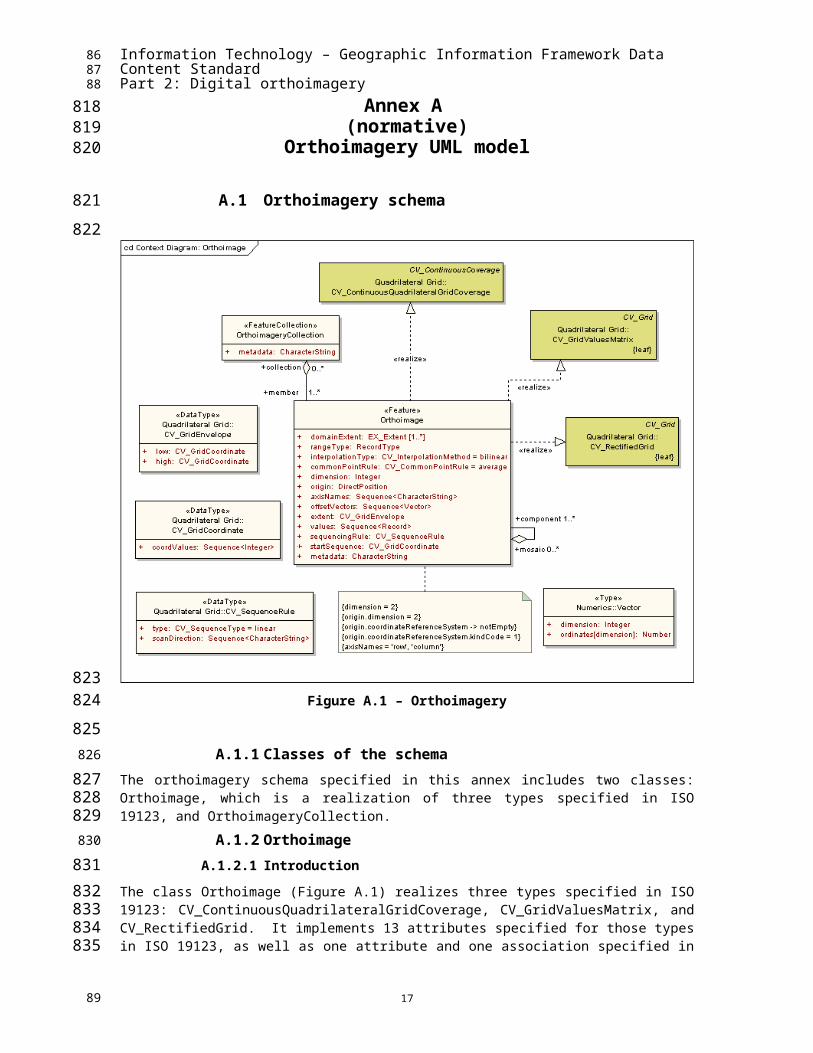
Figure A.1 – Orthoimagery
A.1.1 Classes of the schemaThe orthoimagery schema specified in this annex includes two classes: Orthoimage, which is a realization of three types specified in ISO 19123, and OrthoimageryCollection.
A.1.2 OrthoimageA.1.2.1 Introduction
The class Orthoimage (Figure A.1) realizes three types specified in ISO 19123: CV_ContinuousQuadrilateralGridCoverage, CV_GridValuesMatrix, and CV_RectifiedGrid. It implements 13 attributes specified for those types in ISO 19123, as well as one attribute and one association specified in this part. Its attributes use classes specified in ISO standards as data types.
13
5354
700701702
703
704
705706
707708
709710
711
712
713714715716717
55

Information Technology – Geographic Information Framework Data Content StandardPart 2: Digital orthoimagery
A.1.2.2 Attribute: domainExtentThe attribute domainExtent shall describe the extent of the domain of the orthoimagery coverage. It uses the data type EX_Extent specified in ISO 19115. EX_Extent has several subtypes including EX_GeographicBoundingBox, EX_BoundingPolygon, EX_GeographicDescription, EX_TemporalExtent, EX_SpatioTemporalExtent, and EX_VerticalExtent. This part requires that the attribute be populated with a value for at least one of these subtypes.
A.1.2.3 Attribute: rangeTypeThe attribute rangeType shall provide a description of the attributes in the range of the coverage. The class RecordType is specified in ISO 19103. An instance of RecordType consists of a set of keyword:value pairs in which the keyword is an attribute name and the value is the data type of the attribute.
A.1.2.4 Attribute: interpolationTypeThe attribute interpolationType shall identify the interpolation method recommended for evaluating the coverage. The code list CV_InterpolationMethod is specified in ISO 19123.
A.1.2.5 Attribute: commonPointRuleThe attribute commonPointRule shall identify a rule to be followed in evaluating a coverage if the position at which evaluation is to be done falls within or on the boundary between two or more domain objects. In the case of a grid coverage, it applies only if the position falls on a grid line. The code list CV-CommonPointRule is specified in ISO 19123.
A.1.2.6 Attribute: dimensionThe attribute dimension shall identify the dimension of the grid. In the case of orthoimagery, the grid dimension is always 2 as indicated by the constraint {dimension = 2}.
A.1.2.7 Attribute: originThe attribute origin shall identify the position of the origin of the grid coordinate system with respect to an external coordinate reference system. The data type DirectPosition (A.1.8) is specified in ISO 19107. The constraint {origin.dimension = 2} indicates that the DirectPosition shall be described by a 2D coordinateDirectPosition that has an optional association to the class SC_CRS (A.1.9) specified in ISO 19111. That association is mandatory for this part, as indicated by the constraint: {origin.coordinateReferenceSystem -> notEmpty}.
This part also specifies that the external coordinate reference system shall use either the North American Datum of 1983 (NAD83) or the datum defined for the World Geodetic System of 1984 (WGS84).
A.1.2.8 Attribute: axisNamesThe attribute axisNames shall provide a list of the names of the grid axes. The length of the list equals the value of the attribute dimension. This part requires the axis names to be “row” and “column” as indicated by the constraint {axisNames = “row”, “column”}.
A.1.2.9 Attribute: offsetVectorsThe attribute offsetVectors shall describe the orientation of the grid axes with respect to the external coordinate reference system as well as the spacing between grid lines. Its value is a Sequence of Vectors. The data type Vector (0) is specified in ISO/TS 19103. The length of the sequence shall equal the value of the attribute dimension. ISO 19123 specifies that the ordering of the sequence of offsetVectors shall be the same as the ordering of the sequence of axisNames.
A.1.2.10 Attribute: extentThe attribute extent shall identify the set of grid points for which attribute values are provided. The data type CV_GridEnvelope (A.1.4) is specified in ISO 19123.
14
5657
718
719720721722723
724
725726727728
729
730731
732
733734735736
737
738739
740
741742743744745746
747748749
750
751752753
754
755756757758759760
761
762763
58
Information Technology – Geographic Information Framework Data Content StandardPart 2: Digital orthoimagery
A.1.2.11 Attribute: valuesThe attribute values shall provide a sequence containing all of the values associated with grid points within the extent of the coverage. Each record in the sequence shall contain the list of values for a single grid point. The data type Record is specified in ISO 19103. For this attribute, each Record shall conform to the RecordType provided as the value for Orthoimage.rangeType.
A.1.2.12 Attribute: startSequenceThe attribute startSequence shall identify the grid coordinates of the point associated with the first record in the sequence of values. The data type CV_GridCoordinate (A.1.5) is specified in ISO 19123.
A.1.2.13 Attribute: sequencingRuleThe attribute sequencingRule shall identify the rule to be followed in assigning records from the sequence of values to individual grid points. The data type CV_SequenceRule (A.1.6) is specified in ISO 19123.
A.1.2.14 Attribute: metadataThe attribute metadata shall provide a link to metadata about the Orthoimage.
A.1.2.15 Association: AggregationThe optional association Aggregation may link an instance of Orthoimage to other instances in two ways. The role name collection identifies an OrthoimageryCollection to which the Orthoimage belongs. In the role of mosaic, an instance of Orthoimage is characterized as an aggregate of one or more other instances of Orthoimage. In the role of component, an instance of Orthoimage is characterized as a member of one or more mosaics.
A.1.3 OrthoimageryCollectionA.1.3.1 Introduction
The class OrthoimageryCollection represents a set of Orthoimages that are transferred as a set.
A.1.3.2 Attribute : metadataThe attribute metadata shall provide a link to metadata about the OrthoimageryCollection.
A.1.3.3 Associated role name: memberThe role name member identifies an Orthoimage that belongs to the OrthoimageryCollection.
A.1.4 CV_GridEnvelopeA.1.4.1 Introduction
The data type class CV_GridEnvelope has two attributes.
A.1.4.2 Attribute: lowThe attribute low takes as its value an instance of CV_GridCoordinate that contains the minimum coordinate of the grid envelope with respect to each axis of the grid.
A.1.4.3 Attribute: highThe attribute high takes as its value an instance of CV_GridCoordinate that contains the maximum coordinate of the grid envelope with respect to each axis of the grid.
A.1.5 CV_GridCoordinateA.1.5.1 Introduction
The data type class CV_GridCoordinate has a single attribute.
15
5960
764
765766767768
769
770771772
773
774775776
777
778
779
780781782783784
785
786
787
788
789
790
791
792
793
794
795
796797
798
799800
801
802
803
61

Information Technology – Geographic Information Framework Data Content StandardPart 2: Digital orthoimagery
A.1.5.2 Attribute: coordValuesThe attribute coordValues contains the coordinates of a grid point expressed as integer values.
A.1.6 CV_SequenceRuleA.1.6.1 Introduction
The data typeclass CV_SequenceRule describes the method to be followed in assigning records from the sequence of Orthoimage.values to grid points within the grid envelope. It has two attributes.
A.1.6.2 Attribute: typeThe attribute type identifies the sequencing method to be used. The data type CV_SequenceType is specified in ISO 19123. The default value is "linear". Other methods for sequential enumeration are described in Annex D of ISO 19123.
A.1.6.3 Attribute: scanDirectionThe attribute scanDirection is a sequence of signed axis names that indicates the direction in which sequencing operates. An additional element may be included in the sequence to describe interleaving of attribute values. In the case of linear scanning of a 2D grid, grid coordinates are incremented first along a grid line parallel to the first axis named in the list, and then along the second axis. To describe interleaving, the range of the coverage is treated similarly to a grid axis – the index of the list of values in a record is incremented in the same way that the grid coordinates are incremented.
EXAMPLE 1 In Figure A.2, the grid axes are named Row (R) and Column (C). The grid origin is at the upper left corner, and the axes are positive downward and to the right.
Figure A.2 – Examples of scan directions
EXAMPLE 2 Given grid axes named Row (R) and Column (C), and identifying the range of the grid coverage as A, the various forms of interleaving are identified by ordering the axes as shown in the table below.
16
Row
Column
Row
Column
Row Major(C, R) Order Column Major (R, C) Order
6263
804
805
806
807
808809810
811
812813814
815
816817818819820821822
823824
826
827
828829830
64
Information Technology – Geographic Information Framework Data Content StandardPart 2: Digital orthoimagery
Table A.1 – Examples of interleaving
Organization Axis Sequence
Band interleaved by pixel ACR or ARC
Band interleaved by row CAR
Band interleaved by column RAC
Band sequential CRA or RCA
A.1.7 VectorA.1.7.1 Introduction
The type class Vector is specified in ISO 19103. It has two attributes.
A.1.7.2 Attribute: dimensionThe attribute dimension indicates the dimension of the coordinate reference system, which is constrained to 2 in the case of this part.
A.1.7.3 Attribute: ordinatesThe attribute ordinates provides the ordinates relative to each axis of the coordinate reference system.
17
6566
831
832
833
834
835
836
837838
839
840841
67

Information Technology – Geographic Information Framework Data Content StandardPart 2: Digital orthoimagery
A.1.8 DirectPosition
Figure A.3 – DirectPosition
A.1.8.1 IntroductionThe data type class DirectPosition (Figure A.3) is specified in ISO 19107. DirectPosition has two attributes that carry the coordinates of a position and the coordinate dimension. It also has an optional association to the class SC_CRS specified in ISO 19111.
A.1.8.2 Attribute: coordinateThe attribute coordinate carries the coordinates of a single position as a sequence of numbers.
A.1.8.3 Attribute: dimensionThe attribute dimension identifies the dimension of the coordinate space. This information is derived through the association to SC_CRS. For framework orthoimagery, the value of dimension is constrained to 2.
{origin.dimension = 2}
18
6869
842
843
844845
846
847
848849850
851
852
853
854855856
857
70

Information Technology – Geographic Information Framework Data Content StandardPart 2: Digital orthoimagery
A.1.8.4 Association role: coordinateReferenceSystemThe association role coordinateReferenceSystem identifies the instance of SC_CRS to which the DirectPosition is referenced.
A.1.9 SC_CRSSC_CRS, as specified in ISO 19111 is an abstract class, meaning that it can only be instantiated as an instance of one of its concrete subclasses. This part requires that coordinate reference system be associated with either the North American Datum of 1983 (NAD83) or the datum defined for the World Geodetic System of 1984 (WGS84). These two coordinate reference systems are instances of the subclass SC_CoordinateReferenceSystem.
A.1.10 SC_CoordinateReferenceSystemA.1.10.1 Introduction
The data type class SC_CoordinateReferenceSystem inherits two attributes from SC_CRS and has four attributes defined for the class itself. Four of these attributes are optional; none of the four is required by this part, so they are not documented in the text below.
A.1.10.2 Attribute: kindCodeThe attribute kindCode is inherited from SC_CRS. Its data type is the enumeration SC_KindCode, which includes two values. The value for any 2D horizontal coordinate reference system is 1, generalCase.
A.1.10.3 Attribute: CRSIDThe attribute CRSID contains an identifier for the coordinate reference system. Its data type is RS_Identifier. RS_Identifier has one mandatory attribute, code; its value is of data type CharacterString.
19
7172
858
859860
861
862863864865866
867
868
869870871
872
873874875
876
877878879
880
73

Information Technology – Geographic Information Framework Data Content StandardPart 2: Digital orthoimagery
Table A.2 – Data dictionary for orthoimagery
Line Name/Role Name Definition Obligation/Condition
Maximum Occurrence Data Type Domain
1 OrthoimageSet of data forming an orthorectified image of a portion of the Earth's surface
<<Feature>> Lines 2-17
2 domainExtent Spatial extent of the image M * EX_Extent Unrestricted
3 rangeType Description of the types of values in the range of the coverage M 1 RecordType Unrestricted
4 interpolationTypeRecommended method for interpolating values at points within grid cells
M 1<<CodeList>>Coverage Core::CV_InterpolationMethod
Unrestricted. Default is bilinear
5 commonPointRuleRule to follow in interpolating a value at a point that falls on the boundary between two pixels
M 1<<CodeList>>Segmented Curve::CV_CommonPointRule
Unrestricted. Default is average
6 dimension Dimension of the image grid M 1 Integer 2
7 originCoordinates, in an external coordinate system, that map to grid coordinates 0, 0
M 1<<DataType>>Elevation::DirectPosition
Unrestricted
8 axisNames Names of the axes of the image grid M 1 Sequence<CharacterString> “row”, “column”
9 offsetVectors
Vectors that specify the orientation of the grid axes and the dimensions of the pixels in directions parallel to the axes
M 1 Sequence<Vector> Unrestricted
10 extent Limits of the set of pixels included in the image M 1
<<DataType>>Quadrilateral Grid:: CV_GridEnvelope
Unrestricted
11 sequencingRule Rule for assigning values to specific pixels M 1
<<DataType>>Quadrilateral Grid::CV_SequenceRule
Unrestricted
20
7475
881
76

Information Technology – Geographic Information Framework Data Content StandardPart 2: Digital orthoimagery
Line Name/Role Name Definition Obligation/Condition
Maximum Occurrence Data Type Domain
12 startSequence Grid point associated with the first record in the values sequence M 1
<<DataType>>Quadrilateral Grid::CV_GridCoordinate
Unrestricted
13 values Recorded radiance values M 1 Sequence<Record> Unrestricted
14 metadata Data about the Orthoimage M 1 CharacterString Free text
15 Role name: component Orthoimage that is part of a mosaic C/is image part of a mosaic? * <<Feature>>
Orthoimage Unrestricted
16 Role name: mosaic Orthoimage composed of smaller Orthoimages
C/is image composed of
parts?1 <<Feature>>
Orthoimage Unrestricted
17 Role name: collection Pointer to a set of orthoimages to which this orthoimage belongs O * <<FeatureCollection>>
OrthoimageryCollection Unrestricted
18 OrthoimageryCollection Orthoimages exchanged as a set <<FeatureCollection>> Lines 19-20
19 metadata Data about the OrthoimageryCollection M 1 CharacterString Free text
20 Role name: member Pointer to a Orthoimage included in the OrthoimageryCollection M * <<Feature>>
Orthoimage Unrestricted
21 CV_GridEnvelopeGrid coordinates for the diametrically opposed corners of the image
<<DataType>>Quadrilateral Grid Lines 22-23
22 low Minimal grid coordinate values of the image M 1
<<DataType>>Quadrilateral Grid::CV_GridCoordinate
Unrestricted
23 high Maximal grid coordinate values of the image M 1
<<DataType>>Quadrilateral Grid::CV_GridCoordinate
Unrestricted
24 CV_GridCoordinate Data type for holding the coordinates of a grid point
<<DataType>>Quadrilateral Grid Line 25
21
7778
79

Information Technology – Geographic Information Framework Data Content StandardPart 2: Digital orthoimagery
Line Name/Role Name Definition Obligation/Condition
Maximum Occurrence Data Type Domain
25 coordValuesNumber of pixel offsets from the origin of the grid parallel to each axis
M 1 Sequence<Integer> Positive
26 CV_SequenceRuleDescription of how grid points are ordered for association to the elements of the sequence values
<<DataType>>Qaudrilateral Grid Lines 27-28
27 type Identifier of the type of sequencing method M 1
<<CodeList>>Quadrilateral Grid::CV_SequenceType
Unrestricted
28 scanDirection
List of signed axisNames that indicates the order in which grid points shall be mapped to position within the sequence of values
M 1 Sequence<CharacterString> Unrestricted
29 Vector Quantity having magnitude and direction
<<Type>>Numerics Lines 30-31
30 dimensionDimension of the coordinate reference system in which the vector is specified
M 1 Integer 2
31 ordinates
Coordinates that describe the position of one end of a vector when the other end is taken to be at the origin of the coordinate reference system
M 2 Number Unrestricted
32 DirectPosition Description of a position relative to a coordinate reference system
<<DataType>>Elevation Lines 33-35
33 coordinate Numerical description of the spatial position M 1 Sequence<Number> Unrestricted
34 dimension Dimension of the coordinate space M 1 Integer 2
35 Role name: coordinateReferenceSystem
Spatial reference system to which the positions is associated
M 1 <<Abstract>>Spatial Referencing by Coordinates::
Unrestricted
22
8081
82

Information Technology – Geographic Information Framework Data Content StandardPart 2: Digital orthoimagery
Line Name/Role Name Definition Obligation/Condition
Maximum Occurrence Data Type Domain
SC_CRS
36 SC_CRS<<Abstract>>Spatial Referencing by Coordinates
Lines 37-38
37 kindCode Identifies the type of coordinate reference system M 1 <<enumeration>>
SC_KindCode
Restricted to the values in the enumeration SC_KindCode
38 remarks O 1 CharacterString Unrestricted
39 SC_CoordinateReferenceSystem Data describing a coordinate reference system
<<DataType>>Spatial Referencing by Coordinates
Lines 40-43
40 CRSID Name of the coordinate reference system M 1
<<DataType>>Reference system information::RS_Identifier
Unrestricted
41 alias Alternative name of the coordinate reference system O * CharacterString
42 validArea Area for which the coordinate reference system is valid O 1 EX_Extent
43 scope Application for which the coordinate reference system is valid O * CharacterString
44 MD_Identifier<<DataType>>Reference system information
Lines 45-46
45 authority O 1 CI_Citation
46 code Code that identifies the coordinate reference system M 1 CharacterString Unrestricted
47 RS_Identifier Information identifying a reference <<DataType>> Lines 48-49
23
8384
85

Information Technology – Geographic Information Framework Data Content StandardPart 2: Digital orthoimagery
Line Name/Role Name Definition Obligation/Condition
Maximum Occurrence Data Type Domain
reference system Reference system information
48 codeSpace O 1 CharacterString
49 version O 1 CharacterString
24
8687
88

Information Technology – Geographic Information Framework Data Content StandardPart 2: Digital orthoimagery
A.1.11 Code lists and enumerations
Figure A.4 – Code lists
A.1.11.1 CV_InterpolationMethod code listCV_InterpolationMethod is a CodeList of values for the attribute interpolationType.
Table A.3 – CodeList for CV_InterpolationMethod
Name Definition
nearestNeighbor
linear
quadratic
cubic
bilinear
biquadratic
bicubic
lostArea
barycentric
A.1.11.2 CV_SequenceType code listCV_SequenceType is a CodeList of values for the attribute type
Table A.4 –CodeList for CV_SequenceType
Name Definition
linear
25
8990
882
883
884885
886887
888
889
890
891892
893
894
895
91

Information Technology – Geographic Information Framework Data Content StandardPart 2: Digital orthoimagery
Name Definition
boustrophedonic
CantorDiagonal
spiral
Morton
Hilbert
A.1.11.3 CV_CommonPointRule code listCV_CommonPointRule is a CodeList of values for the attribute commonPointRule.
Table A.5 – CodeList for CV_CommonPointRule
Name Definition
average
low
high
all
start
end
A.1.11.4 SC_KindCode enumerationSC_KindCode is an enumeration of values for the attribute kindCode.
Table A.6 – SC_KindCode enumeration
Name Definition
generalCase
compound
26
9293
896897
898
899
900
901902
903
904
905
906907
94

Information Technology – Geographic Information Framework Data Content StandardPart 2: Digital orthoimagery
Annex B (informative)Data example
The data below represent an orthoimagery coverage that holds reflectances for three bands of the visible spectrum interleaved by pixel in row major sequence. The grid is referenced to NAD83 with a grid spacing of 1 arc second. The image covers an area 2 minutes in latitude by 5 minutes in longitude.
Table B.1 – Data example
Line Name/Role Name Value
1 Orthoimagery Coverage
2 domainExtent1
westBoundLongitude 76.00000
southBoundLatitude 39.46667
eastBoundLongitude 75.91667
northBoundLatitude 39.50000
3 rangeType
aName:attributeType
red:Integer
green:Integer
blue:Integer
4 interpolationType bilinear
5 interpolationParametersType ------
6 commonPointRule average
7 role name: data see row 8
8 Orthoimage
9 dimension 2
10 axisNames row, column
11 origin
coordinate 39.500, 76.000
dimension 2
coordinateReferenceSystem.kindCode 1
coordinateReferenceSystem.name NAD83
12 offsetVectors
dimension ordinates (1) ordinates (2)
2 -0.00028 0
2 0 -0.00028
13 extent low 0,0
27
9596
908909910
911912913914
915
916
97

Information Technology – Geographic Information Framework Data Content StandardPart 2: Digital orthoimagery
Line Name/Role Name Value
high 120,3000
14 startSequence 0,0
15 sequencingRuletype linear
scanDirection column, row
16 values
239, 17, 128
37, 219, 50
etc., for a sequence of 36421 records
17 role name: component -------
1 Uses Ex_GeographicBoundingBox, a subclass of EX_Extent.
28
9899
917
100

Information Technology – Geographic Information Framework Data Content StandardPart 2: Digital orthoimagery
Annex C (informative)
Additional information about control
Currently, there are three methods used to acquire the necessary control; from existing map or digital orthoimagery, from a ground survey, or from a platform specific navigation direct georeferencing system composed of an Airborne Global Positioning System (AGPS) and Inertial Navigation System (INS).
Control data in the form of survey ground control provides coordinates and elevations of known locations on the Earth’s surface which are used in the orthorectification process to obtain the precise location and orientation of the raw image at the time it was acquired. This is accomplished through a process called aerotriangulation which derives the camera attitude and positions by performing a space resection using ground control, tie points, and camera model geometry. When completed, this process provides the location and orientation information of the all the imagery allowing the user to locate any on-the-ground positions to known projections, coordinates, and accuracy standards.
Control derived from existing map or orthoimagery sources can also be used during the orthorectification process similarly to that of survey ground control. Control locations would consist of known horizontal and vertical values that, in turn, can be used in aerotriangulation process. For any given final orthoimage scale, control derived from a less accurate source is not recommended.
Direct georeferencing currently incorporates both airborne AGPS and INS data and is the measurement of sensor position and orientation allowing for direct relationship between locations on the imagery to locations on the ground, without the need for additional ground information over the project area.
Airborne GPS consists of a GPS unit on an aircraft that captures range measurements to satellites and uses triangulation techniques to compute the position of the receiver’s antenna and relates that position to the sensor.
Inertial Navigation System is composed of two components, one is the inertial measurement unit (IMU) comprised of a series of accelerometers and gyros that measure position, orientation, and velocity, and the second is the navigation processor of the INS which solves for the motion of the IMU. The two combined provide a navigation solution comprised of the platform’s position, velocity, and orientation.
When the data from the AGPS system is integrated with the INS data, the 3-dimensional and angular position of the aircraft sensor can be accurately estimated as the position of the AGPS complements that of the INS data providing location and orientation information helping to estimate and correct the errors of the imaging platform. The AGPS and INS data can then be used to help locate and orient the image in space during the orthorectification process.
At times, digital orthoimagery may be created using direct georeferencing information without the need of any ground survey control. In other cases, this information is used to augment the aerotriangulation block adjustment solution.
29
101102
918919920
921922923924
925926927928929930931932
933934935936937
938939940941
942943944
945946947948949
950951952953954
955956957
103

Information Technology – Geographic Information Framework Data Content StandardPart 2: Digital orthoimagery
Annex D (informative)Bibliography
The following documents contain provisions that are relevant to this part of the Framework Data Content Standard. Annex D of the Base Document (Part 0) lists informative references applicable to two or more of the parts of the standard. For dated references, only the edition cited applies. For undated references, the latest edition of the referenced document applies.
ANSI and ISO standards may be purchased through the ANSI eStandards Store at http://webstore.ansi.org/ansidocstore/default.asp, accessed November 2006.
American Society of Photogrammetry, 1980. Manual of photogrammetry, Fourth edition, Falls Church, VA, American Society of Photogrammetry
American Society for Photogrammetry and Remote Sensing (ASPRS), 1990, Specifications and Standards Committee, Accuracy standards for large-scale maps
ANSI NCITS 320-1998, Spatial data transfer standard (SDTS)
Applanix, http://www.applanix.com/products/posav_index.php#applications, accessed November 2006
Association of Geographic Information, 1996, AGI GIS dictionary, The University of Edinburgh and Association for Geographic Information, at http://www.geo.ed.ac.uk/agidict/welcome.html, accessed November 2006
Department of the Army, U.S. Corps of Engineers, 2002, EM 1110-1-1000 Engineering and design – Photogrammetric mapping
Falkner, E., Morgan, D., 2002. Aerial mapping – Methods and applications, 2nd edition, CRC Press, LLC
FGDC-STD-007.1-1998, Geospatial positioning accuracy standards, Part 1, Reporting methodology, http://www.fgdc.gov/standards/projects/FGDC-standards-projects/accuracy/part1/index_html/?searchterm=Geospatial%20positioning%20accuracy%20standards, accessed November 2006
FGDC-STD-008-1999, Content standards for digital orthoimagery, http://www.fgdc.gov/standards/projects/FGDC-standards-projects/orthoimagery/index_html/?searchterm=Content%20standards%20for%20digital%20orthoimagery, accessed November 2006
FGDC-STD-012-2002, Content standard for digital geospatial metadata: Extensions for remote sensing metadata, http://www.fgdc.gov/standards/projects/FGDC-standards-projects/csdgm_rs_ex/remote-sensing-metadata/?searchterm=Content%20standard%20for%20digital%20geospatial%20metadata, accessed November 2006
FGDC-STD-002.5, Spatial data transfer standard (SDTS), Part 5: Raster profile and extensions, http://www.fgdc.gov/standards/projects/FGDC-standards-projects/SDTS/sdts_pt5/srpe0299.pdf/view?searchterm=Spatial%20Data%20Transfer%20Standard, accessed November 2006
ISO/IEC 12087-1:1995, Information technology – Computer graphics and image processing – Image processing and interchange (IPI) – Functional specification – Part 1: Common architecture for imaging
Leica Geosystems GIS & Mapping, LLC, Photogrammetry – Photogrammetic terms, http://gis.leica-geosystems.com/Support/FocusOn/FocusOn_detail.aspx?article_ID=17, accessed November 2006
30
104105
958959960
961962963964
965966
967968
969970
971
972973
974975976
977978
979980
981982983984
985986987988
989990991992993
994995996
997998999
100010011002
106

Information Technology – Geographic Information Framework Data Content StandardPart 2: Digital orthoimagery
Maune, Dave, 2001, Digital elevation model technologies and applications: The DEM users manual, ASPRS
Pratt, William K., 1978, Digital image processing, John Wiley & Sons
Schowengerdt, Robert A.,1997, Remote sensing – Models and methods for image processing, 2nd edition, San Diego, CA, 522 pp.
U.S. Bureau of Budget, 1947, United States national map accuracy standards, http://rockyweb.cr.usgs.gov/nmpstds/nmas647.html, accessed November 2006
31
107108
10031004
1005
10061007
10081009
109


