PART 2 - CONSTRUCTION MATERIALS - Riverside, … 203-11.3 Composition and Grading. The Contractor...
23
12 PART 2 - CONSTRUCTION MATERIALS All as provided in Part 2 of the Standard Specifications for Public Works Construction, except as modified herein. Material lists may be modified from time to time by addendum insertions. 200.01 GENERAL All material shall comply with the Standard Specifications for Public Works Construction (Greenbook), latest adopted edition, with Amendments, except as modified herein. 200.02 MATERIAL AFFIDAVITS AND CERTIFICATIONS All pipe, fittings, valves and appurtenances shall be supplied with the manufacturer’s affidavit of compliance or certification of compliance stating that the furnished material has been sampled, tested and inspected in accordance with the reference requirements and that the results thereof comply with the requirements of the specifications. Certifications shall be wet signed originals and addressed to the City of Riverside and shall identify the item supplied, specify the project and plan number for which the material is being supplied. SECTION 200 – ROCK MATERIALS 200-2 UNTREATED BASE MATERIALS 200-2.1 General Crushed slag base is deleted as an option to crushed aggregate base. SECTION 201 - CONCRETE, MORTAR, AND RELATED MATERIALS 201-1 PORTLAND CEMENT CONCRETE 201-1.1.2 Concrete Used Concrete used for this project shall be in accordance with the Standards Specifications. Concrete for thrust blocks shall be Class 450-C-2000, Type II Cement. Concrete for curb, gutter, sidewalk, and driveway replacement shall be Class 520-C-2500, Type II Cement. 201-1.1.3 Concrete Specified by Compressive Strength Mix designs with more than 45% of fine and coarse aggregate shall not be permitted.
Transcript of PART 2 - CONSTRUCTION MATERIALS - Riverside, … 203-11.3 Composition and Grading. The Contractor...
12
PART 2 - CONSTRUCTION MATERIALS All as provided in Part 2 of the Standard Specifications for Public Works Construction, except as modified herein. Material lists may be modified from time to time by addendum insertions. 200.01 GENERAL All material shall comply with the Standard Specifications for Public Works Construction (Greenbook), latest adopted edition, with Amendments, except as modified herein. 200.02 MATERIAL AFFIDAVITS AND CERTIFICATIONS All pipe, fittings, valves and appurtenances shall be supplied with the manufacturer’s affidavit of compliance or certification of compliance stating that the furnished material has been sampled, tested and inspected in accordance with the reference requirements and that the results thereof comply with the requirements of the specifications. Certifications shall be wet signed originals and addressed to the City of Riverside and shall identify the item supplied, specify the project and plan number for which the material is being supplied.
SECTION 200 – ROCK MATERIALS 200-2 UNTREATED BASE MATERIALS 200-2.1 General Crushed slag base is deleted as an option to crushed aggregate base. SECTION 201 - CONCRETE, MORTAR, AND RELATED MATERIALS 201-1 PORTLAND CEMENT CONCRETE 201-1.1.2 Concrete Used Concrete used for this project shall be in accordance with the Standards Specifications. Concrete for thrust blocks shall be Class 450-C-2000, Type II Cement. Concrete for curb, gutter, sidewalk, and driveway replacement shall be Class 520-C-2500, Type II Cement. 201-1.1.3 Concrete Specified by Compressive Strength Mix designs with more than 45% of fine and coarse aggregate shall not be permitted.
13
201-1.2.1.1 Prepackaged Cement-aggregate Mix Prepackaged cement-aggregate mix shall not be allowed. 201-1.4 Mixing Hand mixed concrete shall not be allowed. 201-5 CEMENT MORTAR 201-5.1 General Hand mixed mortar shall not be allowed. Cement mortar shall be used within 45 minutes after mixing with water. SECTION 203 - BITUMINOUS MATERIALS 203-6 ASPHALT CONCRETE
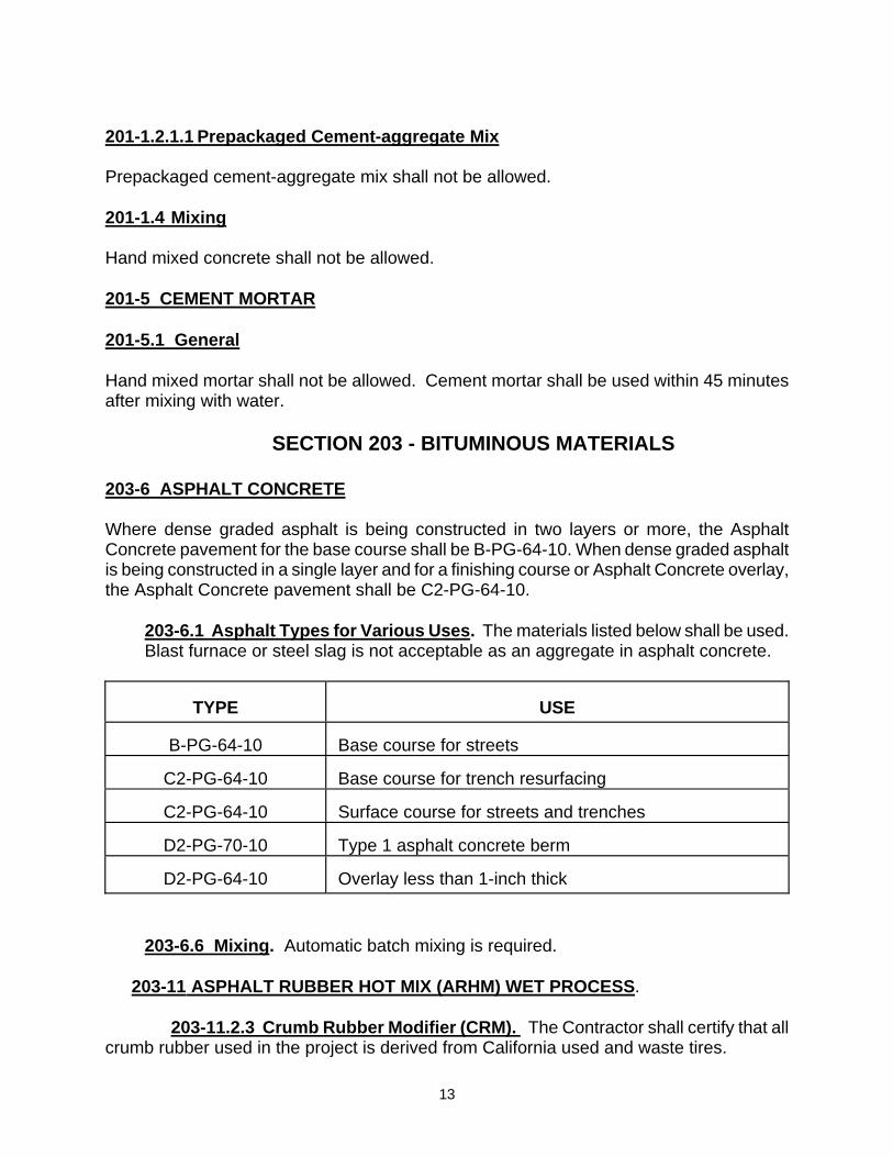
Where dense graded asphalt is being constructed in two layers or more, the Asphalt Concrete pavement for the base course shall be B-PG-64-10. When dense graded asphalt is being constructed in a single layer and for a finishing course or Asphalt Concrete overlay, the Asphalt Concrete pavement shall be C2-PG-64-10.
203-6.1 Asphalt Types for Various Uses. The materials listed below shall be used. Blast furnace or steel slag is not acceptable as an aggregate in asphalt concrete.
TYPE
USE
B-PG-64-10
Base course for streets
C2-PG-64-10
Base course for trench resurfacing
C2-PG-64-10
Surface course for streets and trenches
D2-PG-70-10
Type 1 asphalt concrete berm
D2-PG-64-10
Overlay less than 1-inch thick
203-6.6 Mixing. Automatic batch mixing is required.
203-11 ASPHALT RUBBER HOT MIX (ARHM) WET PROCESS.
203-11.2.3 Crumb Rubber Modifier (CRM). The Contractor shall certify that all crumb rubber used in the project is derived from California used and waste tires.

14
203-11.3 Composition and Grading. The Contractor shall use ARHM-GG-C with type I binder. SECTION 207 - PIPE The following Sections shall be used in the construction of the water main and appurtenances. All affidavits of compliance and certifications referenced herein shall be addressed to the City of Riverside, identifying the item supplied, and specifying the project or plan number for which the material is being supplied. Wet signed originals are required.
Written Certification from the pipe manufacturer indicating that all supplied pipe materials have been manufactured, sampled, and tested according to these Specifications, must be submitted by the Contractor and approved by the Engineer prior to construction. The manufacturer shall also supply copies of the certified physical test results, identifiable to the class and size of pipe, shift period, the date of test, and the purchase order number. Pipe furnished for this Contract shall be in accordance with the Standard Specifications unless otherwise specified herein.
The pipe manufacturer shall submit shop drawings covering all pipe manufacturing specifications and fabrication details, along with a layout sheet showing the physical placement of each piece of pipe for City approval before starting the manufacturing of pipe. The layout sheet shall include the invert elevation at the end of section of pipe (only required when the construction drawings include a pipeline profile). The pipe manufacturer shall provide pipe specials and fitting drawings showing all pertinent details and dimensions of elbows, reducers, connections, outlets, tees, crosses, bulkheads, closures and their required items. The Engineer / the inspector or his designee shall reserve the right to reject pipe on his own discretion. 207-9 DUCTILE IRON PIPE AND FITTINGS 207-9.1 General. This section applies only to ductile iron pipe (D.I.P.) and fittings for water distribution mains. All ductile iron pipe shall be Class 350 D.I.P., per A.N.S.I. A21.51/A.W.W.A. C-151. Fittings and appurtenances shall have a minimum pressure rating of 250 psi and shall be manufactured in accordance with A.N.S.I. A21.10/A.W.W.A. C-110 and/or A.N.S.I. A21.11/A.W.W.A. C-111. Ductile iron compact fittings shall have a minimum pressure rating of 350 psi and shall be manufactured in accordance with A.N.S.I. A21.53/A.W.W.A. C-153. Ductile Iron Pipe installed shall be pressure class 350.

15
Inspection within the manufacturing plant shall be provided by the manufacturer. Copies of all test reports shall be submitted to the Water Division. All Ductile Iron Pipe used for below ground installations shall be push on or mechanical joint type and encased in a polyethylene sleeve and cement lined as specified herein, unless otherwise indicated on the Plans or in these Specifications. Fittings and appurtenances shall consist of, but not be limited to, bends, tees, crosses,etc. 207-9.2.1.1 Certification by Manufacturer The manufacturer shall submit a wet signed original sworn statement that the pipe furnished has been sampled, tested and inspected in accordance with these Specifications and that the results thereof comply with the requirements of this Specification. 207-9.2.2 Pipe Joints Ductile Iron Pipe and fittings shall have one of the following joint types as shown on the Plans or Standard Drawings. Unless otherwise specified, all DIP shall have restrained joints.
(1) Mechanical joint ANSI A21.11/AWWA C111 (2) Flanged joint - ANSI A21.10/AWWA C110 (3) Restrained joint - ANSI A21.10/AWWA C110. "Field-LOK" Gaskets, for use
with “Tyton” joint pipe only, as manufactured by U.S. Pipe and Foundry Company, or “Fast-Grip” Gaskets, for use with “Fastite” joint pipe only, as manufactured by American Cast Iron Pipe Company, or "Grip Ring", as manufactured by Romac Industries, Inc., or “Lok-Ring” as manufactured by American Cast Iron Pipe Company, are accepted for joint restraint. EBBA Iron Megalugs are acceptable on 14-inch water mains and larger, Gripper Gaskets by the Gripper Gasket Company are not permitted. Any restrained joint gasket must be inspected, by the City Inspector, before use.
207-9.2.3 Fittings. This section covers all fittings required for closures, bends, tees, crosses, reducers, plugs, caps, blowoffs, fire hydrant buries, and connections to mainline valves shown on the Plans. All fittings shall be restrained mechanical joint. All fittings shall have a minimum pressure rating of 250 psi and shall be manufactured per ANSI A21.10/AWWA C110 and/or ANSI A21.11/AWWA C111. Ductile Iron compact fittings shall have a minimum pressure rating of 350 psi and shall be manufactured per ANSI A21.53/AWWA C153. 207-9.2.4 Lining and Coating. Ductile Iron Pipe and fittings shall be lined with cement mortar per ANSI A21.4/AWWA C104. The coating shall be a bituminous coating with a minimum thickness of one (1) mil.
16
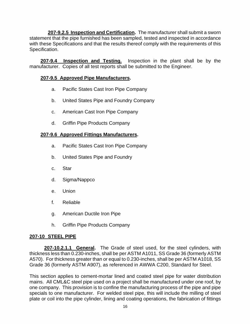
207-9.2.5 Inspection and Certification. The manufacturer shall submit a sworn statement that the pipe furnished has been sampled, tested and inspected in accordance with these Specifications and that the results thereof comply with the requirements of this Specification. 207-9.4 Inspection and Testing. Inspection in the plant shall be by the manufacturer. Copies of all test reports shall be submitted to the Engineer. 207-9.5 Approved Pipe Manufacturers.
a. Pacific States Cast Iron Pipe Company b. United States Pipe and Foundry Company c. American Cast Iron Pipe Company
d. Griffin Pipe Products Company 207-9.6 Approved Fittings Manufacturers.
a. Pacific States Cast Iron Pipe Company
b. United States Pipe and Foundry c. Star
d. Sigma/Nappco e. Union f. Reliable
g. American Ductile Iron Pipe
h. Griffin Pipe Products Company 207-10 STEEL PIPE 207-10.2.1.1 General. The Grade of steel used, for the steel cylinders, with thickness less than 0.230-inches, shall be per ASTM A1011, SS Grade 36 (formerly ASTM A570). For thickness greater than or equal to 0.230-inches, shall be per ASTM A1018, SS Grade 36 (formerly ASTM A907), as referenced in AWWA C200, Standard for Steel. This section applies to cement-mortar lined and coated steel pipe for water distribution mains. All CML&C steel pipe used on a project shall be manufactured under one roof, by one company. This provision is to confine the manufacturing process of the pipe and pipe specials to one manufacturer. For welded steel pipe, this will include the milling of steel plate or coil into the pipe cylinder, lining and coating operations, the fabrication of fittings
17
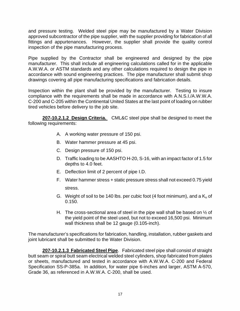
and pressure testing. Welded steel pipe may be manufactured by a Water Division approved subcontractor of the pipe supplier, with the supplier providing for fabrication of all fittings and appurtenances. However, the supplier shall provide the quality control inspection of the pipe manufacturing process. Pipe supplied by the Contractor shall be engineered and designed by the pipe manufacturer. This shall include all engineering calculations called for in the applicable A.W.W.A. or ASTM standards and any other calculations required to design the pipe in accordance with sound engineering practices. The pipe manufacturer shall submit shop drawings covering all pipe manufacturing specifications and fabrication details. Inspection within the plant shall be provided by the manufacturer. Testing to insure compliance with the requirements shall be made in accordance with A.N.S.I./A.W.W.A. C-200 and C-205 within the Continental United States at the last point of loading on rubber tired vehicles before delivery to the job site. 207-10.2.1.2 Design Criteria. CML&C steel pipe shall be designed to meet the following requirements:
A. A working water pressure of 150 psi.
B. Water hammer pressure at 45 psi.
C. Design pressure of 150 psi.
D. Traffic loading to be AASHTO H-20, S-16, with an impact factor of 1.5 for depths to 4.0 feet.
E. Deflection limit of 2 percent of pipe I.D.
F. Water hammer stress + static pressure stress shall not exceed 0.75 yield
stress.
G. Weight of soil to be 140 lbs. per cubic foot (4 foot minimum), and a Ku of 0.150.
H. The cross-sectional area of steel in the pipe wall shall be based on ½ of
the yield point of the steel used, but not to exceed 16,500 psi. Minimum wall thickness shall be 12 gauge (0.105-inch).
The manufacturer’s specifications for fabrication, handling, installation, rubber gaskets and joint lubricant shall be submitted to the Water Division. 207-10.2.1.3 Fabricated Steel Pipe. Fabricated steel pipe shall consist of straight butt seam or spiral butt seam electrical welded steel cylinders, shop fabricated from plates or sheets, manufactured and tested in accordance with A.W.W.A. C-200 and Federal Specification SS-P-385a. In addition, for water pipe 6-inches and larger, ASTM A-570, Grade 36, as referenced in A.W.W.A. C-200, shall be used.
18
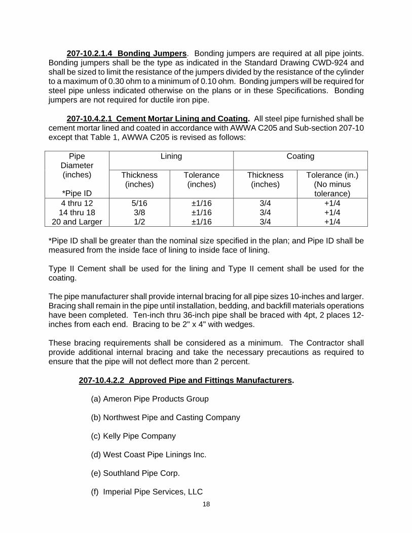
207-10.2.1.4 Bonding Jumpers. Bonding jumpers are required at all pipe joints. Bonding jumpers shall be the type as indicated in the Standard Drawing CWD-924 and shall be sized to limit the resistance of the jumpers divided by the resistance of the cylinder to a maximum of 0.30 ohm to a minimum of 0.10 ohm. Bonding jumpers will be required for steel pipe unless indicated otherwise on the plans or in these Specifications. Bonding jumpers are not required for ductile iron pipe. 207-10.4.2.1 Cement Mortar Lining and Coating. All steel pipe furnished shall be cement mortar lined and coated in accordance with AWWA C205 and Sub-section 207-10 except that Table 1, AWWA C205 is revised as follows:
Lining
Coating Pipe Diameter (inches)
*Pipe ID
Thickness (inches)
Tolerance (inches)
Thickness (inches)
Tolerance (in.) (No minus tolerance)
4 thru 12 14 thru 18
20 and Larger
5/16 3/8 1/2
±1/16 ±1/16 ±1/16
3/4 3/4 3/4
+1/4 +1/4 +1/4
*Pipe ID shall be greater than the nominal size specified in the plan; and Pipe ID shall be measured from the inside face of lining to inside face of lining. Type II Cement shall be used for the lining and Type II cement shall be used for the coating. The pipe manufacturer shall provide internal bracing for all pipe sizes 10-inches and larger. Bracing shall remain in the pipe until installation, bedding, and backfill materials operations have been completed. Ten-inch thru 36-inch pipe shall be braced with 4pt, 2 places 12-inches from each end. Bracing to be 2" x 4" with wedges. These bracing requirements shall be considered as a minimum. The Contractor shall provide additional internal bracing and take the necessary precautions as required to ensure that the pipe will not deflect more than 2 percent. 207-10.4.2.2 Approved Pipe and Fittings Manufacturers.
(a) Ameron Pipe Products Group (b) Northwest Pipe and Casting Company (c) Kelly Pipe Company (d) West Coast Pipe Linings Inc. (e) Southland Pipe Corp. (f) Imperial Pipe Services, LLC

19
207-25 MISCELLANEOUS PIPE 207-25.1 General These Specifications apply to miscellaneous piping used for appurtenant construction and water services. All miscellaneous piping shall conform to these Specifications unless shown otherwise on the Plans or Standard Drawings. 207-25.1.1 Copper Tubing or Pipe Copper tubing or pipe used for service connections, air valves or blow-offs shall be Type "K" soft copper conforming to ASTM B-88. Hard drawn copper shall be used for air valve and blow-off risers. When wrought copper solder type fittings are shown on the Plans or Standard Drawings the joints shall be soldered using a lead free, tin based alloy solder meeting Federal requirements for lead free solders mandated by the Federal Safe Drinking Water Act, with a flux specifically designed for the solder alloy. Use J. W. Harris Co., Stay Safe 50, Stay Safe Bridget, or City approved equal. 1” Copper- no sweat fittings are permitted. 2” Copper – full 20 feet sticks are to be used keeping solder couplings with provision to keep them to a minimum. 207-25.2 Red Brass Pipe Red brass pipe used for service connections, air valves or blow-offs shall conform to ASTM B-43. 207-25.3 Steel Pipe Steel pipe used in 4 inch and larger fire or domestic services and guard posts shall conform to ASTM A-120, Schedule 40. 207-25.4 Brass Pipe Brass to be used as 2-inch service bypasses shall conform to appropriate ASTM specification. 207-25.5 Gate Box Material The respective minimum thicknesses of steel pipe used for 8-inch and 10-inch gate boxes shall be 14 and 12 ga. Pipe shall be seamless steel, conforming with the requirements of ANSI/AWWA C-200. Material shall be factory dipped in Trumble Asphalt Dip, or an approved equal.

20
SECTION 210 - PAINT AND PROTECTIVE COATINGS 210-1.5 Paint Systems 210-1.6 PAINT AND PROTECTIVE COATINGS 4.06.1 Painting Schedule. All paint and protective coatings shall be holiday free. The following paint schedule shall apply to Water Division facilities:
a. Gate Box Caps & Rims - 1 coat Rust-Oleum #1069 Primer and
2 coats of no marking paint, traffic blue, # 6703, or City approved equal.
b. Air Valves - 1 coat Rust-Oleum #1069 Primer and 2 coats of Rust-Oleum #7638, Forest Green, Fuller O'Brien #312-81, Shutter Green, or Pervo #2428, Industrial Green.
c. Fire Hydrants - 1 coat Rust-Oleum #1069 Primer and 2 coats of either Fire Hydrant Pervo #2420, Rust- Oleum #7644 Federal Safety Yellow or Fuller O'Brien #312-74 Hi-Way Yellow. d. Guard Posts: 1 coat of Rust-Oleum #1069, Primer
and 2 coats of: Fuller O’Brien #312-81, Shutter Green, or
Rust-Oleum #7638, Forest Green, or Pervo #2428, Industrial Green
e. Vault Covers: 1 coat of Rust-Oleum #1069, Primer and 2 coats of:
Rust-Oleum #473, Industrial Aluminum, or Pervo #2404, Aluminum
f. Above Grade Piping: 1 coat of Dunn Edwards #43-5, Alkyd Primer and 2 coats of:
Dunn Edwards, Syn-Lustro 10 Series, San Tan
g. Fire Hydrants: 1 coat of Rust-Oleum #1069, Primer and 2 coats of:
Fuller O’Brien #312-74, Hi-Way Yellow, or Rust-Oleum #7644, Federal Safety Yellow, or Pervo #2420, Fire Hydrant Yellow
h. Blowoff Hydrants - 1 coat of Rust-Oleum #1060 Primer and 2 coats Rustoleum #7644, Federal Safety Yellow, Pervo #2420, or Fuller O'Brien #312-
74, Hi-Way Yellow. (Top of Hydrant) Fuller

21
O'Brien #312-80, National Blue Paint. i. Valves and Piping - Koppers #50, or City approved equal. j. Curb Marking - Traffic Blue #6703, Vista Paint or City approved equal. k. Miscellaneous Appurtenances - “Tnemec” Pota-Pox Plus series 140F epoxy coating, or City approved equal. l. All paint and protective coatings shall be holiday free. m. Suppliers
(1) Pervo Paint, Los Angeles - (213) 758-1147 (2) Fuller O'Brien, Fullerton - (714) 992-0720 (3) Vista Paint, Riverside - (951) 689-2501 (4) Decratrend, San Bernardino - (909) 888-3211
All the above paints, with the exception of red and black primer shall be industrial strength. A minimum thickness of 5 mils shall be attained after the final paint coat has dried. SECTION 250 - VALVING, APPURTENANCES AND MISCELLANEOUS MATERIALS 250-1 NUTS AND BOLTS. Where nuts and bolts are to be furnished for fastening flanged joints, they shall be hexagonal head machine bolts and hexagonal nuts. Steel Standard ASTM A-307 Grade B; dimensions of bolts and nuts, ANSI B-18.2.1; threads of bolts and nuts, ANSI B1.1 coarse thread series, Class 2A fit on bolts and Class 2B fit on the nuts; nuts and bolts shall be cadmium plated conforming to ASTM A-165, type TS; electroplated zinc per ASTM B-633, SC 1; or hot-dip galvanized per ASTM A-153, Class C. Minimum bolt lengths shall be three or four threads showing after completely tightened. Break-off bolts shall have a hole drilled in the shank with the dimensions of 11/32-inch (for 5/8-inch bolts) and 13/32-inch (for 3/4-inch bolts) and 2 3/8-inch deep and shall be supplied filled with silicone. 250-1.1 Check Valves. Check valves 2 ½-inch and larger shall conform to the following:
1. Valves shall be of a swing type with grooved ends complying with A.W.W.A. C-508. Valve bodies for valves up to 4-inches shall be bronze. Valves bodies for valves 6-inches to 12-inches shall be ductile iron.
2. Valves shall be designed for a working pressure of 175 psi.

22
3. The valves shall be supplied with an external lever arm, external spring, and a no-flow micro switch.
4. Check valves shall be operable in both the vertical and horizontal positions. 5. The disc arm, pin, and spring material shall be constructed of stainless steel
in conformance with ASTM A276, Type 316. The valve seat shall be bronze. Check valves made by Victaulic, Series 317 C-040 (060) have been approved by the Water Division. 250-2 GASKETS. Where gaskets are to be furnished, they shall be 1/8" minimum thickness, micro finish, full face, red rubber style 150 by “Active Packing” or City approved equal. 250-3 INSULATION GASKETS. Unless otherwise specified, insulation gaskets shall conform to the following:
1. The insulation gasket shall fit between the class of flanges as specified, with a pressure rating equal to or greater than the flange pressure rating.
2. Insulation gaskets shall be full pattern, fabric-reinforced phenolic, neoprene
face, 1/8-inch thick.
3. The gaskets shall have the following assembly minimum physical characteristics:
a. Compression strength..........................................................24,000 psi
b. Dielectric strength ................................................................. 500 V/Mil
c. Operating temperature......................................................up to 175° F
d. Water absorption ......................................................................... 1.6%
4. A one-piece Acetal Resin sleeve and Washer shall be used in combination
with a single phenolic washer on each bolt. A steel washer designed to be used with the insulating washer shall be used, one each side of the flange bolts.
a. One-piece sleeve washer shall have the following physical
characteristics:
(1) Sleeve thickness ..........................................................1/32-inch (2) Washer thickness .........................................................5/32-inch

23
(3) Dielectric strength...................................................... 1200 V/Mil (4) Operating temperature ............................................up to 175° F (5) Water absorption ..................................................... 0.22% Max.
b. Single phenolic washers shall have the following physical
characteristics:
(1) Thickness .......................................................................1/8-inch (2) Dielectric strength........................................................ 500 V/Mil (3) Compressive strength.................................................26,000 psi (4) Operating temperature ............................................up to 300° F (5) Water absorption .......................................................... 1% Max.
c. Flange Insulation kits shall be:
(1) PSI Products, Inc., Burbank, California
(2) Central Plastics Company, Shawnie, Oklahoma (3) CALPICO Inc., San Francisco, California
250-4 BUTTERFLY VALVES. Butterfly valves shall conform to the latest revision of AWWA C504 and the following:
1. Butterfly valves and operators shall be class 150B, constructed for direct burial and
have flanged ends. 2. Butterfly valves shall be furnished with operators of the traveling nut or worm gear
type, self-locking in any position, and sealed (with gaskets), and lubricated to withstand a submersion in water to 10 psi. The valve shall open by counter-clockwise rotation of a 2-inch square AWWA operating nut.
3. The operator shall be capable of meeting the torque requirements for opening and
closing the valve against: a. 150 psi upstream and 0 psi downstream pressure. b. Maximum inlet-outlet velocity of 12 feet per second, normal velocity of 6 feet per
second, and shall be provided with AWWA stops capable of absorbing up to 300 foot-pounds of input torque without damage to the valve or operator.

24
4. Butterfly valves shall have Buna N seat bonded or mechanically retained without use
of metal retainers or other devices located in the flow stream, to the body and have a disc seating edge of ni-chrome or stainless steel. All internal mountings or working parts shall be stainless steel. All internal nuts and bolts, excepting the operating nut shall be of stainless steel.
Butterfly valves shall have the shaft V-type self-adjusting packing. The shaft shall not
be exposed between the valve body and the operator. 5. The use of a stop or lug cast integrally with or mechanically secured to the body for
the purpose of limiting disc travel by means of direct contact or interference with the valve disc in either the open or closed position and which utilizes a ferrous metal bearing surface in direct rubbing contact with an opposing ferrous metal surface, will not be acceptable.
6. Butterfly valves shall be furnished with records of tests specified in AWWA C504,
Section 2.3 and Section 5. Butterfly valve seats shall be tested and certified for a 150 psi working pressure. The certificate shall be attached to the Butterfly valve. All valves shall be furnished with certified drawings and parts list of the value and operator. An affidavit of compliance to AWWA C504 shall be furnished for all valves. Five sets of the above information shall be furnished to the City.
7. Butterfly valves shall have their internal and external surfaces epoxy coated, except
flange faces and stainless steel and rubber surfaces, with a minimum of 8 mils of "Ameron” Amercoat 400 epoxy coating, Holiday Free, or City approved equal. "Ameron” Amercoat 400 epoxy coating shall be applied at the manufacturer's plant or approved manufacturer's representative's plant in accordance with the manufacturer's application specifications.
250-4.1.1 Approved Manufacturers:
a. Pratt - Groundhog, Triton XR-70.
b. Mueller – Lineseal III or City approved equal. c. Dezurik
250-5 GATE VALVES.
250-5.1 1/4-inch to 3-inch Gate Valves. Unless otherwise specified, bronze gate valves 1/4-inch through 3-inch shall conform to Specification MSS SP-80, and the following:
a. Gate valves shall be 300 psi WOG, 150 psi SWP non-rising stem, union bonnet, solid wedge disc and screw ends.
b. Gate valves used in 2-inch air valve, 2-inch blowoff or 2-inch service
installations shall have the handwheel replaced with a 1-inch square x 1/2-inch

25
cast iron operator nut. c. 2” Bronze gate valves shall be:
(1) Milwaukee Valve, Co. 1141
250-5.2 Resilient Seat Gate Valves. 250-5.2.1 General. This section of the Specification covers resilient-seated gate
valves for use in the water distribution system. Resilient-seated gate valves shall conform to the latest revision of AWWA C509 and the following:
(1) Resilient-seated gate valves shall be iron bodied with all bronze internal mountings and working parts. Valve stems shall contain no more than 5% zinc and 2% aluminum.
(2) Resilient-seated gate valves shall have non-rising stems, "O"-ring sealed
with two “O”-rings above the thrust collar, with a 2-inch square operating nut, opening counter-clockwise, and shall be designed for 200 psi water working pressure.
(3) Resilient-seated gate valves shall have sizes and type of valve ends as
shown on the plans or Standard Drawings. (4) Resilient-seated gate valve suppliers shall furnish the City with an affidavit of
compliance to AWWA C509. (5) Resilient-seated gate valves shall have their internal and external surface
epoxy coated, Holiday Free, except stainless steel and rubber surface with epoxy applied by the manufacturer of the valve.
250-5.2.2 Resilient Seat Gate Valves - Tapping. Tapping gate valves shall conform to all requirements of Subsection 250-5.2.1 and the following:
(1) Tapping valves shall have a Class 125, ANSI B16.1 flanged inlet and an outlet as shown on the construction plans.
(2) Tapping valves shall be compatible with the tapping sleeve and the tapping
machine utilized for wet tapping the water main. 250-5.2.3 Approved Manufacturers.
(1) American Flow Control Series 2500 (2) Clow Series 6100

26
(3) AVK Series 25 (4) Mueller Model A2360 (5) M & H Style 4067 NRS
250-5.3 Tapping Sleeves.
a. Tapping sleeves shall be:
(1) Ductile Iron body construction, with mechanical type joints on both sleeve ends, and a class 125 ANSI B16.1 flanged outlet.
(2) ASTM A-276, type 304 or 304L stainless steel body construction, with
full circumference gasket, and flange outlets meeting the requirements of Section 250-9. Flanges materials may include ASTM A-276, type 304 or 304L stainless steel.
b. Sleeves shall be compatible with the tapping gate valves. c. Sleeves shall be designed for a working pressure of 200 psi and be supplied
with a 1/2" or 3/4" IPF coupling or tap and corporation stop for pressure testing sleeve.
250-5.3.1 Approved Manufacturers.
Stainless Steel Sleeve
(1) Smith-Blair 662 and 663 (2) Romac SST or Romac FTS 420 (3) Powerseal 3490-AS
Mechanical Type Joint
(1) Mueller-Mechanical Joint Tapping Sleeve (2) Clow-Mechanical Joint Tapping Sleeve (3) American Flow Control - Mechanical Joint Tapping Sleeve
250-5.4 Abandoning Existing Valves. All existing valves shall be abandoned by Contractor unless otherwise noted on the plans. After pipelines have been tested and disinfected by Contractor, and accepted by City, and after City has completed all service connections and waterline connections, Contractor shall remove valve cans a minimum of 12" below finish grade, remove operating nut extensions, and fill valve cans with concrete. Thereafter, Contractor shall sawcut existing asphalt concrete pavement (2' square section)

27
or concrete (at construction joints) around existing valve boxes, remove said asphalt concrete pavement or concrete and dispose of same at a legal disposal site, and place concrete or asphalt concrete pavement over abandoned valve boxes. 250-6 VALVE BOX CAPS. Where valve box caps are to be furnished; the valve box caps shall be composed of 8-inch or 10-inch valve boxes and shall consist of a cap of cast iron with the cap marked CWD with the City of Riverside pattern. The cap shall be supplied with two coats of paint thereon and one coat primer. See painting schedule, Section 210-1.5. Cap shall be manufactured by South Bay Foundry, San Diego, CA, or City approved equal. 250-7 AIR VALVES.
Unless otherwise specified, air valves, 2-inch and larger, shall conform to the following:
1. Air valves shall have their internal body casting epoxy coated with a minimum of 12 mils of “Ameron” Amercoat 370 epoxy coating, Holiday Free, or City approved equal. The “Ameron” Amercoat 370 epoxy coating shall be applied at the manufacturer's plant or approved manufacturer's representative's plant, in accordance with the manufacturer's application specifications.
2. Air valves shall be:
Crispin, 2-inch - UL20.1-Air and Vacuum Valve
250-7.1 Abandoning Existing Air Valves. See Abandoning Existing Valves (Section 250-5.4).
a. All existing air valves shall be abandoned by Contractor unless otherwise noted
on the plans. After pipelines have been tested and disinfected by Contractor, and accepted by City, Contractor shall remove air valves and piping a minimum of 12" below finish grade and fill void and piping with concrete. Thereafter, Contractor shall saw cut existing concrete at construction joints around abandoned air valves, remove said concrete and dispose of same at a legal disposal site, and place concrete over abandoned air valve. If existing air valves are located in an area without concrete, Contractor shall remove and replace, in kind, the area around abandoned air valves.
b. Contractor shall restore landscaping and existing improvements around
abandoned fire hydrants.
c. Air Valves shall be delivered to the City of Riverside, Utilities Operation Center. Call the Water Superintendent at (951) 351-6384.
28
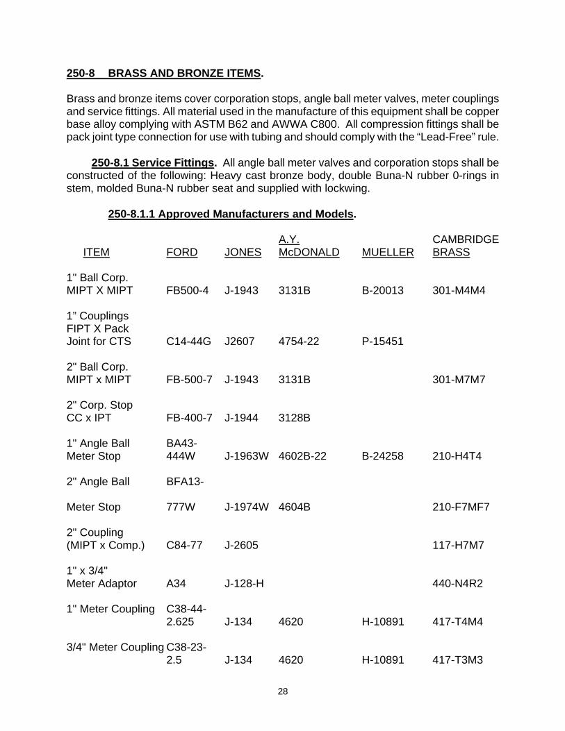
250-8 BRASS AND BRONZE ITEMS. Brass and bronze items cover corporation stops, angle ball meter valves, meter couplings and service fittings. All material used in the manufacture of this equipment shall be copper base alloy complying with ASTM B62 and AWWA C800. All compression fittings shall be pack joint type connection for use with tubing and should comply with the “Lead-Free” rule. 250-8.1 Service Fittings. All angle ball meter valves and corporation stops shall be constructed of the following: Heavy cast bronze body, double Buna-N rubber 0-rings in stem, molded Buna-N rubber seat and supplied with lockwing. 250-8.1.1 Approved Manufacturers and Models. A.Y. CAMBRIDGE ITEM FORD JONES McDONALD MUELLER BRASS 1" Ball Corp. MIPT X MIPT FB500-4 J-1943 3131B B-20013 301-M4M4 1” Couplings FIPT X Pack Joint for CTS C14-44G J2607 4754-22 P-15451 2" Ball Corp. MIPT x MIPT FB-500-7 J-1943 3131B 301-M7M7 2" Corp. Stop CC x IPT FB-400-7 J-1944 3128B 1" Angle Ball BA43- Meter Stop 444W J-1963W 4602B-22 B-24258 210-H4T4 2" Angle Ball BFA13- Meter Stop 777W J-1974W 4604B 210-F7MF7 2" Coupling (MIPT x Comp.) C84-77 J-2605 117-H7M7 1" x 3/4" Meter Adaptor A34 J-128-H 440-N4R2 1" Meter Coupling C38-44- 2.625 J-134 4620 H-10891 417-T4M4 3/4" Meter Coupling C38-23- 2.5 J-134 4620 H-10891 417-T3M3
29
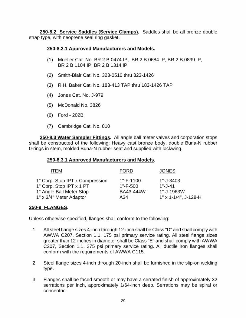
250-8.2 Service Saddles (Service Clamps). Saddles shall be all bronze double strap type, with neoprene seal ring gasket. 250-8.2.1 Approved Manufacturers and Models.
(1) Mueller Cat. No. BR 2 B 0474 IP, BR 2 B 0684 IP, BR 2 B 0899 IP, BR 2 B 1104 IP, BR 2 B 1314 IP
(2) Smith-Blair Cat. No. 323-0510 thru 323-1426
(3) R.H. Baker Cat. No. 183-413 TAP thru 183-1426 TAP
(4) Jones Cat. No. J-979
(5) McDonald No. 3826
(6) Ford - 202B
(7) Cambridge Cat. No. 810
250-8.3 Water Sampler Fittings. All angle ball meter valves and corporation stops shall be constructed of the following: Heavy cast bronze body, double Buna-N rubber 0-rings in stem, molded Buna-N rubber seat and supplied with lockwing. 250-8.3.1 Approved Manufacturers and Models.
ITEM FORD JONES 1" Corp. Stop IPT x Compression 1"-F-1100 1"-J-3403 1" Corp. Stop IPT x 1 PT 1"-F-500 1"-J-41 1" Angle Ball Meter Stop BA43-444W 1"-J-1963W 1" x 3/4" Meter Adaptor A34 1" x 1-1/4", J-128-H
250-9 FLANGES. Unless otherwise specified, flanges shall conform to the following:
1. All steel flange sizes 4-inch through 12-inch shall be Class "D" and shall comply with AWWA C207, Section 1.1, 175 psi primary service rating. All steel flange sizes greater than 12-inches in diameter shall be Class "E" and shall comply with AWWA C207, Section 1.1, 275 psi primary service rating. All ductile iron flanges shall conform with the requirements of AWWA C115.
2. Steel flange sizes 4-inch through 20-inch shall be furnished in the slip-on welding
type. 3. Flanges shall be faced smooth or may have a serrated finish of approximately 32
serrations per inch, approximately 1/64-inch deep. Serrations may be spiral or concentric.

30
4. Plate or blind flanges shall have all flange faces machined flat and shall be center
drilled and tapped, 1-inch IPT, 4-inch through 10-inch; 2-inch IPT 12-inch and larger; and furnished with a standard square head pipe plug.
5. Final machining on the contact faces of all flanges shall be done prior to being
welded to the full length adjacent steel-plate section. Flange faces shall be checked with a straight edge and shall be perpendicular to the pipeline. All warped flanges will be returned to the pipe company for adjustment. The Contractor is responsible for all additional expenses and delays.
6. For 1-1/2 inch and 2-inch water service installations, a 2-inch brass screw meter
flange shall be used, conforming with Section 4.4 of AWWA C701. 250-10 FIRE HYDRANTS/BLOWOFF ASSEMBLIES. Unless otherwise specified, fire hydrants and blow off hydrants shall conform to the latest revision of AWWA C503 and the following:
1. Hydrants shall have 6- inch flanged inlet connection with 6-3/4 inch holes drilled on a 9-3/8 inch bolt circle.
2. Hydrants shall have outlet nozzles of the quantity and size specified with National
Standard Hose Thread. 3. Hydrants shall be furnished with 1-3/4 inch pentagon spanner nuts on operator
stems and nozzle caps. Nozzle caps shall be constructed of cast iron. 4. Hydrants from Clow Corporation shall be supplied with Type B carrier valves. Valve
rubber shall be 5/8-inch thick for 2-1/2 inch outlets and 3/4-inch thick for 4- inch outlets.
5. Hydrant valves shall be slow opening. 6. Hydrant stems shall have "O" ring packing and be constructed of ASTM B-62 (85%
copper, 5% tin, 5% lead, 5% zinc). 7. Hydrants shall be painted per AWWA C503. Exterior color shall be fire hydrant
yellow. 8. Hydrant supplier shall furnish an affidavit of compliance to AWWA C503. 9. Hydrant (1 - 2-1/2" and 1 - 4" Outlets), Super Hydrant (2 - 2-1/2" and 1 - 4" Outlets)

31
250-10.1 Approved Manufacturers and Models.
a. Regular Hydrant:
CLOW CORP., Corona, California, Ranger, 900 Series, Model 950 JAMES JONES COMPANY, El Monte, California, Model J-4040-C
AMERICAN AVK CO., Fresno, California, Model 24/70
b. Super Hydrant:
CLOW CORP., Corona, California, Ranger, 900 Series, Model 960 JAMES JONES COMPANY, El Monte, California, Model J-4060-C
AMERICAN AVK CO., Fresno, California, Model 24/90 250-10.2 Abandoning Existing Fire Hydrants.
a. All existing fire hydrants shall be abandoned by Contractor unless otherwise
noted on the plans. After pipelines have been tested and disinfected by Contractor, and accepted by City, Contractor shall remove fire hydrants and fire hydrant burys a minimum of 12" below finish grade and fill fire hydrant burys with concrete. Thereafter, Contractor shall sawcut existing concrete at construction joints around abandoned fire hydrant burys, remove said concrete and dispose of same at a legal disposal site, and place concrete over abandoned fire hydrant burys. If existing fire hydrants are located in an area without concrete, Contractor shall remove and replace in kind area around abandoned fire hydrant burys.
b. Contractor shall restore landscaping and existing improvements around
abandoned fire hydrants. c. Contractor shall notify City Fire Department of the location of the fire hydrants
that are out of service. d. Hydrants to be delivered to the City of Riverside, Utilities Operation Center.
Call the Water Maintenance Superintendent at (951) 351-6384. 250-10.3 Abandoning Existing Blowoffs. See Abandoning Existing Fire Hydrants (Section 250-10.2) and Abandoning Existing Valves (Section 250-5.4).
250-11 BOLTED, SLEEVE-TYPE COUPLINGS. Unless otherwise specified bolted, sleeve-type couplings shall conform to the latest
revision of AWWA C219.
32
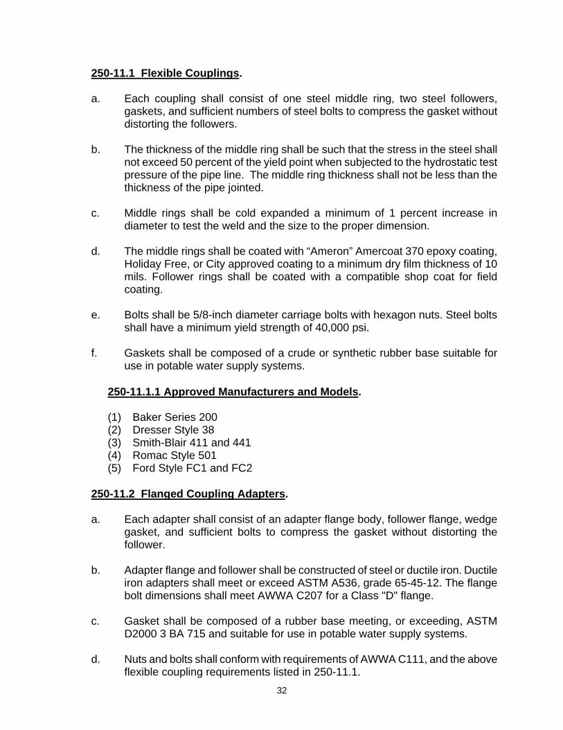
250-11.1 Flexible Couplings.
a. Each coupling shall consist of one steel middle ring, two steel followers, gaskets, and sufficient numbers of steel bolts to compress the gasket without distorting the followers.
b. The thickness of the middle ring shall be such that the stress in the steel shall
not exceed 50 percent of the yield point when subjected to the hydrostatic test pressure of the pipe line. The middle ring thickness shall not be less than the thickness of the pipe jointed.
c. Middle rings shall be cold expanded a minimum of 1 percent increase in
diameter to test the weld and the size to the proper dimension. d. The middle rings shall be coated with “Ameron” Amercoat 370 epoxy coating,
Holiday Free, or City approved coating to a minimum dry film thickness of 10 mils. Follower rings shall be coated with a compatible shop coat for field coating.
e. Bolts shall be 5/8-inch diameter carriage bolts with hexagon nuts. Steel bolts
shall have a minimum yield strength of 40,000 psi. f. Gaskets shall be composed of a crude or synthetic rubber base suitable for
use in potable water supply systems. 250-11.1.1 Approved Manufacturers and Models.
(1) Baker Series 200 (2) Dresser Style 38 (3) Smith-Blair 411 and 441 (4) Romac Style 501 (5) Ford Style FC1 and FC2
250-11.2 Flanged Coupling Adapters.
a. Each adapter shall consist of an adapter flange body, follower flange, wedge gasket, and sufficient bolts to compress the gasket without distorting the follower.
b. Adapter flange and follower shall be constructed of steel or ductile iron. Ductile
iron adapters shall meet or exceed ASTM A536, grade 65-45-12. The flange bolt dimensions shall meet AWWA C207 for a Class "D" flange.
c. Gasket shall be composed of a rubber base meeting, or exceeding, ASTM
D2000 3 BA 715 and suitable for use in potable water supply systems. d. Nuts and bolts shall conform with requirements of AWWA C111, and the above
flexible coupling requirements listed in 250-11.1.

33
e. Adapter flange and follower shall be painted with a factory applied shop coat.
250-11.2.1 Approved Manufacturers and Models.
(1) Baker Series 601 (2) Smith-Blair 912, 913, and 914 (3) Ford Style FFCA (4) Romac FCA 501
250-12 METER BOXES Pre-cast concrete meter boxes shall be provided for 5/8-inch through 2-inch water meters. Meter boxes shall be furnished with a Polymer concrete cover and lid except where cast iron or steel traffic covers are specified. Where meter boxes are to be placed within a landscaped area, plastic boxes shall be used.
250-12.1 Approved Manufacturers and Models. Meter boxes provided shall be one of the following models. Many other manufacturers are readily available. Any substitution must be approved by the Engineer and shall be of the same size and description as those specified below:
a. 3/4" and 1" Meters:
Manufacturer Model Armorcast No. 37 (Polymer Concrete Cover) Carson Industries 1017 (Plastic Box and Cover with Reading Lid)
b. 1-1/2" and 2" Meters:
Manufacturer Model Armorcast No. 65 (Polymer Concrete Cover)
250-12.2 Terminal Housing Boxes Meter boxes shall be provided for test lead terminal housing and water quality sampling station. The size shall be the same as for a 5/8-inch meter to 1-inch meter but shall be furnished with a cast iron traffic cover painted yellow.
250-12.3 Approved Manufacturers and Models. Terminal housing boxes provided shall be one of the following models. Many other manufacturers are readily available. Any substitution must be approved by the Engineer and shall be of the same size and description as those specified below:
Manufacturer Model Armorcast No. 37 (Polymer Concrete Cover)

34
250-13 JOINT LUBRICANT
Joint lubricant used on ductile iron and steel pipe joints where there is no internal sealing of the space between the pipe sections shall contain an effective preservative per U.S. Pharmacopeia, 1975, 19th Edition. The supplier shall submit test reports from an independent laboratory for approval.
250-14 POLYETHYLENE ENCASEMENT
Polyethylene encasement shall have a minimum thickness of 8 mil and conform with Section 4.1 of AWWA C105/ANSI A21.5. Double wrap and tape all fittings. Pipe should be wrapped and taped per Ductile Iron Pipe Research Association (DIPRA) recommended methods.