Part 2 and 3 - vutbr.cz
34
Foundations/footings Part 2 and 3 Simplified design of the dimensions in contact with soil Simplified design of the footings as a structure – struct. design.
Transcript of Part 2 and 3 - vutbr.cz

Foundations/footingsPart 2 and 3
Simplified design of the dimensions in contact with soil
Simplified design of the footings as a structure – struct. design.

Simplified model of compressive contact pressure distribution used for the design of footing padsVd is resulting vertical force
Vd= Nd + ZdZd Self-weight of the pad + backfill + relevant part of the floor slabNd Axial force from the superstructure (more loading cases possible)
Md Bending moment in the foot of actual column (more loading cases possible)
Hd Horizontal force in the foot of actual column (more loading cases possible)
Aef Effective contact areaed (e)= ( Md + Hd . H)/ (Nd + Zd)
Aef = (L‐2 ed) . B !correction!

Geotechnical design of a footing pad
Zd Self-weight of the pad + backfill + relevant part of the floor slab + blinding concrete (if used)Nd Axial force from the superstructure (more loading cases possible)Md Bending moment in the foot of actual column (more loading cases possible)Hd Horizontal force in the foot of actual column (more loading cases possible)B, L Plan dimensions of the padAef Effective contact areaed (e)= ( Md + Hd . H)/ (Nd + Zd)
Aef = (L‐2 ed) . B
Contact pressure z
z = (Nd + Zd) / ((L‐2 ed) . B)

Simplified design of the pad dimensions (Geo)Condition of reliability for ULS STR (pad sinking)zd≤ Rd has to checked.A) Design – proposal1. We know Md(i), Hd(i), Nd(i), Rd [index (i) means for more
loading cases].2. Zd and H must be estimated3. Usually: H = approx. (0,5‐1,0)m, Zd = approx.
(0,1 ‐0,2 ) of max Nd (depends on Rd)4. Plan shape must be estimated B=L or L = x. B, (x
= 1 to 0,6 not less).5. Max ed should be calculated (all forces can be
taken as (+) if Mdand Hd acts in the same manner.)
6. max ed (i)= max [( Md(i) + Hd(i) . H)/ (Nd (i) + Zd)] where ed is the eccentricity in direction of L.
7. We lay z Rd witch is known from geo data and we can write: Rd = (Nd + Zd) / ((L‐2 ed) . L)
8. From this equation we can easy calculate L and in next step B as minimum plan dimensions.
9. Calculation of height H, in fact to choose plain (PC) orreinforced concrete (RC).
10. Decision about blinding concrete (about 50‐80 mm of plain concrete of lower strength class). By RC pads, only.

B. Design – reviewreview for ULS ‐ STR1. Calculation of the correct self‐weight of revived pad and
weight of the backfill , flooring. (Together = Zd)2. Calculation of deciding loading variants (from the
superstructure)‐ max value of Nd(i) + corresponding Md(i) and Hd(i)
‐ min value of Nd(i) + corresponding Md(i) and Hd(i)
‐ max value of Md(i) + corresponding Hd(i) and Nd(i)
‐ min value of Md(i) + corresponding Hd(i) and Nd(i)
‐ max value of Hd(i) + corresponding Md(i) and Nd(i)
‐ min value of Hd(i) + corresponding Md(i) and Nd(i)
By the review we respect all signs of used quantities!As safe simplification comb. max INd(i) l + ext Hd(i) + ext Md(i) can be used.
3. we find ed(i)= ( Md(i) + Hd(i) . H)/ (Nd(i) + Zd) = ed4. we calculate z(i) =(Nd(i) + Zd)/(B. (L‐2ed(i)))
zd (i) ≤Rd should be fulfilled for all extreme combination of M, N and H.
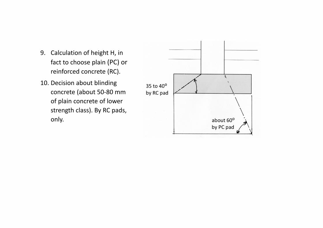
Stability of a padA pad should not overturn and move horizontally. There are some common rules:if max ed(i) ≤ 1/6 L, stability is OK and no other check is necessaryif max ed(i) ≥ 1/6 L and ≤ 1/3 L,
Stability against overturning (ULS EQI) must be verified separately by the condition:Mstb ≥ MdstMstb=[L/2 (Z’d + N’d)] . stbgstb = 0,9 (depends on NA), Z’d without backfill,N’d without variable loadMdst=max [H . Hd(i) + Md(i)]Don’t forget the influence of favourable and unfavourable load action!
Stability against horizontal movement (ULS EQI)must be verified separately by the condition:Hstb ≥ HdstHdst= Hd(i)Hstb= N’d . tg (extremely simplified)tg is angle of the soil’s internal friction

Simultaneous bidirectional stress of pad
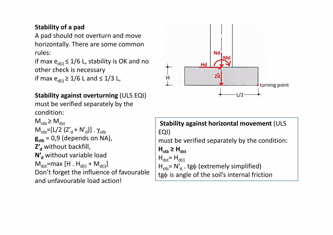
Footing pad and strip under a wall
A pad is bended in both perpendicular directions x and y.
A strip is bended direction x only can be solved as a pad (strip) with breath of 1 m.This is valid both for geotechnical and structural design!
The wall can be of masonry or reinforced concrete

Design of a pad (strip under a wall) as a structure
First of all should be mentioned, that a part of contact pressure z is responsible for pad stressing, only! Hold true:
effective (upward) pressure pz = z ‐ qz, (sometimes will be marked as pd) ‐ Pad „floats“ in the soil.where qz = Zd/(B . L)
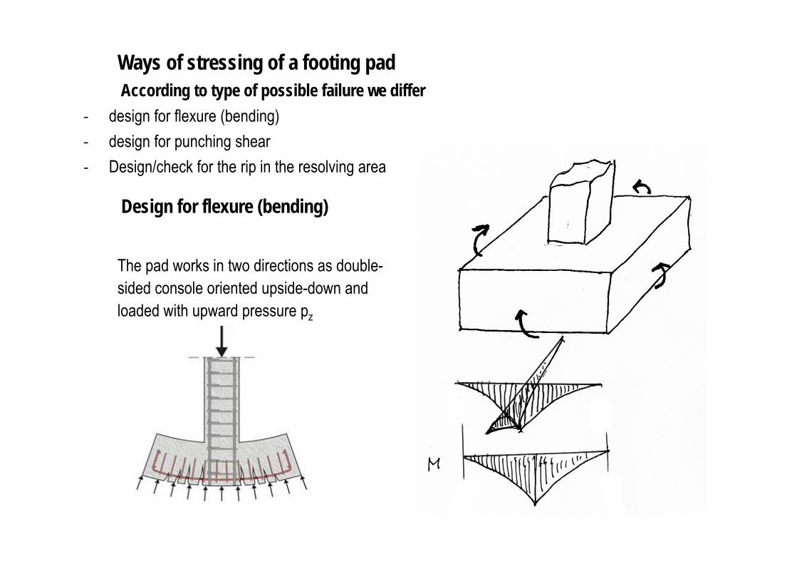
Ways of stressing of a footing padAccording to type of possible failure we differ
‐ design for flexure (bending)‐ design for punching shear‐ Design/check for the rip in the resolving area
Design for flexure (bending)
The pad works in two directions as double-sided console oriented upside-down and loaded with upward pressure pz

Acting flexural moment MEd = - ½ pEd . Lef2
for 1 m of breath or MEd = - ½ pEd . lef
2 . Bfor the total breath B
Resisting flexural moment MRd = Ast . fyd . (d-0,8x/2) for a rectangular cross-section.Regular review for a bended cross-section should be provided!
Do not forget (do it firstly) the check of As ≥ As,min
As,min = 0,026 .fctm.bt . d/fyk,but not less than: 0,0013. bt . dWhere mean effective depth d = (d1 + d2)/2for bt use booth B and L (check both directions x, y)!Pads due to relatively large height H (compared to hsby slabs) can easy run to the range of under-reinforced concrete.
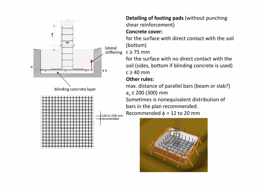
Detailing of footing pads (without punching shear reinforcement)Concrete cover:for the surface with direct contact with the soil (bottom)c ≥ 75 mmfor the surface with no direct contact with the soil (sides, bottom if blinding concrete is used) c ≥ 40 mmOther rules:max. distance of parallel bars (beam or slab?)as ≤ 200 (300) mmSometimes is nonequivalent distribution of bars in the plan recommended.Recommended = 12 to 20 mm

Anchoring of bars at the end of a pad. It is relatively complicated, based on strut and tie model.Original theory is based on the elastic presumption of pd distribution. There is no reason why not to keep the model of design with uniform distribution of pdof a part of contact area (Aef). In the EN1992‐1‐1 can be seen:

where:R is the resultant of upward pressure within distance xze is the external lever arm, i.e. distance between R and the vertical force NEd. Can be assumed e =
0,15b.NEd is the vertical force corresponding to total ground pressure between sections A and Bzi is the internal lever arm, i.e. distance between the reinforcement and the horizontal force Fc, zimay be taken as 0,9d. Fc is the compressive force corresponding to maximum tensile force Fs,max
For straight bars without end anchorage the minimum value of x is the most critical. As a simplification xmin= h/2 may be assumed. For other types of anchorage, higher values of x may be more critical.

where:
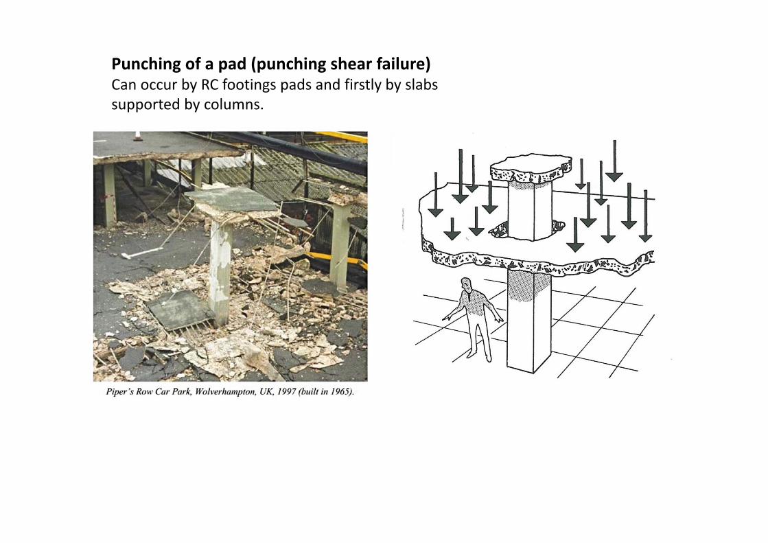
Punching of a pad (punching shear failure)Can occur by RC footings pads and firstly by slabs supported by columns.

Punching of a pad (punching shear failure)
The condition of reliability must be fulfilled:vRdc ≥ vEdThe “v” is in both cases specific value of the shear force per 1m of control perimeter. The question is how to calculate them?

Punching of a pad (punching shear failure)
The condition of reliability must be fulfilled:vRdc ≥ vEdThe “v” is in both cases the specific value of the shear force per 1m of control perimeter. The question is how to calculate them? For the value of ved, there is a problem, there. Over there is present influence of bending moment Mtotal = Md+ Hd *H.The moment increases and decreases the value of vEd, see the next figure.
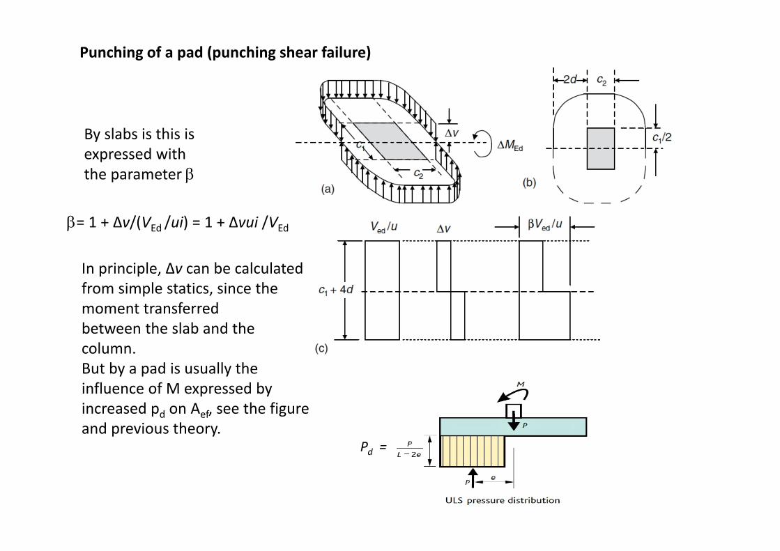
By slabs is this isexpressed with the parameter
= 1 + Δv/(VEd /ui) = 1 + Δvui /VEd
In principle, Δv can be calculated from simple statics, since the moment transferredbetween the slab and the column. But by a pad is usually the influence of M expressed by increased pd on Aef, see the figure and previous theory.
Pd =
Punching of a pad (punching shear failure)

How to solve the „punching“ issue by footing pads? (punching shear failure)
By footings is the principle same but there are some important differences here:1. The influence of bending M is expressed differently. See previous slide.2. Footings are thicker when compared to slabs.3. By footings it is strongly recommended to change the design, not to use special reinforcement.
By Eurocodes is punching of footings not solved into details, now. Two major ways can be seen:A) Usage of the full theory used for slabs.(With lace problems)B) Usage of simplified techniques for verification of not punching, only.
By this example is presumed the critical (control) perimeter should be find in the distance between (d, 2d). But the ratio H/B is absolutely outside the recommended range –see nextslide.

Simplified technique for punching review designed by lecturerPresumptions:
• Influence of bending moment is expressed by increased pd.
• The punching force is calculated from part of the area Aeff outside the controlperimeter. The area is reduced by 2ed (as usual) or not.
• The control perimeter is in the distance of d outside the column plan contour.
• For the resistance calculation vRdc are used Eurocode principles and rules valid for shear (there are in the principle equal with punching).


How to increase the pad resistance against punching?‐ increase the pad height H.‐ increase the concrete strength class.‐ use stepped or slope pad (as last).
Reinforcement against punching

(principles only)

Footing strip under a wall – difference to a padA pad is bended in both perpendicular directions x and y.A strip under a wall is bended in thedirection x only can be solved as a pad (strip) with breath of 1 m. (The wall is stiff in its plane „y‐z“.)This is valid both for geotechnical and structural design!
The material of the wall implies the rigidity of the wall – masonry connection and the character of contact and upward pressure distribution shape.
masonry wall RC wall
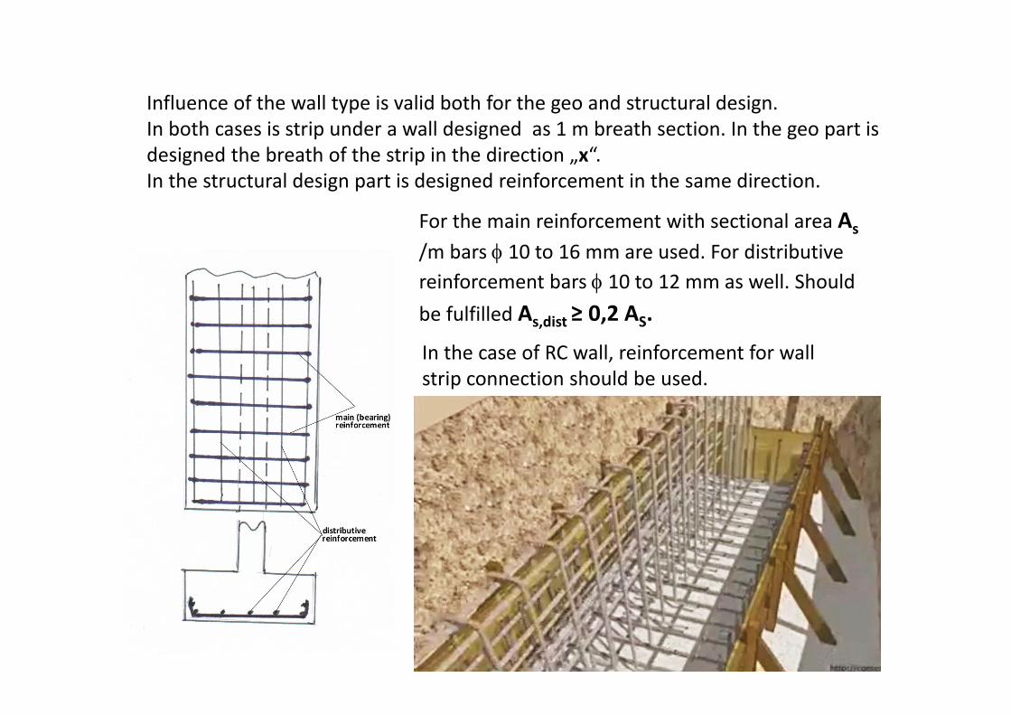
Influence of the wall type is valid both for the geo and structural design.In both cases is strip under a wall designed as 1 m breath section. In the geo part is designed the breath of the strip in the direction „x“.In the structural design part is designed reinforcement in the same direction.
For the main reinforcement with sectional area As/m bars 10 to 16 mm are used. For distributive reinforcement bars 10 to 12 mm as well. Should be fulfilled As,dist ≥ 0,2 AS.
In the case of RC wall, reinforcement for wall strip connection should be used.

In special cases, if large opening in a wall exists, additional reinforcement in longitudinal direction (y) should be applied.
Calculated reinforcement must be in an effective position in cross‐section! By bended members it is the part of cross‐section in tension (0,25 h).
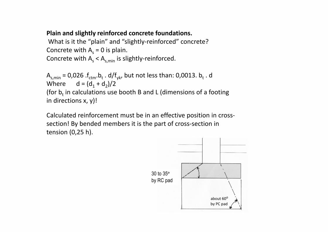
Plain and slightly reinforced concrete foundations.What is it the “plain” and “slightly‐reinforced” concrete?Concrete with As = 0 is plain.Concrete with As < As,min is slightly‐reinforced.
As,min = 0,026 .fctm.bt . d/fyk, but not less than: 0,0013. bt . dWhere d = (d1 + d2)/2(for bt in calculations use booth B and L (dimensions of a footingin directions x, y)!
30 to 35ᵒ by RC pad
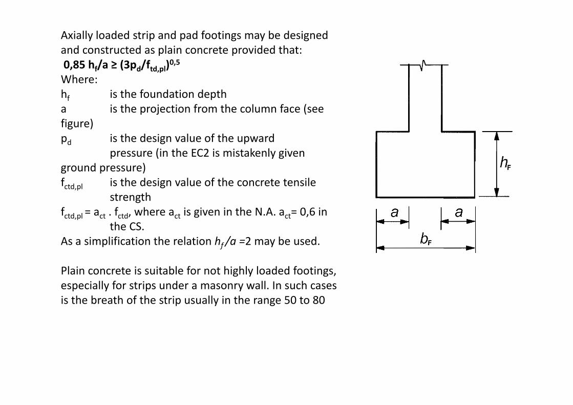
Axially loaded strip and pad footings may be designed and constructed as plain concrete provided that:0,85 hf/a ≥ (3pd/ftd,pl)0,5Where:hf is the foundation deptha is the projection from the column face (see figure)pd is the design value of the upward
pressure (in the EC2 is mistakenly given ground pressure)fctd,pl is the design value of the concrete tensile
strengthfctd,pl = act . fctd, where act is given in the N.A. act= 0,6 in
the CS.As a simplification the relation hf /a =2 may be used.
Plain concrete is suitable for not highly loaded footings, especially for strips under a masonry wall. In such cases is the breath of the strip usually in the range 50 to 80

Footing strip under a row of columns
Field of usage:‐ when the pads tend to be too large (weak soil, high load),‐ when limiting of the differential settlement is necessary,
Geotechnical design of a footing strip under a row of columnsin simplified variant is similar technique to a pad used.Force quantities in „Sumas“ are used
ed(i) =( ΣMd(i) + ΣHd(i) . H)/ (ΣNd(i) + Zd)z(i) =(ΣNd(i)+ Zd)/(B. (L‐2ed(i))) ≤ RdFor i = 1 ,2, 3