
Part 1 WAVED LINE PATTERNS Chapter 1 ON SURFACES Vol.VI 2nd Ed. Part 1... · markedly similar...
17
Introduction The following notes were produced by Holtzapffel & Co; they are undated but were probably issued around 1920. They describe an ingenious way of using a standard ornamental turning lathe, with the addition of certain special equipment, to produce patterns similar to those made on a rose- engine. The lathe headstock is set up with the spiral apparatus with its extension for surface spirals and the reciprocator. The eccentric chuck is mounted on the headstock in the horizontal plane and it rocks from side to side under control of the reciprocator. A special drilling head is mounted on the nosewheel of the chuck and driven from the overhead. The spiral apparatus is connected by a long drive shaft to the leadscrew of the slide-rest. A special copy of the mandrel nose on a square stem is held in the toolbox of the slide-rest and the rectilinear chuck mounted on this. The work is mounted on the rectilinear chuck either alone or in combination with the dome chuck and/or the oblique chuck. As the slide-rest leadscrew is advanced, so the drill, oscillating up and down, cuts a waved line in the surface of the work. This and many other papers in this book have been re-typed as the original typescripts, when reproduced in print, were difficult to read. Part 1 Chapter 1 WAVED LINE PATTERNS ON SURFACES Part 1 15-06-2013
Transcript of Part 1 WAVED LINE PATTERNS Chapter 1 ON SURFACES Vol.VI 2nd Ed. Part 1... · markedly similar...

IntroductionThe following notes were produced by Holtzapffel & Co; they are undated but were probably
issued around 1920. They describe an ingenious way of using a standard ornamental turning lathe,with the addition of certain special equipment, to produce patterns similar to those made on a rose-engine.
The lathe headstock is set up with the spiral apparatus with its extension for surface spirals andthe reciprocator. The eccentric chuck is mounted on the headstock in the horizontal plane and it rocksfrom side to side under control of the reciprocator. A special drilling head is mounted on thenosewheel of the chuck and driven from the overhead. The spiral apparatus is connected by a longdrive shaft to the leadscrew of the slide-rest.
A special copy of the mandrel nose on a square stem is held in the toolbox of the slide-rest and therectilinear chuck mounted on this. The work is mounted on the rectilinear chuck either alone or incombination with the dome chuck and/or the oblique chuck. As the slide-rest leadscrew is advanced,so the drill, oscillating up and down, cuts a waved line in the surface of the work.
This and many other papers in this book have been re-typed as the original typescripts, whenreproduced in print, were difficult to read.
Part 1Chapter 1
WAVED LINE PATTERNSON SURFACES
Part 1
15-06-2013

IntroductionThe Rose Chuck enables rose engine work to be undertaken without the need for a rocking head
stock or rocking, or sliding slide-rest. It has horizontally opposed slides pushed by springs such thatthe workpiece may oscillate from side to side under the control of a rosette. To avoid sudden stopsand starts occasioned by the rubber slowing before and accelerating after passing over a crest on therosette, it was found necessary to use the tangent screw to regulate the rotation speed of the chuckand, for this purpose, an Automatic Driving Apparatus was devised.
The Pumping Apparatus comprises a strong spring which pushes against a rosette, fixed on thetail-end of the traversing mandrel, against a follower, screwed into the back of the headstock casting,such that the workpiece is advanced towards the cutter, causing it to cut successively deeper andshallower. However, as the automatic driving apparatus could not be engaged when the mandrel wastraversing, the Variable Drive was devised to impart a steady slow motion to the lathe in order toobtain a fine finish from a rotating cutter.
The following Notes on the Rose Chuck and Pumping Apparatus were published byHoltzapffel & Co., c.1892 and they describe the setting up and operation of Mr Budd’s RoseChuck. There were two editions; the second included sections on Cutters and Cutting Framesand The Rose Chuck & the Spiral Apparatus. The two editions have been amalgamated here,causing some confusion with figure numbers.
There follows two extracts from ‘Engineering’ magazine volume XLI dated 25th June 1886featuring the Rose Chuck as made by Holtzapffel & Co., and a further extract from the same magazine,volume LIVdated 19th August 1892.
Finally, there are two Letters Patent registered by Budd in 1885, which include detaileddrawings of the Rose Chuck; and a further Patent for Silent Driving Gear for the Slide-rest registeredin 1888.
The original typescripts were difficult to read so they have been re-typed for this book.
Part 1Chapter 2
BUDD’S ROSE CHUCK &PUMPING APPARATUS
Holtzapffel Lathe No. 2245with workpiece

Introduction
Part 1Chapter 3
A Straight Line/Eccentric Chuck combination made by John Bower(photographs courtesy Lynn Woodwork Museum, New Zealand)
The following notes are of unknown origin but believed to be part of an instructionhandbook produced by Holtzapffel & Co, for buyers of their rare Rose Engines. A PlateNumber is missing from the first page of the manuscript, but the text refers to a Plate numbered15. It is therefore assumed that the original manuscript is a draft for a booklet for which theplate numbers had yet to be finalised. It is also clear that this is only part of what was intendedto be a larger publication. It was Holtzapffels’ practice to have handbooks of this typeproduced in manuscript form when they were provided only to a small clientele where the costof printing a small run would be prohibitive. This extract may have been either a draft or partof a master copy which would have been provided to a hand copyist for production of eachindividual handbook.
As the handwritten manuscript is difficult to read a typed copy of the text is also included.
THE STRAIGHT-LINECHUCK & THE PILLAR
FLUTING CHUCK

IntroductionThis typescript is presumed to have been copied from a manuscript written by George William
Budd and although undated is believed to have been written before 14th October 1897 when Buddadopted the surname of Holtzapffel-Budd. It describes the Rosette Forming Machine designed andmade, largely from spare parts available around the workshop, by Charles Holtzapffel about 1840.It remained in constant use until the manufacturing business closed in 1927. For the convenience ofreaders the text has been re-typed.
The machine has been held in the London Science Museum since 1928. The monochromephotographs were provided by the Science Museum in 1952 when this typescript is thought to havebeen produced.
Part 1Chapter 4
THE ROSETTE FORMINGMACHINE
photograph courtesy the Science Museum, London
Holtzapffel & Co employed a numbering system to catalogue the shapes of their rosettes andthese were illustrated in a booklet supplied to buyers of their Rose Cutting Frame. (The booklet isreproduced in Part 1. Chapter 11. below) together with computer simulations of Holtzapffel rosetteprofiles, kindly provided by Bill Ooms, and notes by the Compiler about M. de la Condamine’sRosette Designing Instrument. For further information see L’Art duTourner 2nd Edition byC.Plumier (translated into English by Dr. Paul Ferraglio) and the Bulletin of the Society ofOrnamental Turners (edition #52 page 73) where Dr. Ferraglio explains the most important partsof a presentation by M. de la Condamine to the Royal Academy of Science, Paris, 1734, in whichde la Condamine considered ‘The Relationship between Rosettes and the Patterns they canproduce. This is a most useful paper as it gives practical advice on how to take a small pattern,such as the outline of a human head, and generate from it a larger rosette that will reproduce on thework-piece the pattern in its original size.

Introduction John Thomas Bower was born in Kirriemuir, near Forfar in Scotland around 1795-6. Hemoved eventually to London where he conducted his business as engine-lathe and toolmaker, at 13 King Street,Clerkenwell. He was one of the most skilful makers of ornamental turning lathes and rose engines both foramateurs and for the jewellery and other engine-turning trades, and his rose engines and combined rose-engine/ornamental-turning lathes are among the finest ever made. Each of his O.T. & R.E. lathes is different butthe characteristics of his work are easily recognisable. John Bower died on 25th August 1849.
He was employed from time to time to convert Holtzapffel O.T. Lathes into Rose Engines; one of these,No.930, is stored by the Museum of Transport in Glasgow. Holtzapffel Rose Engine Lathe No.1110, a full-blown 12” Rose Engine, was purchased originally by the Earl of Harborough on 15th December 1831, and islisted in Holtzapffel’s register as being sold for £330. It appears that John Bower may have been the secondowner of this lathe and he is reported to have said that the total cost of the outfit with all its many accessoriesamounted to £1500 and, when it came into his possession, it had with it almost every contrivance which anamateur could possibly desire; and a great deal besides. It included two Geometric Chucks and a Medallion-copying device. It is speculated that John Bower may have been inspired by this lathe to make what is possiblyhis finest creation, the superb Rose Engine & O.T. Combination Lathe, owned by the Lynn Woodwork Museumin New Zealand.
Bower made several O.T/Rose-Engine-Combination-Lathes, some of which are shown in the followingpages. Each one is different but Bower’s inimitable style is obvious in all of them. Jno. Muckle made lathes ofmarkedly similar design c.1830 and the Compiler suspects that Bower and Muckle may have worked together atsome time. John Bower is believed to be the inventor of the ‘single rosette carrier’ attachment for fitting to thetail of the mandrel of an ornamental turning lathe. James Munro adopted Bower’s design for his ‘single rosette’rose engine and Henry Smith Frost used this design for the later Rose Engine Conversions he carried out onHoltzapffel lathes.
Part 1Chapter 5
BOWER’S ROSE ENGINECONVERSION
photograph courtesy the Lynn Woodwork Museum, New Zealand

Rocking Slide-Rest made by W. J. Evansfor lathe No. 1217
(photograph courtesy of a previous owner)
A NEW APPARATUS FOR THEEXECUTION
OF TRUE ROSE ENGINE TURNING ON
THE ORDINARY ORNAMENTAL LATHE
C. H. CHAPLIN
1933
Part 1Chapter 6
Introduction:A New and Simple Means of Executing Real Rose Engine Turning with Simple
Apparatus. Designed by C.H.Chaplin 22nd May 1933 published by the author and sold forfive shillings.
Although Chaplin claimed this as a new invention it appears, perhaps unconsciously, tohave been based on one of several machines invented many years earlier. A similar apparatuswas described in Manuel du Tourneur (1816), a slide-rest following this principle (shownbelow) was made by W.J.Evans around 1870 for what was possibly his most comprehensivelathe, No.1217, and another was made, presumably by Holtzapffel & Co., for the Rev.C.C.Ellison’s lathe No.1911.The Rev. C. C. Ellison demonstrated the advantage of a rocking spherical slide-rest over therocking headstock; namely, that it could produce a regular series of patterns on a curve,whereas the patterns produced by a rocking headstock change because the effect of therocking action gradually increases as the slide-rest moves around the curve towards the latheaxis.
Chaplin’s treatise is followed by pictures of a miniature Rocking Slide-rest lathe.
CHAPLIN’S ROCKINGSLIDE-REST

IntroductionRichard Pudsey-Dawson’s Geometric Slide-Rest has been well described in the book:
‘Ornamental Turning’ by J. H. Evans. It comprises an ornamental slide-rest with an additionalslide, parallel to and sitting on top of the main slide; this extra slide has a leadscrew of 10 t.p.i. Andis used to set the cutter at the desired radius from centre. In place of the normal leadscrew, themain slide has a spring, that pulls its carriage towards the operator; there is an attachment thatclamps over the end of the main slide to hold a cam or template; a steel arm fixed to the main-slidecarriage bears a rubbing wheel that is held, by the pressure of the spring, against the cam so that, asthe cam is rotated, the sprung slide oscillates towards and away from centre. The cam-holder isjoined by a shaft (made flexible by universal joints) to the gear-train of the spiral apparatus which isso arranged that the cam will rotate an exact number of turns to one turn of the lathe mandrel.
One of the most popular of the rose-engine patterns is made by the rosette described underHoltzapffel’s numbering system as ‘F4’. This rosette was formed by a the cutter following a heart-shaped cam rotated four times to one rotation of the rosette blank. Pudsey Dawson’s apparatusincludes a heart-shaped cam for this purpose; and here is the great advantage of this slide-rest: bychanging the ratio of the gear-train, this one cam may do the work of several rosettes: F3, F4, F5,F6, F8, etc. Cams of several other shapes were provided, including: eccentric circle, ellipse, etc.,and they are so easy to make that their variety is constrained only by the user’s imagination. Theonly disadvantage of this machine is that it does not simulate the pumping action of a rose engine;however, this could be arranged without too much difficulty by adapting the drive to operate at anyangle up to 90° from its normal position across the bed; at around 45° it would simulate both therocking and pumping motions simultaneously.
Pudsey-Dawson took out Letters Patent for his invention and these are copied here to assist thereader in understanding the apparatus and, perhaps, to make it. Pudsey-Dawson made at least oneof these slide-rests himself; others were made under his patent by W.J.Evans and later by his son,J.H.Evans. There are more photographs at the end of this Chapter and an extract from EnglishMechanics magazine, December 1871, describing this apparatus.
The Pudsey-Dawson Geometric Slide-rest made by J.H.Evans.
PUDSEY-DAWSON’S GEOMETRICSLIDE-REST
Part 1Chapter 7

Introduction This is an article from the ‘Model Engineer’ magazine, volume 65 dated24th December 1931 describing a Geometric Slide-rest exhibited at the recent ModelEngineers Exhibition by the maker, Granville Morton Grace, B.A., BSc. It is followed byan undated treatise on the instrument written by Grace himself. It is believed he made fiveof these rests and no two appear to be exactly the same; some of the different features maybe seen in the.photographs.
G.M.Grace was the brother of Rev. Gilbert Allan Grace, the author of ‘The Art andCraft of Ornamental Turning’ and the compiler of a limited edition book of photographsentitled ‘Ornamental Turning Design’. Most of these photographs are reproduced in Part4, Chapter 4, and the remainder are scattered around as space fillers and the reader mayfind them by consulting the Index.
A fine Grace Geometric Slide-rest in fitted mahogany chest. Note the two cams on the rearof the shaft at the left: the front cam is followed by a lever, with the facility of amplitudeadjustment, which pulls the cutter from right to left against the resistance of the long‘ribbon’ spring across the front of the rest; the rear cam is a ‘swash plate’ that is followedby a lever that pulls the cutter away from the work against the resistance of the coil-springon the central, cutting-frame-shaft. These two movements can be effected simultaneously,simulating both ‘rocking’ and ‘pumping’ motions, unlike Pudsey-Dawson’s inventionwhich had no ‘pumping’ action. The drive is connected to the spiral apparatus throughone of a pair of bevel gears so the slide-rest may be mounted either across the bed forsurface patterns or parallel for cylinder work.
Part 1Chapter 8
GRACE’S GEOMETRICSLIDE-REST

IntroductionFollowing the success of Pudsey-Dawson’s invention, George Birch of Manchester
introduced an improved version of the apparatus which he patented in 1891. This chapterincludes the Letters Patent with drawings. It also includes photographs of a simpler form ofthe device on McNab’s Birch lathe No.562.
Birch’s adaptation of the Geometric Slide-rest. This machine was devised to fit onto Birch’stwin mandrel lathe. It has a drive-shaft running along the back of the lathe with either one ortwo cam-holders mounted on the back end of the lathe saddle and pivotting rods for pushing thesprung slide at whatever angle it is set in relation to the lathe axis. Both mandrels are driven through a gear train so that, while the the front mandrel rotates once,the back completes the chosen number of revolutions. The back mandrel drives a splined shafton which is mounted a rosette, template or cam of large amplitude. The spline allows the lathesaddle with its rocking arms to be moved nearer to, or further away from the headstock. Rubbersfollow the profiles of the rosettes causing the rocking arms to rock; these arms each comprise aslide with a leadscrew, the nut of which pivots on a pillar fixed to the back of the lathe saddle; ithas a rubber at the upper end and a pushing arm at the lower end. By turning the rocking armleadscrew, to increase or decrease the distance between the rubber and the pivot, the upper endof the arm can be made the same length as, or longer than the lower end, thus determining theamplitude of movement. The pushing arms are telescopic; one is connected to the sprung slideof the geometric slide-rest and its length may be adjusted and fixed to suit any radius of the slide.The socket of the slide may be released to swivel as well as slide; then the second pushing armmay be connected and the pattern influenced by both rosettes simultaneously; or the slide may beset to an angle and a pushing arm connected to a crank to give a ‘pumping’ effect..
Part 1Chapter 9
BIRCH’S ROSE ENGINEATTACHMENT
photograph courtesy of the owner
Birch twin-mandrel
GeometricLathe

ROBINSON’S HARMONICLATHE
IntroductionThis is an apparatus for producing turned solids, the outlines of which are the
curves, known as Lissajou’s, formed by the combination of two simple harmonicmotions at right angles to one another.
In it the cutting tool is given the combined motion and so cuts the curves directlyon the revolving work. The work is mounted on an ordinary ornamental latheheadstock, and a bracket bolted to the end of the bed carries a short transverse shaft,the front end of which has a crank with a pin adjustable radially from 0 to 2.5 inches.The crank pin engages with a hole in a block that slides in a vertical slot formed in agun-metal frame, to which is bolted a long horizontal steel bar which is thus movedbackwards and forwards with a simple harmonic action as the crank rotates. The crankshaft is driven through bevel and spur gearing from an upper shaft, which is driven byhand. The ratio of the speeds of these two shafts can be varied by using wheels ofdifferent sizes.
A compound slide rest is fitted to the bed and for this class of work the saddle isdetached from the leading screw nut so that it can slide independently. The tool-holder slides in transverse guides on the saddle, and has a vertical slot and blockadjustably attached to it, with which engages a crank pin fitted to a short shaftmounted in bearings on the saddle. This shaft is driven by a universally-jointed squareshaft which passes through the square hole of the upper shaft on the left-hand bracket,so that the tool-holder is caused to move transversely with a simple harmonic motionat the same time that the saddle itself is moved by being clamped to the long bardriven by the main crank. The transverse crank is adjustable in length, and it can beclamped in any angular position relative to its driving shaft, and thus to the maincrank. The tool can be set to the required depth by a screw and stop. The twoharmonic motions may thus be of any relative amplitude, speed and phase.
The outline of the work is formed by one half of a double-looped curve, and toproduce it the main crank must be turned backwards and forwards over one half of itscircle only. The example shown in the lathe is formed of two motions havingamplitudes of 3 in and 5 in, a speed ratio of 1 2, and a phase angle of 60°.
Following the death of H.C. Robinson the lathe was presented to the ScienceMuseum of London by the executors..
This notice and the following photographs are reproduced by courtesy of theScience Museum of London.
Part 1Chapter 10
space filler
Previously unpublishedphotograph believed to be by
Holtzapffel & Co.and the Compiler’s attempts
to emulate it.

THE ROSE CUTTING FRAME(and the miniature high speed cutter)
fied type of Rose Cutting Frame (see the finalpage of this Chapter) which follows theprinciples of the Pudsey-Dawson GeometricSlide-Rest but the head of the cutting framecomprises a horizontal slide with a springwhich presses a rubber against a rotating cam,thus avoiding the great expense of a dedicatedslide-rest with a sprung slide.
The Armbruster Miniature Universal Cutting Head
IntroductionThe small booklet re-
produced on the followingpages was supplied with theRose Cutting Frame. Reproduced here, it showsthe numbering system em-ployed by Holtzapffel & Co.,to catalogue the shapes oftheir rosettes. Examples of thepatterns possible with eachrosette are followed bycomputer simulations kindlyprovided by Bill Ooms ofArizona and notes by theCompiler about M. de laCondamine’s RosetteDesigning Innstrument.
As originally designed, theRose Cutting Frame is oflimited use because it can onlyproduce patterns with a fixedtool and it is insufficiently
photograph courtesy Fred Armbruster
Part 1Chapter 11
robust to do much more than scratch thesurface of the work.
J.H.Evans, observing thisdisadvantage, designed a series ofminiature cutting heads, each rotating ona shank that fits into the tool box of theinstrument and one of these is driven atspeed from the overhead. The miniatureheads made by Evans comprised aneccentric cutter, an internal cutter, adrilling spindle and a stylus.
Evans seems not to have designed aHorizontal Cutting Head; but thisdeficiency was remedied recently byFred Armbruster of Maine, USA., whodevised and made the miniatureUniversal Cutting Head shown here.
This miniature Cutter turns theRose Cutting Frame into a small butvery effective rose-engine which iscapable of work beyond the scope ofall but the most sophisticated traderose-engines which have apparatus forornamenting any point on a curvedsurface; such as on the ornamentedeggs made by Fabergé. This type ofwork is made possible on the ordinaryornamental turning lathe by theMiniature Universal Cutting Head inconjunction with either the Sphericalor the Elliptical Slide-Rest.
J.H.Evans also designed a simpli-

a spacer between them withthe pins inserted throughmatching holes). The pinsmay be spaced closely orwidely and at varying radiifrom the centre. A roller rub-ber or a curved rubber, insert-ed in one of the grooves,follows from one pin to thenext, causing the slide-rest torock to a greater or lesser de-gree as governed by the spac-ing of the pins. An infinitevariety of shapes may beformed by planned or randomchanges of the positions of thepins.
The poor quality of theoriginal print necessitated atyped copy being provided toassist the reader. Some partsof the figures and some meas-urements were so indistinct asto be impossible to decipherand these have been estimat-ed.
This drawing was made bythe late Alan Campbell andpublished in S.O.T. Bulletin#34. Alan owned a headstockconstructed in the reversemanner to the one in the Me-chanics Magazine article, inthat the headstock rocks be-tween fixed arms and theslide-rest is fixed.
Introduction: This article is in the form of a letter from ‘R’ of Halifax to the MechanicsMagazine, Museum Register, Journal and Gazette and published by them on 28th June 1834. Itdescribes a mechanism invented by a Mr. Child, comprising a fixed headstock with a universalrosette and a rocking slide-rest. The rosette comprises a disc with two deep grooves on its edgeand the spaces within the grooves may be bridged by pins located in rows of indexed holes(giving the same effect as would a pair of identical division plates with
Part 1Chapter 12
CHILD’S UNIVERSAL ROSETTE

Part 1Chapter 13
MASSA’S UNIVERSAL LATHEExtracts from old magazines are difficult to read, so forthe convenience of readers many have been re-typed.
IntroductionIn 1887 F. N. Massa of New Jersey, USA, used the Birch variation of Pudsey-Dawson’sinvention to make what he described as a Universal Lathe. This versatile lathe isdescribed in the following extracts from English Mechanic magazine of that time.
English Mechanics 18thNovember 1887
issue 1182 page 280 Ref. 28120 MASSA’S UNIVERSAL
LATHEDuring the past three years the
writer, debarred from businesspursuits by broken health, hasoccupied his time in constructingsome additions, and makingalterations to a Holtzapffel ornamentallathe. The lathe had the unusualfeature of "pillars" and a "yoke" toreceive end thrust, the "yoke"swinging off when mandrel traversed.The changes were made with verylittle interference with existingfunctions. The only metal removedwas at edges of bed, where angles of60" were planed, small rebates insidebed to clamp the heads, and roundingthe square holes in ends of bed, toplace the guide screw centrally. Theheads were raised enough to use the5in. slide-rest on the new saddle, butfinally new metal working sphericaland ornamenting rests were made,with special features to suit the newconditions. A full-length, light bedwas put at back, parallel, lower, and10in. from centres, with traversingmandrel and plain poppet. In front ofmain bed is the rack, along which thesaddle is moved by an annular wheeland pinion and two more wheels; onthe rack is a steel scale for quickadjustment. The guide screw ispartly covered; it has a split nut, invertical slides, worked by eccentriccam, as is usual. The screw issecured at the left only. Inside of theleg frames are inlaid in contact withends of bed, iron plates with bossespassing through to the leg surfaces.The right-hand boss is bored toreceive the screw shaft, which passesthrough, and has a handle fitted on theend. The left boss is bored out much
(Continues)
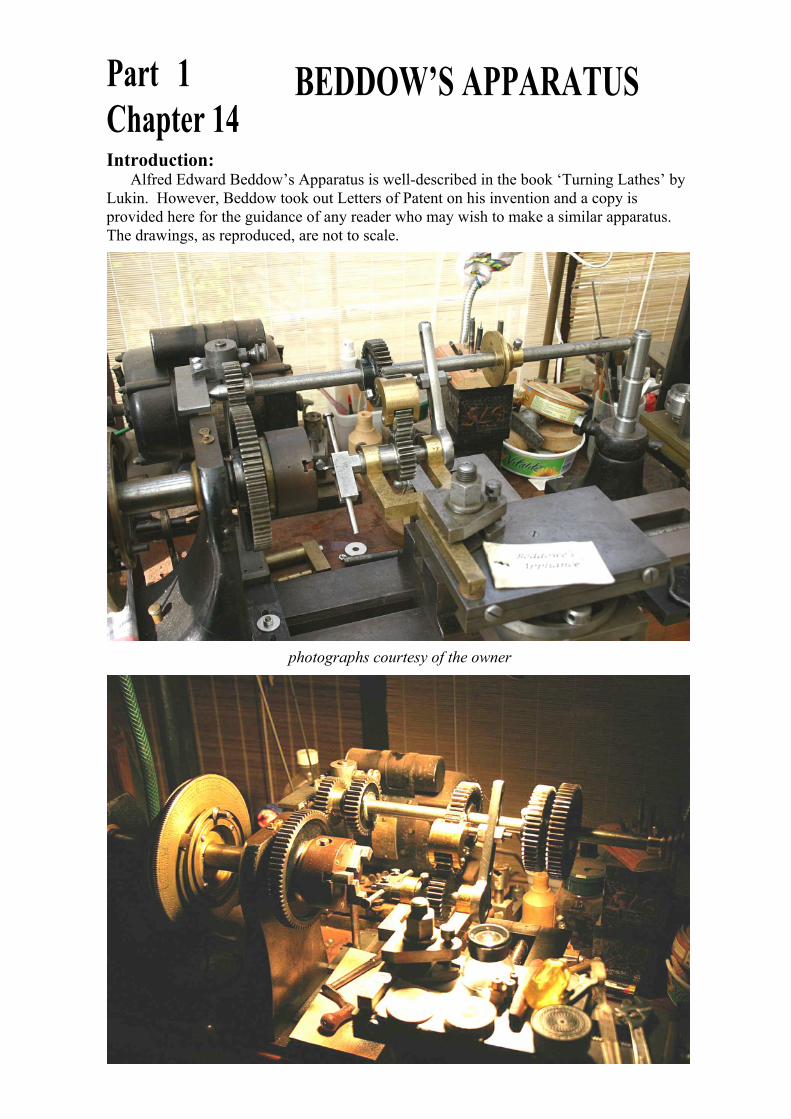
Introduction:Alfred Edward Beddow’s Apparatus is well-described in the book ‘Turning Lathes’ by
Lukin. However, Beddow took out Letters of Patent on his invention and a copy isprovided here for the guidance of any reader who may wish to make a similar apparatus.The drawings, as reproduced, are not to scale.
Part 1Chapter 14
BEDDOW’S APPARATUS
photographs courtesy of the owner
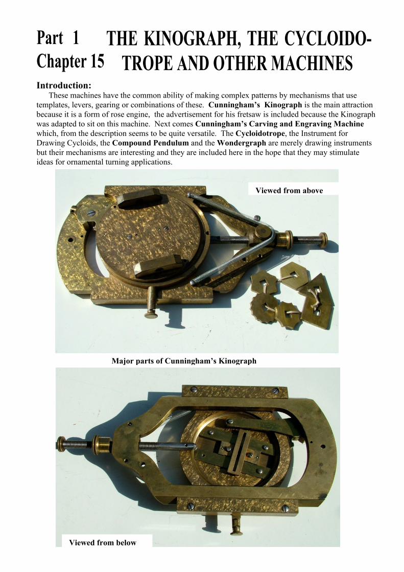
Introduction:These machines have the common ability of making complex patterns by mechanisms that use
templates, levers, gearing or combinations of these. Cunningham’s Kinograph is the main attractionbecause it is a form of rose engine, the advertisement for his fretsaw is included because the Kinographwas adapted to sit on this machine. Next comes Cunningham’s Carving and Engraving Machinewhich, from the description seems to be quite versatile. The Cycloidotrope, the Instrument forDrawing Cycloids, the Compound Pendulum and the Wondergraph are merely drawing instrumentsbut their mechanisms are interesting and they are included here in the hope that they may stimulateideas for ornamental turning applications.
Major parts of Cunningham’s Kinograph
Part 1Chapter 15
THE KINOGRAPH, THE CYCLOIDO-TROPE AND OTHER MACHINES
Viewed from above
Viewed from below
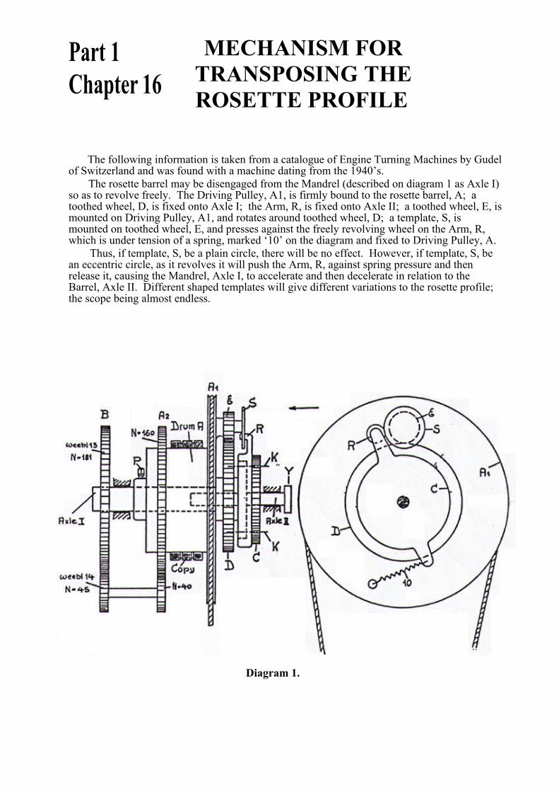
MECHANISM FOR TRANSPOSING THE ROSETTE PROFILE
The following information is taken from a catalogue of Engine Turning Machines by Gudelof Switzerland and was found with a machine dating from the 1940’s.
The rosette barrel may be disengaged from the Mandrel (described on diagram 1 as Axle I)so as to revolve freely. The Driving Pulley, A1, is firmly bound to the rosette barrel, A; atoothed wheel, D, is fixed onto Axle I; the Arm, R, is fixed onto Axle II; a toothed wheel, E, ismounted on Driving Pulley, A1, and rotates around toothed wheel, D; a template, S, ismounted on toothed wheel, E, and presses against the freely revolving wheel on the Arm, R,which is under tension of a spring, marked ‘10’ on the diagram and fixed to Driving Pulley, A.
Thus, if template, S, be a plain circle, there will be no effect. However, if template, S, bean eccentric circle, as it revolves it will push the Arm, R, against spring pressure and thenrelease it, causing the Mandrel, Axle I, to accelerate and then decelerate in relation to theBarrel, Axle II. Different shaped templates will give different variations to the rosette profile;the scope being almost endless.
Diagram 1.
Part 1Chapter 16
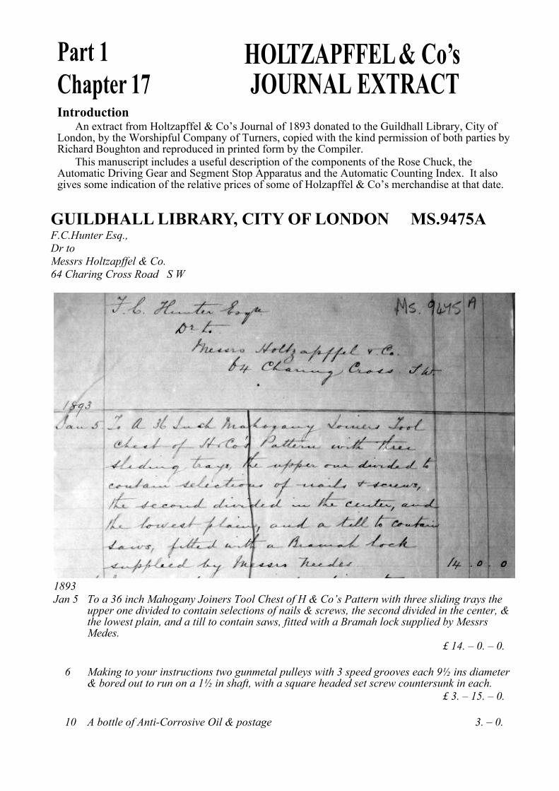
IntroductionAn extract from Holtzapffel & Co’s Journal of 1893 donated to the Guildhall Library, City of
London, by the Worshipful Company of Turners, copied with the kind permission of both parties byRichard Boughton and reproduced in printed form by the Compiler.
This manuscript includes a useful description of the components of the Rose Chuck, theAutomatic Driving Gear and Segment Stop Apparatus and the Automatic Counting Index. It alsogives some indication of the relative prices of some of Holzapffel & Co’s merchandise at that date.
Part 1Chapter 17
HOLTZAPFFEL & Co’s JOURNAL EXTRACT
GUILDHALL LIBRARY, CITY OF LONDON MS.9475AF.C.Hunter Esq.,Dr toMessrs Holtzapffel & Co.64 Charing Cross Road S W
1893Jan 5 To a 36 inch Mahogany Joiners Tool Chest of H & Co’s Pattern with three sliding trays the upper one divided to contain selections of nails & screws, the second divided in the center, & the lowest plain, and a till to contain saws, fitted with a Bramah lock supplied by Messrs Medes.
£ 14. – 0. – 0.
6 Making to your instructions two gunmetal pulleys with 3 speed grooves each 9½ ins diameter& bored out to run on a 1½ in shaft, with a square headed set screw countersunk in each.
£ 3. – 15. – 0.
10 A bottle of Anti-Corrosive Oil & postage 3. – 0.