

Oracle Fusion Middleware Programming Stand-alone Clients for ...
Contents
Preface . . . . . . . . . . . . . . . . . . . . . . . . . . . . . . . . . . . . . . . . . . . . . . . . . . . . . . . .iHow this course is organized . . . . . . . . . . . . . . . . . . . . . . . . . . . . . . . . . . . . . . . .iHow each topic is organized . . . . . . . . . . . . . . . . . . . . . . . . . . . . . . . . . . . . . . . ii
Part 1. System programming on z/OS
Chapter 1. Overview of system programming . . . . . . . . . . . . . . . . . . . . . . . 71.1 The role of the system programmer . . . . . . . . . . . . . . . . . . . . . . . . . . . . . . 81.2 What is meant by separation of duties . . . . . . . . . . . . . . . . . . . . . . . . . . . . 91.3 Customizing the system . . . . . . . . . . . . . . . . . . . . . . . . . . . . . . . . . . . . . . 10
1.3.1 z/OS system libraries . . . . . . . . . . . . . . . . . . . . . . . . . . . . . . . . . . . . 121.3.2 SYS1.PARMLIB . . . . . . . . . . . . . . . . . . . . . . . . . . . . . . . . . . . . . . . . 121.3.3 Link pack area (LPA). . . . . . . . . . . . . . . . . . . . . . . . . . . . . . . . . . . . . 131.3.4 Pageable link pack area (PLPA) . . . . . . . . . . . . . . . . . . . . . . . . . . . . 131.3.5 Fixed link pack area (FLPA) . . . . . . . . . . . . . . . . . . . . . . . . . . . . . . . 141.3.6 Modified link pack area (MLPA) . . . . . . . . . . . . . . . . . . . . . . . . . . . . 151.3.7 SYS1.PROCLIB . . . . . . . . . . . . . . . . . . . . . . . . . . . . . . . . . . . . . . . . 151.3.8 The master scheduler subsystem . . . . . . . . . . . . . . . . . . . . . . . . . . . 151.3.9 A job procedure library . . . . . . . . . . . . . . . . . . . . . . . . . . . . . . . . . . . 171.3.10 Search order for programs . . . . . . . . . . . . . . . . . . . . . . . . . . . . . . . 181.3.11 What system symbols are . . . . . . . . . . . . . . . . . . . . . . . . . . . . . . . . 19
1.4 Managing system performance . . . . . . . . . . . . . . . . . . . . . . . . . . . . . . . . . 211.5 Configuring I/O devices . . . . . . . . . . . . . . . . . . . . . . . . . . . . . . . . . . . . . . . 221.6 Following a process of change control . . . . . . . . . . . . . . . . . . . . . . . . . . . 23
1.6.1 Risk assessment . . . . . . . . . . . . . . . . . . . . . . . . . . . . . . . . . . . . . . . . 241.6.2 Change control record system . . . . . . . . . . . . . . . . . . . . . . . . . . . . . 241.6.3 Production control . . . . . . . . . . . . . . . . . . . . . . . . . . . . . . . . . . . . . . . 25
1.7 Configuring consoles. . . . . . . . . . . . . . . . . . . . . . . . . . . . . . . . . . . . . . . . . 261.8 Using SMP/E to manage changes . . . . . . . . . . . . . . . . . . . . . . . . . . . . . . 291.9 Initializing the system . . . . . . . . . . . . . . . . . . . . . . . . . . . . . . . . . . . . . . . . 31
1.9.1 Initialization process . . . . . . . . . . . . . . . . . . . . . . . . . . . . . . . . . . . . . 321.9.2 IPL types . . . . . . . . . . . . . . . . . . . . . . . . . . . . . . . . . . . . . . . . . . . . . . 371.9.3 Shutting down the system . . . . . . . . . . . . . . . . . . . . . . . . . . . . . . . . . 38
1.10 Summary . . . . . . . . . . . . . . . . . . . . . . . . . . . . . . . . . . . . . . . . . . . . . . . . . 39
Chapter 2. Using SMP/E . . . . . . . . . . . . . . . . . . . . . . . . . . . . . . . . . . . . . . . . 412.1 What is SMP/E? . . . . . . . . . . . . . . . . . . . . . . . . . . . . . . . . . . . . . . . . . . . . 422.2 The SMP/E view of the system . . . . . . . . . . . . . . . . . . . . . . . . . . . . . . . . . 422.3 Changing system elements . . . . . . . . . . . . . . . . . . . . . . . . . . . . . . . . . . . . 44
© Copyright IBM Corp. 2005, 2006. All rights reserved. 1

2.4 Introducing an element into the system. . . . . . . . . . . . . . . . . . . . . . . . . . . 442.5 Preventing problems with an element . . . . . . . . . . . . . . . . . . . . . . . . . . . . 462.6 Fixing problems with an element. . . . . . . . . . . . . . . . . . . . . . . . . . . . . . . . 472.7 Customizing an element - USERMOD SYSMOD . . . . . . . . . . . . . . . . . . . 48
2.7.1 Prerequisites and corequisites . . . . . . . . . . . . . . . . . . . . . . . . . . . . . 492.8 Tracking and controlling elements. . . . . . . . . . . . . . . . . . . . . . . . . . . . . . . 502.9 Working with SMP/E . . . . . . . . . . . . . . . . . . . . . . . . . . . . . . . . . . . . . . . . . 50
2.9.1 SMP/E basic commands . . . . . . . . . . . . . . . . . . . . . . . . . . . . . . . . . . 512.10 When is SMP/E used? . . . . . . . . . . . . . . . . . . . . . . . . . . . . . . . . . . . . . . 622.11 Why is SMP/E used?. . . . . . . . . . . . . . . . . . . . . . . . . . . . . . . . . . . . . . . . 632.12 Terminology. . . . . . . . . . . . . . . . . . . . . . . . . . . . . . . . . . . . . . . . . . . . . . . 63
2.12.1 Communicating with IBM Defect Support . . . . . . . . . . . . . . . . . . . . 632.12.2 Consolidate Software Inventory (CSI) and zones . . . . . . . . . . . . . . 642.12.3 Maintenance . . . . . . . . . . . . . . . . . . . . . . . . . . . . . . . . . . . . . . . . . . 65
2.13 Local SMP/E Environments. . . . . . . . . . . . . . . . . . . . . . . . . . . . . . . . . . . 672.13.1 Production, Test and Emergency Fix . . . . . . . . . . . . . . . . . . . . . . . 672.13.2 Base z/OS and Product CSIs . . . . . . . . . . . . . . . . . . . . . . . . . . . . . 68
2.14 How to use SMP/E . . . . . . . . . . . . . . . . . . . . . . . . . . . . . . . . . . . . . . . . . 682.14.1 SYSMOD. . . . . . . . . . . . . . . . . . . . . . . . . . . . . . . . . . . . . . . . . . . . . 682.14.2 JCL . . . . . . . . . . . . . . . . . . . . . . . . . . . . . . . . . . . . . . . . . . . . . . . . . 692.14.3 RECEIVE Command. . . . . . . . . . . . . . . . . . . . . . . . . . . . . . . . . . . . 692.14.4 APPLY Command . . . . . . . . . . . . . . . . . . . . . . . . . . . . . . . . . . . . . . 692.14.5 ACCEPT Command . . . . . . . . . . . . . . . . . . . . . . . . . . . . . . . . . . . . 702.14.6 LIST Command . . . . . . . . . . . . . . . . . . . . . . . . . . . . . . . . . . . . . . . . 70
2.15 ISPF . . . . . . . . . . . . . . . . . . . . . . . . . . . . . . . . . . . . . . . . . . . . . . . . . . . . 702.16 Order and download IBM fixes . . . . . . . . . . . . . . . . . . . . . . . . . . . . . . . . 742.17 Summary . . . . . . . . . . . . . . . . . . . . . . . . . . . . . . . . . . . . . . . . . . . . . . . . . 74
Chapter 3. Hardware systems and LPARs . . . . . . . . . . . . . . . . . . . . . . . . . 773.1 Overview of mainframe hardware systems . . . . . . . . . . . . . . . . . . . . . . . . 783.2 Early system design . . . . . . . . . . . . . . . . . . . . . . . . . . . . . . . . . . . . . . . . . 793.3 Current design. . . . . . . . . . . . . . . . . . . . . . . . . . . . . . . . . . . . . . . . . . . . . . 81
3.3.1 I/O connectivity . . . . . . . . . . . . . . . . . . . . . . . . . . . . . . . . . . . . . . . . . 823.3.2 System control and partitioning. . . . . . . . . . . . . . . . . . . . . . . . . . . . . 843.3.3 Characteristics of LPARs . . . . . . . . . . . . . . . . . . . . . . . . . . . . . . . . . 863.3.4 Consolidation of mainframes. . . . . . . . . . . . . . . . . . . . . . . . . . . . . . . 87
3.4 Processing units . . . . . . . . . . . . . . . . . . . . . . . . . . . . . . . . . . . . . . . . . . . . 883.5 Multiprocessors . . . . . . . . . . . . . . . . . . . . . . . . . . . . . . . . . . . . . . . . . . . . . 893.6 Disk devices . . . . . . . . . . . . . . . . . . . . . . . . . . . . . . . . . . . . . . . . . . . . . . . 903.7 Clustering . . . . . . . . . . . . . . . . . . . . . . . . . . . . . . . . . . . . . . . . . . . . . . . . . 92
3.7.1 Basic shared DASD . . . . . . . . . . . . . . . . . . . . . . . . . . . . . . . . . . . . . 923.7.2 CTC rings . . . . . . . . . . . . . . . . . . . . . . . . . . . . . . . . . . . . . . . . . . . . . 943.7.3 Parallel sysplex . . . . . . . . . . . . . . . . . . . . . . . . . . . . . . . . . . . . . . . . . 95
2 z/OS Basics
3.8 Typical mainframe systems. . . . . . . . . . . . . . . . . . . . . . . . . . . . . . . . . . . . 973.8.1 Very small systems . . . . . . . . . . . . . . . . . . . . . . . . . . . . . . . . . . . . . . 973.8.2 Medium single systems. . . . . . . . . . . . . . . . . . . . . . . . . . . . . . . . . . . 983.8.3 Larger systems . . . . . . . . . . . . . . . . . . . . . . . . . . . . . . . . . . . . . . . . . 99
3.9 Summary . . . . . . . . . . . . . . . . . . . . . . . . . . . . . . . . . . . . . . . . . . . . . . . . . 101
Chapter 4. Parallel Sysplex and continuous availability. . . . . . . . . . . . . 1034.1 Future of the new mainframe . . . . . . . . . . . . . . . . . . . . . . . . . . . . . . . . . 1044.2 What a Parallel Sysplex is. . . . . . . . . . . . . . . . . . . . . . . . . . . . . . . . . . . . 104
4.2.1 Shared data clustering . . . . . . . . . . . . . . . . . . . . . . . . . . . . . . . . . . 1054.2.2 Non-disruptive maintenance . . . . . . . . . . . . . . . . . . . . . . . . . . . . . . 106
4.3 Continuous availability of mainframes. . . . . . . . . . . . . . . . . . . . . . . . . . . 1064.3.1 No single points of failure . . . . . . . . . . . . . . . . . . . . . . . . . . . . . . . . 1074.3.2 Capacity and scaling . . . . . . . . . . . . . . . . . . . . . . . . . . . . . . . . . . . . 1084.3.3 Dynamic workload balancing . . . . . . . . . . . . . . . . . . . . . . . . . . . . . 1084.3.4 Ease of use . . . . . . . . . . . . . . . . . . . . . . . . . . . . . . . . . . . . . . . . . . . 1094.3.5 Single system image . . . . . . . . . . . . . . . . . . . . . . . . . . . . . . . . . . . . 1114.3.6 Compatible change and non-disruptive growth. . . . . . . . . . . . . . . . 1124.3.7 Application compatibility . . . . . . . . . . . . . . . . . . . . . . . . . . . . . . . . . 1124.3.8 Disaster recovery . . . . . . . . . . . . . . . . . . . . . . . . . . . . . . . . . . . . . . 113
4.4 Summary . . . . . . . . . . . . . . . . . . . . . . . . . . . . . . . . . . . . . . . . . . . . . . . . . 113
Contents 3

4 z/OS Basics

Preface
This course provides students of information systems technology with the backgroundknowledge and skills necessary to begin using the basic facilities of a mainframecomputer.
For optimal learning, students are assumed to have successfully completed anintroductory course in computer system concepts, such as computer organization andarchitecture, operating systems, data management, or data communications. They shouldalso have successfully completed courses in one or more programming languages, and bePC literate.
Note that this course can also be used as a prerequisite for courses in advanced topicssuch as compiler algorithms, or for internships and special studies.
Others who will benefit from this course include data processing professionals who haveexperience with non-mainframe platforms, or who are familiar with some aspects of themainframe but want to become knowledgeable with other facilities and benefits of themainframe environment.
When moving through this course, instructors are encouraged to alternate betweencourse, lecture, discussions, and hands-on exercises. The instructor-led discussions andhands-on exercises are an integral part of the learning experience, and can include topicsnot covered in this course.
After completing this course, students will have received:
� A general introduction to mainframe concepts, usage, and architecture � A comprehensive overview of z/OS, a widely used mainframe operating system� An understanding of mainframe workloads and an overview of the major middleware
applications in use on mainframes today� The basis for subsequent course work in more advanced, specialized areas of z/OS,
such as system administration or application programming
How this course is organizedThis course is organized in four parts, as follows:
� Part 1. “Introduction to z/OS and the mainframe environment” provides an overview of the types of workloads commonly processed on the mainframe, such as batch jobs and online transactions. This part of the course helps students explore the
© Copyright IBM Corp. 2005, 2006. All rights reserved. i

user interfaces of z/OS, a widely used mainframe operating system. Discussion topics include TSO/E and ISPF, UNIX interfaces, job control language, file structures, and job entry subsystems. Special attention is paid to the users of mainframes and to the evolving role of mainframes in today’s business world.
� Part 2. “Application programming on z/OS” introduces the tools and utilities for developing a simple program to run on z/OS. This part of the course guides the student through the process of application design, choosing a programming language, and using a runtime environment.
� Part 3. “Online workloads for z/OS” examines the major categories of interactive workloads processed by z/OS, such as transaction processing, database management, and Web-serving. This part of the course includes discussions of several popular middleware products, including DB2®, CICS®, and WebSphere® Application Server.
� Part 4. “System programming on z/OS” provides topics to help the student become familiar with the role of the z/OS system programmer. This part of the course includes discussions of system libraries, starting and stopping the system, security, network communications and the clustering of multiple systems. Also provided is an overview of mainframe hardware systems, including processors and I/O devices.
In this course, we use simplified examples and focus mainly on basic system functions.Hands-on exercises are provided throughout the course to help students explore themainframe style of computing. Exercises include entering work into the system, checkingits status, and examining the output of submitted jobs.
How each topic is organizedEach topic follows a common format:
� Objectives for the student� Topics that teach a central theme related to mainframe computing� Summary of the main ideas of the topic� A list of key terms introduced in the topic� Questions for review to help students verify their understanding of the material� Topics for further discussion to encourage students to explore issues that extend
beyond the topic objectives� Hands-on exercises intended to help students reinforce their understanding of the
material
ii z/OS Basics

iv z/OS Basics

Part 1 System programming on z/OS
In this part we reveal the inner workings of z/OS with discussions of system libraries,change management, and procedures for starting (IPLing) and stopping a z/OS system.This part also includes chapters on hardware details and virtualization, and the clusteringof multiple z/OS systems in a sysplex.
© Copyright IBM Corp. 2005, 2006. All rights reserved. 5

6 z/OS Basics

Chapter 1. Overview of system programming
1
Objective: As a z/OS system programmer, you need to know how to start the systemand how to bring it down again. You must also understand the role of z/OS systemlibraries, such as PARMLIB and linklist, and how these libraries affect the processingof z/OS. Also important is a familiarity with SMP/E, the z/OS utility that helps youcoordinate changes to the system software.
After completing this topic, you will be able to:� List the major responsibilities of a z/OS system programmer� Discuss the system libraries, their use, and methods for managing their content� Explain how proper installation and maintenance are the basis for high availability
in the z/OS environment.� Describe the process of IPLing a system.
© Copyright IBM Corp. 2005, 2006. All rights reserved. 7

1.1 The role of the system programmerThe system programmer is responsible for managing the mainframe hardwareconfiguration, and installing, customizing, and maintaining the mainframe operatingsystem. Installations need to ensure that their system and its services are available andoperating to meet service level agreements. Installations with 24-hour, 7-day operationsneed to plan for minimal disruption of their operation activities.
In this topic, we examine several areas of interest for the would-be z/OS systemprogrammer. While this course cannot cover every aspect of system programming, it’simportant to learn that the job of the z/OS system programmer is very complex andrequires skills in many aspects of the system, such as:� Device I/O configurations� Processor configurations� Console definitions� System libraries where the software is placed� System data sets and their placement� Customization parameters that are used to define your z/OS configuration� Installation and maintenance using SMP/E.� Security administration
As shown in Figure 1-1 on page 9, the role of system programmer usually includes somedegree of involvement in all of the following aspects of system operation:� “Customizing the system” on page 10� “Managing system performance” on page 21� “Configuring I/O devices” on page 22� “Following a process of change control” on page 23� “Configuring consoles” on page 26� “Initializing the system” on page 31
We discuss mainframe hardware configurations in Chapter 3, “Hardware systems andLPARs” on page 77.
8 z/OS Basics

Figure 1-1 Some areas in which the system programmer is involved
1.2 What is meant by separation of dutiesIn a large z/OS installation, there is usually a “separation of duties” both among membersof the system programming staff, and between the system programming department andother departments in the IT organization.
A typical z/OS installation includes the following roles and more:� z/OS system programmer� CICS system programmer� Database system programmer� Database administrator
System performance and workload management
z/OS new featuresimplementation and z/OS system
maintenance
Controlling operating activities and functions
System parameters and system
librariesmanagement
SYSTEM PROGRAMMINGSecurity, Availability
and Integrity
Hardware I/Oconfiguration
iodfxxiodfxx
Chapter 1. Overview of system programming 9
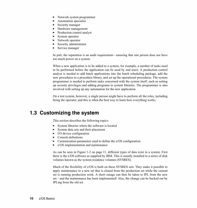
� Network system programmer� Automation specialist� Security manager� Hardware management� Production control analyst� System operator� Network operator� Security administrator� Service manager
In part, the separation is an audit requirement—ensuring that one person does not havetoo much power on a system.
When a new application is to be added to a system, for example, a number of tasks needto be performed before the application can be used by end users. A production controlanalyst is needed to add batch applications into the batch scheduling package, add thenew procedures to a procedure library, and set up the operational procedures. The systemprogrammer is needed to perform tasks concerned with the system itself, such as settingup security privileges and adding programs to system libraries. The programmer is alsoinvolved with setting up any automation for the new application.
On a test system, however, a single person might have to perform all the roles, includingbeing the operator, and this is often the best way to learn how everything works.
1.3 Customizing the systemThis section describes the following topics:� System libraries where the software is located� System data sets and their placement� I/O device configuration� Console definitions� Customization parameters used to define the z/OS configuration� z/OS implementation and maintenance
As can be seen in Figure 1-2 on page 11, different types of data exist in a system. Firstthere is the z/OS software as supplied by IBM. This is usually installed to a series of diskvolumes known as the system residence volumes (SYSRES).
Much of the flexibility of z/OS is built on these SYSRES sets. They make it possible toapply maintenance to a new set that is cloned from the production set while the currentset is running production work. A short outage can then be taken to IPL from the newset—and the maintenance has been implemented! Also, the change can be backed out byIPLing from the old set.
10 z/OS Basics

Fixes to z/OS are managed with a product called System Management Program/Extended(SMP/E). Indirect cataloging using system symbols is used so that a particular library iscataloged as being on, for example, SYSRES volume 2, and the name of that volume isresolved by the system at IPL time from the system symbols. Symbols are discussed in1.3.11, “What system symbols are” on page 19.
Figure 1-2 Types of data
Another group of volumes are the non-z/OS and non-IBM software volumes. These maybe combined into one group. The majority of non-z/OS software is not usually on theSYSRES volumes, as the SYSRES sets are usually managed as one entity by SMP/E.The other software is usually managed separately. These volumes do not form part of theSYSRES sets, and therefore there is only one copy of each library. As many volumes asrequired can be added to this group, each with an individual disk name.
Customization data refers to system libraries such as SYS1.PARMLIB,SYS1.PROCLIB, plus the master catalog, the IODF, page data sets, JES spools, and otheritems essential to the running of the system. It is also where SMP/E data is stored tomanage the software. These data sets are not always located on separate DASD volumesfrom IBM-supplied z/OS software; some installations place the PARMLIB and
z/OS software
Non-IBM software
Non-z/OS (CICS, DB2)
Customization data
User-defined exits
User data
Mainframe
Chapter 1. Overview of system programming 11
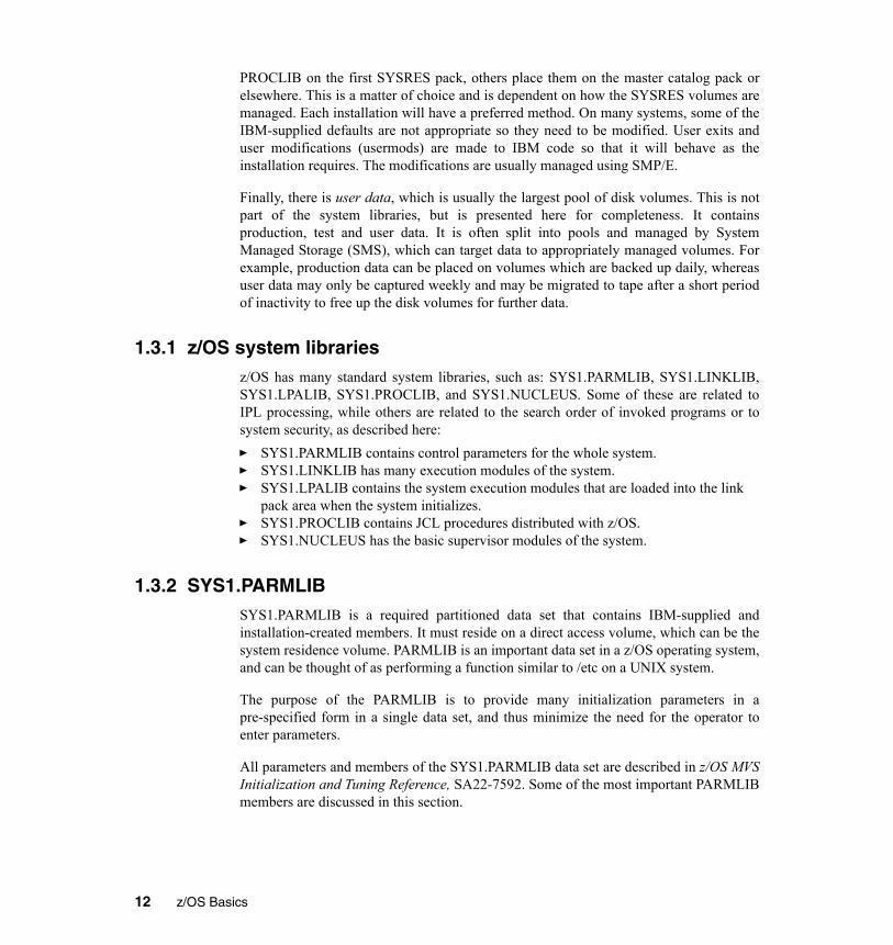
PROCLIB on the first SYSRES pack, others place them on the master catalog pack orelsewhere. This is a matter of choice and is dependent on how the SYSRES volumes aremanaged. Each installation will have a preferred method. On many systems, some of theIBM-supplied defaults are not appropriate so they need to be modified. User exits anduser modifications (usermods) are made to IBM code so that it will behave as theinstallation requires. The modifications are usually managed using SMP/E.
Finally, there is user data, which is usually the largest pool of disk volumes. This is notpart of the system libraries, but is presented here for completeness. It containsproduction, test and user data. It is often split into pools and managed by SystemManaged Storage (SMS), which can target data to appropriately managed volumes. Forexample, production data can be placed on volumes which are backed up daily, whereasuser data may only be captured weekly and may be migrated to tape after a short periodof inactivity to free up the disk volumes for further data.
1.3.1 z/OS system librariesz/OS has many standard system libraries, such as: SYS1.PARMLIB, SYS1.LINKLIB,SYS1.LPALIB, SYS1.PROCLIB, and SYS1.NUCLEUS. Some of these are related toIPL processing, while others are related to the search order of invoked programs or tosystem security, as described here:� SYS1.PARMLIB contains control parameters for the whole system. � SYS1.LINKLIB has many execution modules of the system.� SYS1.LPALIB contains the system execution modules that are loaded into the link
pack area when the system initializes.� SYS1.PROCLIB contains JCL procedures distributed with z/OS.� SYS1.NUCLEUS has the basic supervisor modules of the system.
1.3.2 SYS1.PARMLIBSYS1.PARMLIB is a required partitioned data set that contains IBM-supplied andinstallation-created members. It must reside on a direct access volume, which can be thesystem residence volume. PARMLIB is an important data set in a z/OS operating system,and can be thought of as performing a function similar to /etc on a UNIX system.
The purpose of the PARMLIB is to provide many initialization parameters in apre-specified form in a single data set, and thus minimize the need for the operator toenter parameters.
All parameters and members of the SYS1.PARMLIB data set are described in z/OS MVSInitialization and Tuning Reference, SA22-7592. Some of the most important PARMLIBmembers are discussed in this section.
12 z/OS Basics

1.3.3 Link pack area (LPA)The link pack area (LPA) is a section of the common area of an address space. It existsbelow the system queue area (SQA) and consists of the pageable link pack area (PLPA),then the fixed link pack area (FLPA), if one exists, and finally the modified link pack area(MLPA).
Link pack area (LPA) modules are loaded in common storage, shared by all addressspaces in the system. Because these modules are reentrant and are not self-modifying,each can be used by a number of tasks in any number of address spaces at the same time.Modules found in LPA do not need to be brought into virtual storage because they arealready in virtual storage.
Modules placed anywhere in the LPA are always in virtual storage, and modules placedin FLPA are also always in central storage. LPA modules must be referenced very oftenin order to prevent their pages from being stolen. When a page in LPA (other than inFLPA) is not continually referenced by multiple address spaces, it tends to be stolen.
1.3.4 Pageable link pack area (PLPA)The PLPA is an area of common storage that is loaded at IPL time (when a cold start isdone and the CLPA option is specified). This area contains read-only system programs,along with any read-only reenterable user programs selected by an installation that can beshared among users of the system. The PLPA and extended PLPA contain all members ofSYS1.LPALIB and other libraries that are specified in the active LPALSTxx through theLPA parameter in IEASYSxx or from the operator’s console at system initialization (thiswould override the PARMLIB specification).
You may use one or more LPALSTxx members in SYS1.PARMLIB to concatenate yourinstallation’s program library data sets to SYS1.LPALIB. You can also use theLPALSTxx member to add your installation’s read-only reenterable user programs to thepageable link pack area (PLPA). The system uses this concatenation, which is referred toas the LPALST concatenation, to build the PLPA during the nucleus initializing process.SYS1.LPALIB must reside in a direct access volume, which can be the system residencevolume.
Figure 1-3 shows an example of the LPALSTxx member.
Chapter 1. Overview of system programming 13
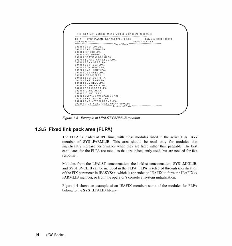
Figure 1-3 Example of LPALST PARMLIB member
1.3.5 Fixed link pack area (FLPA)The FLPA is loaded at IPL time, with those modules listed in the active IEAFIXxxmember of SYS1.PARMLIB. This area should be used only for modules thatsignificantly increase performance when they are fixed rather than pageable. The bestcandidates for the FLPA are modules that are infrequently used, but are needed for fastresponse.
Modules from the LPALST concatenation, the linklist concatenation, SYS1.MIGLIB,and SYS1.SVCLIB can be included in the FLPA. FLPA is selected through specificationof the FIX parameter in IEASYSxx, which is appended to IEAFIX to form the IEAFIXxxPARMLIB member, or from the operator’s console at system initialization.
Figure 1-4 shows an example of an IEAFIX member; some of the modules for FLPAbelong to the SYS1.LPALIB library.
F ile E d it E d it_ S e tt in g s M e n u U t ili t ie s C o m p ile rs Te s t H e lp - - - - - - - - - - - - - - - - - - - - - - - - - - - - - - - - - - - - - - - - - - - - - - - - - - - - - - - - - - - - - - - - - - - - - - - - - - - - - - -E D IT S Y S 1 .P A R M L IB (L P A L S T 7 B ) - 0 1 .0 3 C o lu m n s 0 0 0 0 1 0 0 0 7 2 C o m m a n d = = = > S c ro ll = = = > C S R * * * * * * * * * * * * * * * * * * * * * * * * * * * * * * * * * * * To p o f D a ta * * * * * * * * * * * * * * * * * * * * * * * * * * * * * *0 0 0 2 0 0 S Y S 1 .L P A L IB , 0 0 0 2 2 0 S Y S 1 .S E R B L P A , 0 0 0 3 0 0 IS F.S IS F L P A , 0 0 0 5 0 0 IN G .S IN G M O D 3 , 0 0 0 6 0 0 N E T V IE W .S C N M L P A 1 , 0 0 0 7 0 0 S D F 2 .V 1 R 4 M 0 .S D G IL P A , 0 0 0 8 0 0 R E X X .S E A G L P A , 0 0 1 0 0 0 S Y S 1 .S IA T L P A , 0 0 1 1 0 0 E O Y .S E O Y L P A , 0 0 1 2 0 0 S Y S 1 .S B D T L P A , 0 0 1 3 0 0 C E E .S C E E L P A , 0 0 1 4 0 0 IS P .S IS P L P A , 0 0 1 6 0 0 S Y S 1 .S O R T L P A , 0 0 1 7 0 0 S Y S 1 .S IC E L P A , 0 0 1 8 0 0 E U V .S E U V L P A , 0 0 1 9 0 0 T C P IP .S E Z A L P A , 0 0 2 0 0 0 E Q A W .S E Q A L P A , 0 0 2 0 0 1 ID I.S ID IA L P A , 0 0 2 0 0 2 ID I.S ID IL P A 1 , 0 0 2 0 0 3 D W W .S D W W L P A (S B O X 2 0 ) , 0 0 2 0 1 0 S Y S 1 .S D W W D L P A , 0 0 2 0 2 0 D V G .N F T P 2 3 0 .S D V G L P A , 0 0 2 2 0 0 C IC S T S 2 2 .C IC S .S D F H L P A (S B O X D 3 ) * * * * * * * * * * * * * * * * * * * * * * * * * * * * * * * * * * B o t to m o f D a ta * * * * * * * * * * * * * * * * * * * * * * * * * * * *
14 z/OS Basics

Figure 1-4 Example of an IEAFIX PARMLIB member
1.3.6 Modified link pack area (MLPA)The MLPA can be used to contain reenterable routines from APF-authorized librariesthat are to be part of the pageable extension to the link pack area during the current IPL.Note that the MLPA exists only for the duration of an IPL. Therefore, if an MLPA isdesired, the modules in the MLPA must be specified for each IPL (including quick startand warm start IPLs). When the system searches for a routine, the MLPA is searchedbefore the PLPA. The MLPA can be used at IPL time to temporarily modify or update thePLPA with new or replacement modules.
1.3.7 SYS1.PROCLIBSYS1.PROCLIB is a required partitioned data set that contains the JCL procedures usedto perform certain system functions. The JCL can be for system tasks or processingprogram tasks invoked by the operator or the programmer.
1.3.8 The master scheduler subsystemThe master scheduler subsystem is used to establish communication between theoperating system and the primary job entry subsystem, which can be JES2 or JES3.
File Edit Edit_Settings Menu Utilities Compilers Test Help -------------------------------------------------------------------------------EDIT SYS1.PARMLIB(IEAFIX00) - 01.00 Columns 00001 00072 Command ===> Scroll ===> CSR ****** ***************************** Top of Data ******************************000001 INCLUDE LIBRARY(SYS1.LPALIB) MODULES( 000002 IEAVAR00 000003 IEAVAR06 000004 IGC0001G 000005 ) 000006 INCLUDE LIBRARY(FFST.V120ESA.SEPWMOD2) MODULES( 000007 EPWSTUB 000008 ) ****** **************************** Bottom of Data ****************************
Chapter 1. Overview of system programming 15

When you start z/OS, master initialization routines initialize system services, such as thesystem log and communication task, and start the master scheduler address space, whichbecomes address space number one (ASID=1).
Then, the master scheduler may start the job entry subsystem (JES2 or JES3). JES is theprimary job entry subsystem. On many production systems JES is not startedimmediately; instead, the automation package starts all tasks in a controlled sequence.Then other defined subsystems are started. All subsystems are defined in the IEFSSNxxmember of PARMLIB. These subsystems are secondary subsystems.
An initial MSTJCL00 load module can be found in SYS1.LINKLIB library. Ifmodifications are required, the recommended procedure is to create a MSTJCLxxmember in PARMLIB. The suffix is specified by the MSTRJCL parameter in theIEASYSxx member of PARMLIB. The MSTJCLxx member is commonly called masterJCL. It contains data definition (DD) statements for all system input and output data setsthat are needed to do the communication between the operating system and JES.
Example 1-1 shows an example of an MSTJCLxx member.
File Edit Edit_Settings Menu Utilities Compilers Test Help -------------------------------------------------------------------------------EDIT SYS1.PARMLIB(MSTJCL00) - 01.07 Columns 00001 00072 Command ===> Scroll ===> CSR ****** ***************************** Top of Data ******************************000100 //MSTRJCL JOB MSGLEVEL=(1,1),TIME=1440 000200 // EXEC PGM=IEEMB860,DPRTY=(15,15) 000300 //STCINRDR DD SYSOUT=(A,INTRDR) 000400 //TSOINRDR DD SYSOUT=(A,INTRDR) 000500 //IEFPDSI DD DSN=SYS1.PROCLIB,DISP=SHR 000600 // DD DSN=CPAC.PROCLIB,DISP=SHR 000700 // DD DSN=SYS1.IBM.PROCLIB,DISP=SHR 000800 //IEFJOBS DD DSN=SYS1.STCJOBS,DISP=SHR 000900 //SYSUADS DD DSN=SYS1.UADS,DISP=SHR ****** **************************** Bottom of Data ****************************
Example 1-1 Sample master JCL
When the master scheduler has to process the start of a started task, the systemdetermines whether the START command refers to a procedure or to a job. If theIEFJOBS DD exists in the MSTJCLxx member, the system searches the IEFJOBS DDconcatenation for the member requested in the START command.
If there is no member by that name in the IEFJOBS concatenation, or if the IEFJOBSconcatenation does not exist, the system searches the IEFPDSI DD for the memberrequested in the START command. If a member is found, the system examines the firstrecord for a valid JOB statement and, if one exists, uses the member as the JCL sourcefor the started task. If the member does not have a valid JOB statement in its first record,
16 z/OS Basics

the system assumes that the source JCL is a procedure and creates JCL to invoke theprocedure.
After the JCL source has been created (or found), the system processes the JCL. Asshipped, MSTJCL00 contains an IEFPDSI DD statement that defines the data set thatcontains procedure source JCL for started tasks. Normally this data set isSYS1.PROCLIB; it may be a concatenation. For useful work to be performed,SYS1.PROCLIB must at least contain the procedure for the primary JES, as shown innext section.
1.3.9 A job procedure librarySYS1.PROCLIB contains the JES2 cataloged procedure. This procedure defines thejob-related procedure libraries, as shown in Example 1-2.
Example 1-2 How to specify procedure libraries in the JES2 procedure
//PROC00 DD DSN=SYS1.PROCLIB,DISP=SHR// DD DSN=SYS3.PROD.PROCLIB,DISP=SHR//PROC01 DD DSN=SYS1.PROC2,DISP=SHR...//PROC99 DD DSN=SYS1.LASTPROC,DISP=SHR...
Many installations have very long lists of procedure libraries in the JES procedure. Thisis because JCLLIB is a relatively recent innovation.
Care should be taken as to the number of users who can delete these libraries becauseJES will not start if one is missing. Normally a library that is in use cannot be deleted, butJES does not hold these libraries although it uses them all the time.
You can override the default specification by specifying this statement:/*JOBPARM PROCLIB=
After the name of the procedure library, you code the name of the DD statement in theJES2 procedure that points to the library to be used. For example, in Figure 1-2, let’sassume that you run a job in class A and that class has a default proclib specification onPROC00. If you want to use a procedure that resides in SYS1.LASTPROC, you’ll needto include this statement in the JCL:/*JOBPARM PROCLIB=PROC99
Another way to specify a procedure library is to use the JCLLIB JCL statement. Thisstatement allows you to code and use procedures without using system procedurelibraries. The system searches the libraries in the order in which you specify them on theJCLLIB statement, prior to searching any unspecified default system procedure libraries.
Chapter 1. Overview of system programming 17
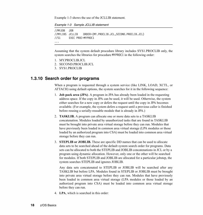
Example 1-3 shows the use of the JCLLIB statement.
Example 1-3 Sample JCLLIB statement
//MYJOB JOB//MYLIBS JCLLIB ORDER=(MY.PROCLIB.JCL,SECOND.PROCLIB.JCL)//S1 EXEC PROC=MYPROC1...
Assuming that the system default procedure library includes SYS1.PROCLIB only, thesystem searches the libraries for procedure MYPROC1 in the following order:1. MY.PROCLIB.JCL2. SECOND.PROCLIB.JCL3. SYS1.PROCLIB
1.3.10 Search order for programsWhen a program is requested through a system service (like LINK, LOAD, XCTL, orATTACH) using default options, the system searches for it in the following sequence:
1. Job pack area (JPA). A program in JPA has already been loaded in the requesting address space. If the copy in JPA can be used, it will be used. Otherwise, the system either searches for a new copy or defers the request until the copy in JPA becomes available. (For example, the system defers a request until a previous caller is finished before reusing a serially-reusable module that is already in JPA.)
2. TASKLIB. A program can allocate one or more data sets to a TASKLIB concatenation. Modules loaded by unauthorized tasks that are found in TASKLIB must be brought into private area virtual storage before they can run. Modules that have previously been loaded in common area virtual storage (LPA modules or those loaded by an authorized program into CSA) must be loaded into common area virtual storage before they can run.
3. STEPLIB or JOBLIB. These are specific DD names that can be used to allocate data sets to be searched ahead of the default system search order for programs. Data sets can be allocated to both the STEPLIB and JOBLIB concatenations in JCL or by a program using dynamic allocation. However, only one or the other will be searched for modules. If both STEPLIB and JOBLIB are allocated for a particular jobstep, the system searches STEPLIB and ignores JOBLIB.
Any data sets concatenated to STEPLIB or JOBLIB will be searched after anyTASKLIB but before LPA. Modules found in STEPLIB or JOBLIB must be broughtinto private area virtual storage before they can run. Modules that have previouslybeen loaded in common area virtual storage (LPA modules or those loaded by anauthorized program into CSA) must be loaded into common area virtual storagebefore they can run.
4. LPA, which is searched in this order:
18 z/OS Basics

a. Dynamic LPA modules, as specified in PROGxx members b. Fixed LPA (FLPA) modules, as specified in IEAFIXxx members c. Modified LPA (MLPA) modules, as specified in IEALPAxx members d. Pageable LPA (PLPA) modules, loaded from libraries specified in LPALSTxx or
PROGxx
LPA modules are loaded in common storage, shared by all address spaces in thesystem. Because these modules are reentrant and are not self-modifying, each can beused by any number of tasks in any number of address spaces at the same time.Modules found in LPA do not need to be brought into virtual storage, because theyare already in virtual storage.
5. Libraries in the linklist, as specified in PROGxx and LNKLSTxx. By default, the linklist begins with SYS1.LINKLIB, SYS1.MIGLIB, and SYS1.CSSLIB. However, you can change this order using SYSLIB in PROGxx and add other libraries to the linklist concatenation. The system must bring modules found in the linklist into private area virtual storage before the programs can run.
The default search order can be changed by specifying certain options on the macros usedto call programs. The parameters that affect the search order the system will use are EP,EPLOC, DE, DCB, and TASKLIB.
Related Reading: For more information about these parameters, see the topic on loadmodule search in the IBM publication z/OS MVS Programming: Assembler ServicesGuide. Some IBM subsystems (notably CICS and IMS) and applications (such as ISPF)use these facilities to establish search orders for other programs.
1.3.11 What system symbols areSystem symbols are elements that allow different z/OS systems to share PARMLIBdefinitions while retaining unique values in those definitions. System symbols act likevariables in a program; they can take on different values, based on the input to theprogram. When you specify a system symbol in a shared PARMLIB definition, thesystem symbol acts as a “placeholder”. Each system that shares the definition replacesthe system symbol with a unique value during initialization.
Each system symbol has a name (which begins with an ampersand (&) and optionallyends with a period (.)) and a substitution text, which is the character string that the systemsubstitutes for a symbol each time it appears.
There are two types of system symbols:
dynamic The substitution text can change at any point in an IPL.
static The substitution text is defined at system initialization and remains fixed for the life of an IPL.
Chapter 1. Overview of system programming 19

There are symbols that are reserved for system use. You can display the symbols in yoursystem by entering the D SYMBOLS command. Example 1-4 shows the result of enteringthis command.
Example 1-4 Partial output of the D SYMBOLS command (some lines removed)
HQX7708 ----------------- SDSF PRIMARY OPTION MENU -- COMMAND INPUT ===> -D SYMBOLS IEA007I STATIC SYSTEM SYMBOL VALUES &SYSALVL. = "2" &SYSCLONE. = "70" &SYSNAME. = "SC70" &SYSPLEX. = "SANDBOX" &SYSR1. = "Z17RC1" &ALLCLST1. = "CANCEL" &CMDLIST1. = "70,00" &COMMDSN1. = "COMMON" &DB2. = "V8" &DCEPROC1. = "." &DFHSMCMD. = "00" &DFHSMHST. = "6" &DFHSMPRI. = "NO" &DFSPROC1. = "." &DLIB1. = "Z17DL1" &DLIB2. = "Z17DL2" &DLIB3. = "Z17DL3" &DLIB4. = "Z17DL4" &IEFSSNXX. = "R7" &IFAPRDXX. = "4A"
The IEASYMxx member of PARMLIB provides a single place to specify systemparameters for each system in a multisystem environment. IEASYMxx containsstatements that define static system symbols and specify IEASYSxx members thatcontain system parameters (the SYSPARM statement).
Example 1-5 shows a portion of a typical IEASYMxx member
Example 1-5 Partial IEASYMxx PARMLIB member (some lines removed)
SYSDEF SYSCLONE(&SYSNAME(3:2)) SYMDEF(&SYSR2='&SYSR1(1:5).2') SYMDEF(&SYSR3='&SYSR1(1:5).3') SYMDEF(&DLIB1='&SYSR1(1:3).DL1') SYMDEF(&DLIB2='&SYSR1(1:3).DL2') SYMDEF(&DLIB3='&SYSR1(1:3).DL3') SYMDEF(&DLIB4='&SYSR1(1:3).DL4') SYMDEF(&ALLCLST1='CANCEL') SYMDEF(&CMDLIST1='&SYSCLONE.,00')
20 z/OS Basics

SYMDEF(&COMMDSN1='COMMON') SYMDEF(&DFHSMCMD='00') SYMDEF(&IFAPRDXX='00') SYMDEF(&DCEPROC1='.') SYMDEF(&DFSPROC1='.') SYSDEF HWNAME(SCZP901) LPARNAME(A13) SYSNAME(SC70) SYSPARM(R3,70) SYMDEF(&IFAPRDXX='4A') SYMDEF(&DFHSMHST='6') SYMDEF(&DFHSMPRI='NO') SYMDEF(&DB2='V8')
In the example, the variable &SYSNAME will have the value specified by theSYSNAME keyword - SC70 in this case. Because each system in a sysplex has a uniquename, we can use &SYSNAME in the specification of system-unique resources, wherepermitted. As an example, we could specify the name of an SMF data set asSYS1.&SYSNAME..MAN1, with substitution resulting in the name SYS1.SC70.MAN1when running on SC70.
You can use variables to construct the values of other variables. In Figure 1-5, we see&SYSCLONE taking on the value of &SYSNAME beginning at position 3 for a lengthof 2. Here, &SYSCLONE will have a value of 70. Similarly, we see &SYSR2constructed from the first 5 positions of &SYSR1 with a suffix of 2. Where is &SYSR1defined? &SYSR1 is system-defined with the VOLSER of the IPL volume. If you referback to Figure 1-4 on page 20, you will see the values of &SYSR1 and &SYSR2.
We also see here the definition of a global variable defined to all systems - &IFAPRDXXwith a value of 00 - and its redefinition for SC70 to a value of 4A.
System symbols are used in cases where multiple z/OS systems will share a singlePARMLIB. Here, the use of symbols allows individual members to be used withsymbolic substitution, as opposed to having each system require a unique member. TheLOADxx member specifies the IEASYMxx member that the system is to use.
1.4 Managing system performanceThe task of “tuning” a system is an iterative and continuous process, and it is thediscipline that most directly impacts all users of system resources in an enterprise. Thez/OS Workload Management (WLM) component is an important part of this process andincludes initial tuning of selecting appropriate parameters for various system componentsand subsystems.
Chapter 1. Overview of system programming 21

After the system is operational and criteria have been established for the selection of jobsfor execution through job classes and priorities, WLM controls the distribution ofavailable resources according to the parameters specified by the installation.
WLM, however, can only deal with available resources. If these are inadequate to meetthe needs of the installation, even optimal distribution may not be the answer; other areasof the system should be examined to determine the possibility of increasing availableresources. When requirements for the system increase and it becomes necessary to shiftpriorities or acquire additional resources (such as a larger processor, more storage, ormore terminals), the system programmer needs to modify WLM parameters to reflectchanged conditions.
1.5 Configuring I/O devicesThe I/O configuration to the operating system (software) and the channel subsystem(hardware) must be defined. The Hardware Configuration Definition (HCD) componentof z/OS consolidates the hardware and software I/O configuration processes under asingle interactive end-user interface (a large set of ISPF panels).
HCD is used for several purposes:� Using input from the ISPF panels, it builds a special VSAM data set that defines the
I/O configuration available to z/OS. The data set is known as an I/O definition file (IODF), which contains I/O configuration data. An IODF is used to define multiple hardware and software configurations to the z/OS operating system. When z/OS is started, an IODF must be specified. Every I/O device used by z/OS must be defined in the IODF.
� HCD builds an I/O definition for the complete mainframe machine and sends it to the controller section of the mainframe. This definition also specifies the existence of LPARs and other system-wide parameters. This is known as an I/O Configuration Data Set (IOCDS). The IOCDS is discussed in more detail in Chapter 3, “Hardware systems and LPARs” on page 77.
� HCD can be used to create a new IODF from an existing IODF and dynamically activate the new version.
When a new IODF is activated, HCD defines the I/O configuration to the channelsubsystem and/or the operating system. With the HCD activate function or the z/OSACTIVATE operator command, changes can be made in the current configurationwithout having to initial program load (IPL) the software or power-on reset (POR) thehardware. Making changes while the system is running is known as dynamicconfiguration or dynamic reconfiguration.
An IODF and IOCDS can contain definitions for I/O devices that do not exist or are notcurrently attached. It need not contain definitions for all I/O devices, although the system
22 z/OS Basics

(for the IOCDS) or z/OS (for an IODF) cannot use a device that is not defined. HCD isincluded with all z/OS systems.
1.6 Following a process of change controlData center management is typically held accountable for Service Level Agreements(SLAs), often through a specialist team of service managers. Change control mechanicsand practices in a data center are implemented to ensure that SLAs are met.
The implementation of any change must be under the control of the Operations staff.When a change is introduced into a production environment that results in problems orinstability, Operations staff are responsible for observing, reporting, and then managingthe activities required to correct the problem or back out the change.
Although system programmers will normally raise and implement their own changes,sometimes changes are based on a request through the change management system. Anyinstructions for Operations or other groups would be in the change record, and theapproval of each group is required.
Implementing business application changes would normally be handled by a productioncontrol analyst. Application changes will normally reside in test libraries, and an officialrequest (with audit trail) would result in the programs in the test libraries being promotedto the production environment.
Procedures involved in the change must be circulated to all interested parties. When allparties consider the change description to be complete, then it is considered forimplementation and either scheduled, deferred, or possibly rejected.
The factors that need to be considered when planning a change are:� The benefits that will result from the change� What will happen if the change is not done� The resources required to implement the change� The relative importance of the change request compared to others� Any interdependency of change requests
All change involves risk. One of the advantages of the mainframe is the very highavailability that it offers. All change must therefore be carefully controlled and managed.A high proportion of any system programmer’s time is involved in the planning and riskassessment of change. One of the most important aspects of change is how to reverse itand go back to the previous state.
Chapter 1. Overview of system programming 23

1.6.1 Risk assessmentIt is common practice for data center management to have a weekly change controlmeeting to discuss, approve, or reject changes. These changes might be for applications,a system, a network, hardware, or power.
An important part of any change is risk assessment, in which the change is consideredand evaluated from the point of view of risk to the system. Low risk changes may bepermitted during the day, while higher risk changes would be scheduled for an outageslot.
It is also common practice for a data center to have periods of low and high risk, whichwill influence decisions. For example, if the system runs credit authorizations, then theperiods around major public holidays are usually extremely busy and may cause a changefreeze. Also, annual sales are extremely busy periods in retailing and may cause changesto be rejected.
IT organizations achieve their goals through disciplined change management processesand policy enforcement. These goals include:� High service availability� Increased security� Audit readiness� Cost savings
1.6.2 Change control record systemA change control record system is typically in place to allow for the requesting, tracking,and approval of changes. This is usually the partner of a problem management system.For example, if a production system has a serious problem on a Monday morning, thenone of the first actions will be to examine the changes that were implemented over theweekend to determine if these have any bearing on the problem.
These records also show that the system is under control, which is often necessary toprove to auditors, especially in the heavily regulated financial services sector. TheSarbanes-Oxley Act of 2002 in the United States, which addresses corporate governance,has established the need for an effective internal control system. Demonstrating strongchange management and problem management in IT services is part of compliance withthis measure. Additionally, the 8th Directive on Company Law in the European Union,which is under discussion at the time of writing, will address similar areas toSarbanes-Oxley.
For these reasons, and at a bare minimum, before any change is implemented thereshould be a set of controlled documents defined, which are known as change requestforms. These should include the following:
24 z/OS Basics

� Who - that is, the department, group or person that requires the change, who is responsible for implementing the change, completing the successful test and responsible for backout if required. Also who will “sign off” the change as successful.
� What - that is, the affected systems or services (for example e-mail, file service, domain, etc.). Include as much detail as possible. Ideally, complete instructions should be included so that the change could be performed by someone else in an emergency.
� Where - that is, scope of change, the business units, buildings, departments or groups affected or required to assist with the change.
� When - that is, start date and time and estimated duration of the change. There are often three dates: requested, scheduled. and actual.
� Priority - that is, high, medium, low, business as usual, emergency, dated (for example clock change).
� Risk - that is, high, medium, low� Impact - that is, what will happen if the change is implemented; what will happen if it
is not; what other systems may be affected; what will happen if something unexpected occurs.
1.6.3 Production controlProduction control usually involves a specialized staff to manage batch scheduling, usinga tool such as Tivoli® Workload Scheduler to build and manage a complex batchschedule. This work might involve daily and weekly backups running at particular pointswithin a complex sequence of application suites. Databases and online services mightalso be taken down and brought back up as part of the schedule. While making suchchanges, production control often needs to accommodate public holidays and otherspecial events such as (in the case of a retail sales business) a winter sale.
Production control is also responsible for taking a programmer’s latest program andreleasing it to production. This task typically involves moving the source code to a secureproduction library, recompiling the code to produce a production load module, andplacing that module in a production load library. JCL is copied and updated to productionstandards and placed in appropriate procedure libraries, and application suites added tothe job scheduler.
There might also be an interaction with the system programmer if a new library needs tobe added to the linklist, or authorized.
Chapter 1. Overview of system programming 25

1.7 Configuring consolesOperating z/OS involves managing hardware such as processors and peripheral devices(including the consoles where your operators do their work); and software such as thez/OS operating control system, the job entry subsystem, subsystems (such as NetView®)that can control automated operations, and all the applications that run on z/OS.
The operation of a z/OS system involves the following:� Message and command processing that forms the basis of operator interaction with
z/OS and the basis of z/OS automation� Console operations, or how operators interact with z/OS to monitor or control the
hardware and software
Planning z/OS operations for a system must take into account how operators use consolesto do their work and how to manage messages and commands. The system programmerneeds to ensure that operators receive the necessary messages at their consoles to performtheir tasks, and select the proper messages for suppression, automation, or other kinds ofmessage processing.
In terms of z/OS operations, how the installation establishes console recovery or whetheran operator must re-IPL a system to change processing options are important planningconsiderations.
Because messages are also the basis for automated operations, the system programmerneeds to understand message processing to plan z/OS automation.
As more installations make use of multisystem environments, the need to coordinate theoperating activities of those systems becomes crucial. Even for single z/OS systems, aninstallation needs to think about controlling communication between functional areas(such as a tape-pool library and the master console area, for example). In both single andmultisystem environments, the commands that operators can enter from consoles can bea security concern that requires careful coordination. As a planner, the systemprogrammer needs to make sure that the right people are doing the right tasks when theyinteract with z/OS.
A console configuration consists of the various consoles that operators use tocommunicate with z/OS. Your installation first defines the I/O devices it can use asconsoles through the Hardware Configuration Definition (HCD), an interactive interfaceon the host that allows the system programmer to define the hardware configuration forboth the channel subsystem and operating system.
Hardware Configuration Manager (HCM) is the graphical user interface to HCD. HCMinteracts with HCD in a client/server relationship (that is, HCM runs on a workstationand HCD runs on the host). The host systems require an internal model of theirconnections to devices, but it can be more convenient and efficient for the system
26 z/OS Basics

programmer to maintain (and supplement) that model in a visual form. HCM maintainsthe configuration data as a diagram in a file on the workstation in sync with the IODF onthe host. While it is possible to use HCD directly for hardware configuration tasks, manycustomers prefer to use HCM exclusively, due to its graphical interface.
Besides HCD, once the devices have been defined, z/OS is told which devices to use asconsoles by specifying the appropriate device numbers in the CONSOLxx PARMLIBmember.
Generally, operators on a z/OS system receive messages and enter commands on MCSand SMCS consoles. They can use other consoles (such as NetView consoles) to interactwith z/OS, but here we describe MCS, SMCS, and EMCS consoles and how to plan fortheir use: � MCS consoles are devices that are locally attached to a z/OS system and provide the
basic communication between operators and z/OS. (MCS consoles are attached to control devices that do not support systems network architecture (SNA) protocols.)
� SMCS consoles are devices that do not have to be locally attached to a z/OS system and provide the basic communication between operators and z/OS. SMCS consoles use z/OS Communications Server to provide communication between operators and z/OS, instead of direct I/O to the console device.
� EMCS consoles are devices (other than MCS or SMCS consoles) from which operators or programs can enter commands and receive messages. Defining extended MCS consoles as part of the console configuration allows the system programmer to extend the number of consoles beyond the MCS console limit, which is 99 for an z/OS system or sysplex.
The system programmer defines these consoles in a configuration according to theirfunctions. For example, one console can function as a master console for the system.Important messages that require action can be directed to the operator, who can act byentering commands on the console. Another console can act as a monitor to displaymessages to an operator working in a functional area like a tape pool library, or to displaymessages about printers at your installation.
Figure 1-5 shows a console configuration for a z/OS system that also includes the systemconsole, an SMCS console, NetView, and TSO/E.
Chapter 1. Overview of system programming 27

Figure 1-5 Sample console configuration for a z/OS system
The system console function is provided as part of the Hardware Management Console(HMC). An operator can use the system console to initialize z/OS and other systemsoftware, and during recovery situations when other consoles are unavailable.
Besides MCS and SMCS consoles, the z/OS system shown in Figure 1-5 has a NetViewconsole defined to it. NetView works with system messages and command lists to helpautomate z/OS operator tasks. Many system operations can be controlled from a NetViewconsole.
Users can monitor many z/OS system functions from TSO/E terminals. Using the SystemDisplay and Search Facility (SDSF) and the Resource Measurement Facility (RMF™),TSO/E users can monitor z/OS and respond to workload balancing and performanceproblems. An authorized TSO/E user can also initiate an extended MCS console sessionto interact with z/OS.
System console (attached to the processor controller)
MCS Master console
MCS status display console
MCS message stream console
SMCS console
TSO/E session with
SDSF
TSO/E session with RMF
Extended MCS console with master authority
NetView console
VTAM(SMCS) TSO/E
NETVIEW
z/OS operating system
28 z/OS Basics

The MCS consoles shown in Figure 1-5 are: � An MCS master console from which an operator can view messages and enter all
z/OS commands
This console is in full capability mode because it can receive messages and acceptcommands. An operator can control the operations for the z/OS system from an MCSor SMCS master console.
� An MCS status display console
An operator can view system status information from DEVSERV, DISPLAY,TRACK, or CONFIG commands. However, because this is a status display console,an operator cannot enter commands from the console. An operator on a full capabilityconsole can enter these commands and route the output to a status display console forviewing.Note: an SMCS console cannot be a status display console.
� An MCS message-stream console
A message-stream console can display system messages. An operator can viewmessages routed to this console. However, because this is a message-stream console,an operator cannot enter commands from here. Routing codes and message levelinformation for the console are defined so that the system can direct relevantmessages to the console screen for display. Thus, an operator who is responsible for afunctional area like a tape pool library, for example, can view MOUNT messages. AnSMCS console cannot be a message stream console.
In many installations, this proliferation of screens has been replaced by operatorworkstations that combine many of these screens onto one windowed display. Generally,the hardware console is separate, but most other terminals are combined. The systems aremanaged by alerts for exception conditions from the automation product.
The IBM Open Systems Adapter-Express Integrated Console Controller (OSA-ICC) isthe modern way of connecting consoles. OSA-ICC uses TCP/IP connections overEthernet LAN to attach to personal computers as consoles through a TN3270 connection(telnet).
1.8 Using SMP/E to manage changesSystem Management Program/Extended (SMP/E) is the program used by the systemprogrammers to install software products, updates, and fixes on z/OS. Using SMP/E isone of the most complex functions associated with maintaining z/OS software.Figure 0-1 illustrates the general flow when using SMP/E to apply a fix to z/OS. Suchfixes for z/OS software are known as PTFs, for Product Temporary Fix.
Chapter 1. Overview of system programming 29

Figure 0-1 SMP/E overview for fixes
SMP/E works with three levels of libraries:
� A receive-level library that is a holding area - This library is known as the PTS (PTF Temporary Storage) and is in the GLOBAL zone.
� Operational or target libraries - These are the working libraries used by z/OS and various software products while they are installed for use.
� Distribution libraries or DLIBs - These contain a master copy of all the modules in the operational libraries. The DLIBs are not used for execution.
Each set of libraries has a Consolidated Software Index (CSI), which is a VSAM data setcontaining data about all the modules in the set. In principle, it is possible to rebuild anyoperational z/OS module from the DLIBs. The CSI contains all the binder (linkageeditor) control statements needed to rebuild an operational module from submodules inthe DLIBs.
The SMP/E RECEIVE command is used to accept modules (or submodules of a largermodule) that are fixes for distributed products. The RECEIVEed module is placed in thePTS. The APPLY CHECK command is used to determine whether the fix can be cleanlyapplied to the operational module. (This may involve relinking/rebinding manysubmodules.) If these checks are positive, the APPLY command is used to install the fixin the operational libraries. The installation would then use the fixed module anddetermine whether it is acceptable. If it is not acceptable, a RESTORE command canrebuild the original module from material in the DLIBs.
RECEIVE
GLOBALLIBRARY
APPLY [CHECK]
OPERATIONALLIBRARIES
DISTRIBUTIONLIBRARIES
ACCEPT
RESTORE
PTS CSI
LibsLibs
LibsLibs
LibsLibs
DELETE
CSI
REJECT
CSI
LibsLibs
LibsLibs
LibsLibs
30 z/OS Basics

If the fix is acceptable (and it make take months to determine this) an ACCEPTcommand integrates the fix module into the DLIBs. After this is done, the fix can nolonger be backed out of the system (except by restoring old backup tapes, perhaps).Future fixes can then be built on top of this fix in the DLIBs. A REJECT command isused to discard a fix from the global area; this might be done if someone decides the fixwill never be used.
SMP/E control statements can verify the status of previous and concurrent fixes, theexistence of a product and its release level, and many other factors.
z/OS and practically all z/OS software products from IBM are installed using SMP/E.Most independent software vendor products are installed by using SMP/E. Many z/OSinstallations will not purchase any software that is not installed with SMP/E.
Each product can have its own global, target, and DLIB libraries, or many products canbe placed in the same set of global, target, and DLIB libraries. SMP/E is included with allz/OS systems.
SMP/E usage can be quite complex and SMP/E skills are a primary prerequisite for az/OS system programmer. The DLIBs for a product (including z/OS) tend to be as largeas the operational libraries. In a sense, almost all the software for z/OS and mostassociated software products are present twice on disk, once for the operational librariesand once for the distribution libraries.
In earlier days, when disks were smaller and more expensive, some installations did notkeep their DLIBs online. In principle, they are needed only when a fix or new product isinstalled and they could occupy a number of disk drives. Smaller installations mightdump the DLIB volumes onto tape and restore them (to scratch disks) only when needed.In even earlier days the use of SMP/E was considered optional and some installations didnot maintain their DLIBs. In today’s systems, however, the DLIBs are required for mostpractical purposes and are usually available online.
1.9 Initializing the systemAn initial program load (IPL) is the act of loading a copy of the operating system fromdisk into the processor’s real storage and executing it.
z/OS systems are designed to run continuously with many months between reloads,allowing important production workloads to be continuously available. Change is theusual reason for a reload, and the level of change on a system dictates the reloadschedule. For example:� A test system may be IPLed daily or even more often.� A high-availability banking system may only be reloaded once a year, or even less
frequently, to refresh the software levels.
Chapter 1. Overview of system programming 31

� Outside influences may often be the cause of IPLs, such as the need to test and maintain the power systems in the machine room.
� Sometimes badly behaved software uses up system resources that can only be replenished by an IPL, but this sort of behavior is normally the subject of investigation and correction.
Many of the changes that required an IPL in the past can now be done dynamically.Examples of these tasks are:� Changing the content of linklist, the APF list or the IO configuration� Adding modules to LPA
z/OS is IPLed using the Hardware Management Console (HMC). You need to supply thefollowing information to IPL z/OS:� Device address of the IPL volume� Suffix of the LOADxx member, which contains pointers to system parameters and the
IODF data set, which contains the configuration information.� Device address of the IODF volume, which is the starting point for the system search
for the SYSn.IPLPARM data set that contains the LOADxx member.� Message suppression character � Optional nucleus suffix
1.9.1 Initialization processThe system initialization process (Figure 1-6 on page 33) prepares the system controlprogram and its environment to do work for the installation. This process essentiallyconsists of: � System and storage initialization, including the creation of system component address
spaces� Master scheduler initialization and subsystem initialization
When the system is initialized and the job entry subsystem is active, the installation cansubmit jobs for processing by using the START, LOGON, or MOUNT command.
The initialization process begins when the system programmer selects the LOADfunction at the Hardware Management Console (HMC). z/OS locates all usable centralstorage that is online and available, and begins creating the various system areas.
32 z/OS Basics

Figure 1-6 IPLing the machine
Not all disks attached to a CPU have loadable code on them. A disk that does is generallyreferred to as an “IPLable” disk, and more specifically as the SYSRES volume.
IPLable disks contain a bootstrap module at cylinder 0 track 0. At IPL, this bootstrap isloaded into storage at real address zero and control is passed to it. The bootstrap thenreads the IPL control program IEAIPL00 (also known as IPL text) and passes control toit. This in turn starts the more complex task of loading the operating system andexecuting it.
After the bootstrap is loaded and control is passed to IEAIPL00, IEAIPL00 prepares anenvironment suitable for starting the programs and modules that make up the operatingsystem, as follows:
1. It clears central storage to zeros before defining storage areas for the master scheduler.
2. It locates the SYS1.NUCLEUS data set on the SYSRES volume and loads a series of programs from it known as IPL Resource Initialization Modules (IRIMs).
3. These IRIMs begin creating the normal operating system environment of control blocks and subsystems.
LOADPARM
IPL
bootstrapIPL ccuu
SYSRES
IPLtext
IODF ccuu LOADxx IMSI AltNuc
1 - 4 5 - 6 7 8
Chapter 1. Overview of system programming 33

Some of the more significant tasks performed by the IRIMs are as follows:� Read the LOADPARM information entered on the hardware console at the time the
IPL command was executed.� Search the volume specified in the LOADPARM member for the IODF data set.
IRIM will first attempt to locate LOADxx in SYS0.IPLPARM. If this is unsuccessful, it will look for SYS1.IPLPARM, and so on, up to and including SYS9.IPLPARM. If at this point it still has not been located, the search continues in SYS1.PARMLIB. (If LOADxx cannot be located, the system loads a wait state.)
� If a LOADxx member is found, it is opened and information including the nucleus suffix (unless overridden in LOADPARM), the master catalog name, and the suffix of the IEASYSxx member to be used, is read from it.
� Load the operating system’s nucleus.� Initialize virtual storage in the master scheduler address space for the System Queue
Area (SQA), the Extended SQA (ESQA), the Local SQA (LSQA), and the Prefixed Save Area (PSA). At the end of the IPL sequence, the PSA will replace IEAIPL00 at real storage location zero, where it will then stay.
� Initialize real storage management, including the segment table for the master scheduler, segment table entries for common storage areas, and the page frame table.
The last of the IRIMs then loads the first part of the Nucleus Initialization Program(NIP), which invokes the Resource Initialization Modules (RIMs), one of the earliest ofwhich starts up communications with the NIP console defined in the IODF.
The system continues the initialization process, interpreting and acting on the systemparameters that were specified. NIP carries out the following major initializationfunctions: � Expands the SQA and the extended SQA by the amounts specified on the SQA
system parameter.� Creates the pageable link pack area (PLPA) and the extended PLPA for a cold start
IPL; resets tables to match an existing PLPA and extended PLPA for a quick start or a warm start IPL.
� Loads modules into the fixed link pack area (FLPA) or the extended FLPA. Note that NIP carries out this function only if the FIX system parameter is specified.
� Loads modules into the modified link pack area (MLPA) and the extended MLPA. Note that NIP carries out this function only if the MLPA system parameter is specified.
� Allocates virtual storage for the common service area (CSA) and the extended CSA. The amount of storage allocated depends on the values specified on the CSA system parameter at IPL.
� Page-protects the NUCMAP, PLPA and extended PLPA, MLPA and extended MLPA, FLPA and extended FLPA, and portions of the nucleus.
34 z/OS Basics

Note: An installation can override page protection of the MLPA and FLPA by specifyingNOPROT on the MLPA and FIX system parameters.
Related Reading: For more information about quick starts and warm starts, see the IBMpublication z/OS MVS Initialization and Tuning Reference.
IEASYSnn, a member of PARMLIB, contains parameters and pointers that control thedirection that the IPL takes. See Example 1-7:----------------------------------------------------------------------------File Edit Edit_Settings Menu Utilities Compilers Test Help -------------------------------------------------------------------------------EDIT SYS1.PARMLIB(IEASYS00) - 01.68 Columns 00001 00072 Command ===> Scroll ===> CSR ****** ***************************** Top of Data ******************************000001 ALLOC=00, 000002 APG=07, 000003 CLOCK=00, 000004 CLPA, 000005 CMB=(UNITR,COMM,GRAPH,CHRDR), 000006 CMD=(&CMDLIST1.), 000007 CON=00, 000008 COUPLE=00, WAS FK 000009 CSA=(2M,128M), 000010 DEVSUP=00, 000011 DIAG=00, 000012 DUMP=DASD, 000013 FIX=00, 000014 GRS=STAR, 000015 GRSCNF=ML, 000016 GRSRNL=02, 000017 IOS=00, 000018 LNKAUTH=LNKLST, 000019 LOGCLS=L, 000020 LOGLMT=999999, 000021 LOGREC=SYS1.&SYSNAME..LOGREC, 000022 LPA=(00,L), 000023 MAXUSER=1000, 000024 MSTRJCL=00, 000025 NSYSLX=250, 000026 OMVS=&OMVSPARM., ---------------------------------------------------------------------------------------------------------Figure 1-7 Partial listing of IEASYS00 member
To see information about how your system was IPLed, you can enter the command DIPLINFO as shown in Example 1-6.
Chapter 1. Overview of system programming 35
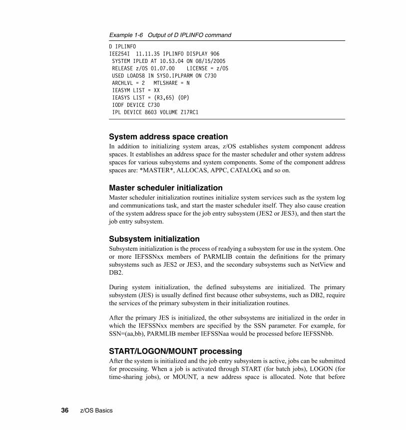
Example 1-6 Output of D IPLINFO command
D IPLINFO IEE254I 11.11.35 IPLINFO DISPLAY 906 SYSTEM IPLED AT 10.53.04 ON 08/15/2005 RELEASE z/OS 01.07.00 LICENSE = z/OS USED LOADS8 IN SYS0.IPLPARM ON C730 ARCHLVL = 2 MTLSHARE = N IEASYM LIST = XX IEASYS LIST = (R3,65) (OP) IODF DEVICE C730 IPL DEVICE 8603 VOLUME Z17RC1
System address space creationIn addition to initializing system areas, z/OS establishes system component addressspaces. It establishes an address space for the master scheduler and other system addressspaces for various subsystems and system components. Some of the component addressspaces are: *MASTER*, ALLOCAS, APPC, CATALOG, and so on.
Master scheduler initializationMaster scheduler initialization routines initialize system services such as the system logand communications task, and start the master scheduler itself. They also cause creationof the system address space for the job entry subsystem (JES2 or JES3), and then start thejob entry subsystem.
Subsystem initializationSubsystem initialization is the process of readying a subsystem for use in the system. Oneor more IEFSSNxx members of PARMLIB contain the definitions for the primarysubsystems such as JES2 or JES3, and the secondary subsystems such as NetView andDB2.
During system initialization, the defined subsystems are initialized. The primarysubsystem (JES) is usually defined first because other subsystems, such as DB2, requirethe services of the primary subsystem in their initialization routines.
After the primary JES is initialized, the other subsystems are initialized in the order inwhich the IEFSSNxx members are specified by the SSN parameter. For example, forSSN=(aa,bb), PARMLIB member IEFSSNaa would be processed before IEFSSNbb.
START/LOGON/MOUNT processingAfter the system is initialized and the job entry subsystem is active, jobs can be submittedfor processing. When a job is activated through START (for batch jobs), LOGON (fortime-sharing jobs), or MOUNT, a new address space is allocated. Note that before
36 z/OS Basics

LOGON, the operator must have started VTAM and TSO, which have their own addressspaces.
Figure 1-8 shows some of the important system address spaces and VTAM, CICS, TSO,a TSO user and a batch initiator. Each address space has 2 GB of virtual storage bydefault, whether the system is running in 31-bit or 64-bit mode.
Figure 1-8 Virtual storage layout for multiple address spaces
Recall that each address space is divided into various common and private storage areas.The private areas are available only to that address space, but common areas are availableto all.
During initialization of a z/OS system, the operator uses the system console or hardwaremanagement console, which is connected to the support element. From the systemconsole, the operator initializes the system control program during the NucleusInitialization Program (NIP) stage.
During the NIP stage, the system might prompt the operator to provide systemparameters that control the operation of z/OS. The system also issues informationalmessages that inform the operator about the stages of the initialization process.
1.9.2 IPL typesSeveral types of IPL exist; these are described as follows:
Started tasks
*MASTER*
PCAUTH
RASP
TRACE
. . .
CATALOG
CONSOLE
ALLOCAS
VLF
LLA
JES
VTAM
CICS
TSO
TSO
USER
INI
T /JOB
Batch job
TSO Logon
System and subsystem
address spaces
SMS
Chapter 1. Overview of system programming 37
� Cold start
An IPL that loads (or reloads) the PLPA and clears the VIO data set pages. The firstIPL after system installation is always a cold start because the PLPA is initiallyloaded. Subsequent IPLs are cold starts when the PLPA is reloaded, either to alter itscontents or to restore its contents if they were lost. This is usually done when changeshave been made to the LPA (for example, when a new SYSRES containingmaintenance is being loaded).
� Quick start
An IPL that does not reload the PLPA, but clears the VIO data set pages. (The systemresets the page and segment tables to match the last-created PLPA.) This is usuallydone when there have been no changes to LPA, but VIO must be refreshed. Thisprevents the warm start of jobs that were using VIO data sets.
� Warm start
An IPL that does not reload the PLPA, and preserves journaled VIO data set pages.This will allow jobs that were running at the time of the IPL to restart with theirjournaled VIO data sets.
Often, the preferred approach is to do a cold start IPL (specifying CLPA). The otheroptions can be used, but extreme care must be taken to avoid unexpected change orbackout of change. A warm start could be used when you have long-running jobs whichyou want to restart after IPL, but an alternative approach is to break down those jobs intosmaller pieces which pass real data sets rather than use VIO. Modern disk controllerswith large cache memory have reduced the need for VIO data to be kept for long periods.
Also, do not confuse a cold start IPL (CLPA would normally be used rather than the term“cold start”) with a JES cold start. Cold starting JES is something that is done extremelyrarely, if ever, on a production system, and totally destroys the existing data in JES.
1.9.3 Shutting down the systemTo shut down the system each task must be closed in turn, in the correct order. Onmodern systems, this is the task of the automation package. Shutting down the systemusually requires a single command. This will remove most tasks except Automationitself. The Automation task is closed manually, and then any commands needed toremove the system from a sysplex or serialization ring are issued.
Note: VIO is a method of using memory to store small temporary data sets forrapid access. However, unlike a RAM disk on a PC, these are actually backed upto disk and so can be used as a restart point. Obviously there should not be toomuch data stored in this way, so the size is restricted.
38 z/OS Basics

1.10 SummaryThe role of the z/OS system programmer is to install, customize, and maintain theoperating system.
The system programmer must understand the following areas (and more):� System customization� Workload management� System performance� I/O device configuration� Operations
To maximize the performance of the task of retrieving modules, the z/OS operatingsystem has been designed to maintain in memory those modules that are needed for fastresponse to the operating system, as well as for critical applications. Link pack area(LPA), linklist, and authorized libraries are the cornerstones of the fetching process.
Also discussed was the system programmer’s role in configuring consoles, setting upmessage-based automation, and using SMP/E to manages changes to the systemsoftware.
System start-up or IPL was introduced with the following topics:� IPL and the initialization process� Types of IPLs: cold start, quick start, and warm start� Reasons for IPLing
Key terms in this section
HCD IODF SYSRES
SMP/E linklist IPL
WTOR PARMLIB PROCLIB
system symbol PSA LPA
nucleus LOADPARM SQA
system library
Chapter 1. Overview of system programming 39

40 z/OS Basics
Chapter 2. Using SMP/E
Objective: As a z/OS system programmer, you will need to manage changes to thesystem software. You must ensure that software products and their modifications,service levels or fixes are properly installed at a specific level so that their interfacesand elements can work together with the operating system. As more products integrateand the system is enhanced, so, too, does the complexity of monitoring the elementsof the system increase. This is an extremely vital and critical role.
After completing this topic, you will be able to:� Explain how proper installation and maintenance are the basis for high availability
in the z/OS environment.
2
© Copyright IBM Corp. 2005. All rights reserved. 41

2.1 What is SMP/E?SMP/E is the basic tool for installing and maintaining software on z/OS and its relatedsubsystems and middleware. It controls these changes at the component level by:� Selecting the proper level of code to be installed from a large number of potential
changes keeping the product software consistent� Calling system utility programs to install the changes� Keeping records of the installed changes by providing a facility to enable you to
inquire on the status of your software and to reverse the change if necessary.� All code and its modifications are located in the SMP/E database called the
Consolidated Software Inventory (CSI) made up of one or more VSAM data sets.� This function protects the integrity of the software.
SMP/E can be run either using batch jobs or using dialogues under Interactive SystemProductivity Facility/Program Development Facility (ISPF/PDF). SMP/E dialogs helpyou interactively query the SMP/E database, as well as create and submit jobs to processSMP/E commands.
2.2 The SMP/E view of the systemThe z/OS system overall view may appear to be one big block of code that drives theCPU. Although, z/OS and previous versions are highly complex comprising manydifferent smaller blocks of code. Each of those smaller blocks of code perform a specificfunction within the system.
Each system function is composed of one ore more load modules. In a z/OS environment,a load module represents the basic unit of machine-readable execution code (OperationCode). Load modules are created by combining one or more object modules and
RACF DB2 MVS CICS
ISPF TSO SMP/E EREP MQ
JES RMF HTTP IMS VTAM
WAS Netview DFSMS PSF RRS
RACF DB2 MVS CICS
ISPF TSO SMP/E EREP MQ
JES RMF HTTP IMS VTAM
WAS Netview DFSMS PSF RRS
42 z/OS Basics

processing them with a link-edit utility. The link-editing of modules is a process thatresolves external references (called routines) and addresses. The functions on yoursystem, therefore are one or more object modules that have been combined and link-edited.
To examine where the object module comes from, let’s take a look at this example:
At most times, object modules are sent to you as part of a product. In the above example,the object module MOD1 was sent as part of a product. Other times, you may need toassemble source code sent to you by the product packagers to create the object module.You can modify the source code and then assemble it to produce an object module. In thisexample SRCMOD2 is source code that you assemble to create object module MOD2.When assembled, you link edit object module MOD2 with object module MOD1 tocreate the load module LMOD1.
In addition, to object modules and source code, most products distribute many additionalparts such as macros, help-panels, CLISTs and other z/OS library members. Thesemodules, macros and other types of data and code are the basic building blocks of yoursystem. All of these building blocks are called elements. They also describes therelationship the software has with other products or services that may be installed on thesame z/OS system.
Chapter 2. Using SMP/E 43

2.3 Changing system elementsOver time, you may need to change some of the elements of your system. These changesmay be necessary to improve the usability or reliability of a product. You may want toadd some new functions to your system, upgrade some of the elements of the system, ormodify some elements for a variety of reasons. In all cases, you are making systemmodifications. In SMP/E, we refer to these system modifications as SYSMODs.
A SYSMOD is the actual package containing information SMP/E needs to install andtrack system modifications. SYSMOD are composed of two parts:� Modification Control Statement (MCS) designated by ++ as the first two characters,
that tells SMP/E:• What elements are being updated or replaced• How the SYSMOD relates to product software and other SYSMODs• Other specific installation information
� The Modification Text which is the object modules, macros and other elements supplied by the SYSMOD.
There are four different categories of SYSMODs, each supporting a task you might wantto perform:� Function SYSMOD - Introduce the element for a product� PTF SYSMOD (program temporary fix) - Prevent or fix problems with an element or
introducing a new element.� APAR SYSMOD (authorized program analysis report) - Fix problems with an
element.� USERMOD SYSMOD (user modification) - Customize an element.
2.4 Introducing an element into the system
One way you can modify your system is to introduce new elements into that system. Toaccomplish this with SMP/E, you can install a function SYSMOD. The functionSYMOD introduces a new product, a new version or release of a product, or updatedfunctions for an existing product into the system.
Important: All other types of SYSMODs are dependent upon the functionSYSMOD, because they are all modifications of the elements originally introduced bythe function SYSMOD.
44 z/OS Basics
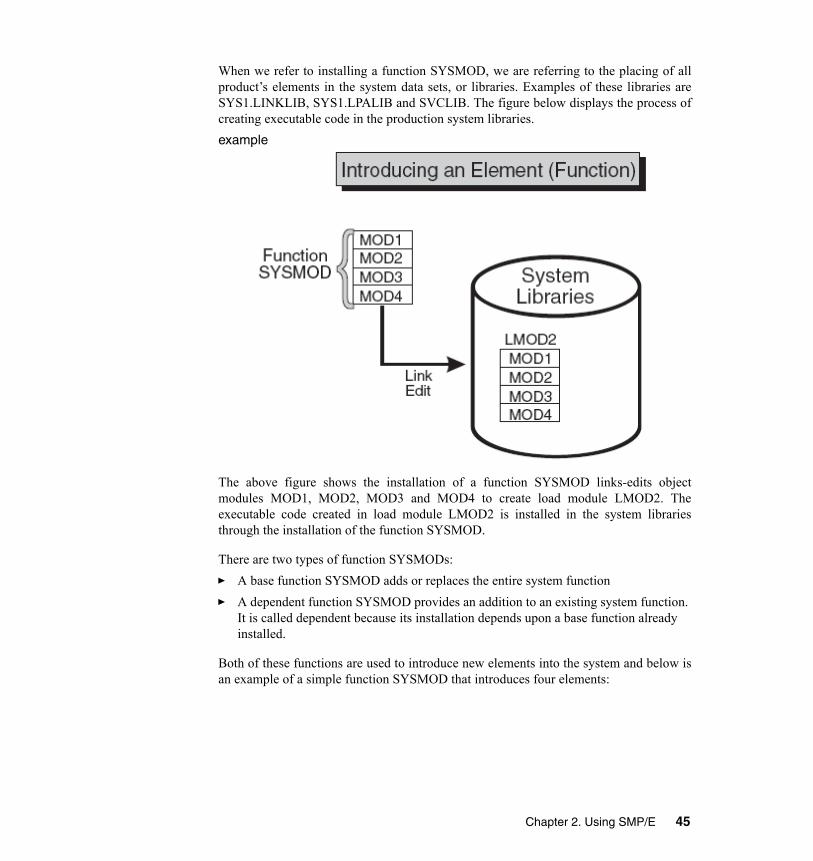
When we refer to installing a function SYSMOD, we are referring to the placing of allproduct’s elements in the system data sets, or libraries. Examples of these libraries areSYS1.LINKLIB, SYS1.LPALIB and SVCLIB. The figure below displays the process ofcreating executable code in the production system libraries. example
The above figure shows the installation of a function SYSMOD links-edits objectmodules MOD1, MOD2, MOD3 and MOD4 to create load module LMOD2. Theexecutable code created in load module LMOD2 is installed in the system librariesthrough the installation of the function SYSMOD.
There are two types of function SYSMODs:� A base function SYSMOD adds or replaces the entire system function� A dependent function SYSMOD provides an addition to an existing system function.
It is called dependent because its installation depends upon a base function already installed.
Both of these functions are used to introduce new elements into the system and below isan example of a simple function SYSMOD that introduces four elements:
Chapter 2. Using SMP/E 45

example
2.5 Preventing problems with an elementWhen a problem with a software element is discovered, IBM supplies its customers witha tested fix for that problem. This will come in a form of a program temporary fix (PTF).Although you may not have experienced the problem the PTF is intended to prevent, it iswise to install the PTF on your system. The PTF SYSMOD is used to install the PTF,thereby preventing the occurrence of that problem on your system.
Most PTFs are designed to update or replace one or more complete elements of a systemfunction. Here is a small example:
In the above diagram we see a previously installed load module, LMOD2. If we want toreplace the element MOD1, we should install a PTF SYSMOD that contains the module
46 z/OS Basics

MOD1. That PTF SYSMOD replaces the element in error with the corrected element. Aspart of the installation of the PTF SYSMOD, SMP/E relinks LMOD2 to include the newand corrected version of MOD1.
Here is an example of a simple PTF SYSMOD:
PTF SYSMODs are always dependent upon the installation of a function SYSMOD. Insome cases, some PTF SYSMODs may also be dependent upon the installation of otherPTF SYSMODs. These dependencies are called prerequisites. We will look at the typicalPTF prerequisite when we discuss the complexity of keeping track of the elements of thesystem.
2.6 Fixing problems with an elementAt times, you will find it necessary to correct a serious problem that occurs on yoursystem before a PTF is ready for distribution. Therefore, in this circumstance, IBMsupplies you with an authorized program analysis report (APAR). An APAR is a fixdesigned to correct a specific area of an element or replace an element in error. Youinstall an APAR SYSMOD to implement a fix, therefore updating the incorrect element.
Note: From the above example we will describe Distribution Libraries later.
Chapter 2. Using SMP/E 47

The processing of the APAR SYSMOD provides a modification for the object moduleMOD2. During the installation of the APAR SYSMOD, MOD2 is updated (andcorrected) in LMOD2.
The APAR SYSMOD always has the installation of a function SYSMOD as aprerequisite and can also be dependent upon the installation of other PTFs or APARSYSMODs.
2.7 Customizing an element - USERMOD SYSMODIf you have a requirement for a product to perform differently than what it was intendedto, you can consider a customized element for that system. IBM provides certain modulesallowing you to adapt IBM code for your specific requirements. After you make thedesired modifications, you place these modules into your system by installing aUSERMOD SYSMOD. This SYSMOD can be used to replace or update an element or tointroduce a totally new written element into your system. In all circumstances, the
48 z/OS Basics

USERMOD SYSMOD is created by you either to modify IBM code or to add your owncode to the system.
Here we see that MOD3 has changed through a USERMOD SYSMOD.
Below is the example of a USERMOD SYSMOD
2.7.1 Prerequisites and corequisitesAgain, a function SYSMOD is a prerequisites for APARs, PTFs and USERMODs.Sometimes a PTF or even an APAR is dependent upon other PTF SYSMODs called
Note: For a USERMOD SYSMOD there might be a prerequisite for the installation ofa function SYSMOD and possibly the installation of other APARs, PTFs orUSERMOD SYSMODs.
Chapter 2. Using SMP/E 49

corequisites. Here we begin to see the complexity of elements and SYSMODdependencies. In order to keep track of hundreds of modules in many system libraries wefinally now understand the need for SMP/E tooling. Keeping track of these componentsand changes become very apparent when we examine the z/OS maintenance processsince you can see how a PTF can contain multiple elements to replace.
2.8 Tracking and controlling elementsThe means for SMP/E to track and control elements successfully is to identify themuniquely. This is where we use the modification identifiers and there are three types. � Function Modification Identifiers (FMIDs) identify the function SYSMOD that
introduces the element into the system.� Replacement Modification Identifiers (RMIDs) identify the last SYSMOD (in most
cases a PTF SYSMOD) to replace an element.� Update Modification Identifiers (UMIDs) which identifies the SYSMOD that an
update to an element since it was last replaced.
2.9 Working with SMP/EThe SMP/E process is performed by three simple basic commands, (RECEIVE, APPLY,ACCCEPT). Before we explore these command we will look at Libraries that are used toimplement the process. There are two types of libraries. The Distribution and TargetLibraries.
The Distribution Libraries (DLIBs) contains all the elements used for input and is alsoused for backup. In the case of an error with a Production element, the element can bereplaced from these libraries.
The Target Libraries (TLIBs) contain all the executables required to run the system.
As mentioned earlier the Consolidated Software Inventory (CSI) is where SMP/E keepstrack of SYSMODs composed of one or more VSAM KSDS data sets. These are dividedinto zones that contain groupings of records or their installation status describing theSYSMOD and their associated elements called entities.
The elements found in the distribution libraries are contained in the distribution zone andentry elements found in the target libraries are contained in the target zone. In addition tothese zones the CSI contains a global zone.
The Global Zone provides:� The options found for SMP/E processing
50 z/OS Basics

� Status information for all SYSMODs in process� Entries required to identify and describe each Target and Distribution zone� Special exception handling for SYSMOD in error.
The exception data handling is very important. It is referred to as HOLDDATA and is usu-ally supplied for a product to indicate that the SYSMOD should not be processed or heldfor installation. In these cases the cause can be:
• Performing some action before installing the SYSMOD (USER HOLD)• The PTF is in error and awaiting correction (ERROR HOLD)• The system needs to perform an action before it is installed (SYSTEM HOLD)
All the information located in the Global Zone, combined with the information found inthe Target and Distribution Zones make up the data SMP/E requires to install and trackthe system’s software. It contain a great deal of information. All this information can bedisplayed using:� The LIST command creating a hard copy which lists information about the system� REPORT command which checks, compares, and also generates a hardcopy of the
information about zone content� QUERY Dialogues via ISPF� SMP/E CSI API which can be used to write application programs to query the content
of the system.
2.9.1 SMP/E basic commands
RECEIVEThe RECEIVE process is used to take a SYSMOD which is outside of SMP/E and stagethem into the SMP/E Library domain which begins to construct the CSI entries that
CSIDistribution
Zone
CSIGlobalZone
CSITargetZone
TLIBs DLIBs
CSIDistribution
Zone
CSIGlobalZone
CSITargetZone
TLIBs DLIBs
Chapter 2. Using SMP/E 51

describe them. This allows them to be queried for input into later processes. Morerecently the source can be electronic from a web site, although usually it comes from atape or even a third party vendor media.
This process’s role accomplishes several tasks:� Constructs entries in the Global Zone for describing the SYSMOD� Ensuring the SYSMOD is valid such as the syntax for modification control
statements (MCS) associated to the products installed in the CSI� Installing the SYSMOD into the libraries. As an example the PTF temporary store
library.� Assessing the HOLDDATA to ensure errors are not introduced.
During the RECEIVE processing the MCS for each SYSMOD is copied to an SMP/Etemporary storage area called the SMPPTS data set containing the inline elementreplacement or update for that SYSMOD.
SMP/E updates the global zone with information about the SYSMODs that is hasreceived:
Note: There are also RELFILEs which package the elements in relative files that areseparate from MCSs which are mostly used by function SYSMODs. Relative files arestored in another temporary storage area called SMPTLIB data sets.
52 z/OS Basics

Figure 2-1
In the course of maintaining the system, you need to install service and process therelated HOLDDATA. Assume IBM has supplied you with a service tape (such as aCBPDO or ESO tape) and you want to install it on the system. The first step is to receivethe SYSMODs and HOLDDATA that are contained on the tape by:
SET BDY(GLOBAL)RECEIVE
Use of these commands, SMP/E receives all the SYSMODs and HOLDDATA on thetape.
In order to RECEIVE only SYSMODs for installation into the Global Zone:SET BDY(GLOBAL)RECEIVE SYSMODS
Note: To RECEIVE only HOLDDATA that may require special handling or that are inerror you can use this command. It is important that you receive HOLDDATA intoSMP/Es repository as soon as possible.
SET BDY(GLOBAL)RECEIVE HOLDDATA
SMPPTSMCS Entries
Global ZoneSYSMOD ENTRIESHOLDDATA ENTRIES
SMPTLIBRELATIVE FILES
web site R
ECEI
VE
TargetLibraries
TargetZone
Distribution Libraries
Distribution Zone
SMPPTSMCS Entries
Global ZoneSYSMOD ENTRIESHOLDDATA ENTRIES
SMPTLIBRELATIVE FILES
web site R
ECEI
VE
TargetLibraries
TargetZone
Distribution Libraries
Distribution Zone
Chapter 2. Using SMP/E 53

For SYSMODs for a specific product (for example, WebSphere Application Server forz/OS) including HOLDDATA:
SET BDY(GLOBAL)RECEIVE FORFMID(H28W500)
APPLYThe APPLY process instructs SMP/E which of the received SYSMODs are to be selectedfor installation in the target libraries (TLIBs). SMP/E also ensures that all other requiredSYSMODs (prerequisites) have been installed or are being installed concurrently as wellas in the proper sequence. The source of the elements is the SMPTLIB data sets, theSMPPTS data set or indirect libraries depending on how is was packaged. This phase ofthe SMP/E process entails:� Executing the appropriate utility to install the SYSMOD into the target library
depending on the type of input text supplied and target module being changed.� Ensuring the relationship of the new SYSMOD is correct with other SYSMODs in
the target zone.� The CSI is modified displaying the updated modules.
The Target zone reflects the content of the target libraries so therefore, after the utility iscompleted and zone updated it will accurately reflect the status of those libraries.
Important: The APPLY command updates the system libraries and should becarefully used on a live Production System. We recommend to initially use a copy ofthe Production Target Libraries and Zones.
54 z/OS Basics

The APPLY processing is where the target zone is accurately updated:� All SYSMOD entries in the Global Zone are updated to reflect that the SYSMOD has
been applied to the target zone� The target zone accurately reflects each SYSMOD entry applied. Element entries
(such as MOD and LMOD) are also created in the target zone.� BACKUP entries are created in the SMPSCDS data set to the SYSMOD can be
restored, if at all necessary.
Similar to the RECEIVE process the APPLY command has many different operands forflexibility to select SYSMODs you would like to see for installation in the target librariesand provides an assortment of output. The directives used instruct SMP/E what you wantinstalled.
To install only PTF SYSMODs:SET BDY(ZOSTGT1)APPLY PTFS.
In order to select PTF SYSMODs, you name them in the directives:
TargetLibraries
TargetZone
SMPPTS
Global ZoneSYSMOD ENTRIES
Updated !
SMPTLIB
Distribution Libraries
Distribution Zone
{APPLY
SYSMODs EntriesELEMENTs Created
TargetLibraries
TargetZone
SMPPTS
Global ZoneSYSMOD ENTRIES
Updated !
SMPTLIB
SMPPTS
Global ZoneSYSMOD ENTRIES
Updated !
SMPTLIB
Distribution Libraries
Distribution Zone
{APPLY
APPLY
SYSMODs EntriesELEMENTs Created
Chapter 2. Using SMP/E 55

SET BDY(ZOSTGT1)APPLY SELECT(UZ00001, UZ00002).
In some instances you may only want to install just corrective fixes (APARS) or usermodifications (USERMODs) into the target library:
SET BDY(ZOSTGT1)APPLY APARS
USERMODS.
In other instances you may want to update a selected product from a distribution tape:SET BDY(ZOSTGT1).APPLY PTFS
FORFMID(H28W500).
or
SET BDY (ZOSTGT1).APPLY FORFMID(H28W500).
Using APPLY CHECKThere may be times when you want to see which SYSMODs are included before youactually install them. You can do this with the CHECK operand by entering commandssuch as the following: SET BDY(MVSTGT1)APPLY PTFSAPARSFORFMID(HOP1)GROUPEXTEND CHECK
After these commands are processed, you can check the SYSMOD Status report to seewhich SYSMODs would have been installed if you had not specified the CHECKoperand. If you are satisfied with the results of this trial run, you can enter the commandsagain, without the CHECK operand, to actually install the SYSMODs.
ACCEPTOnce the SYSMOD has been installed into its Target library and “tested” it then isACCEPTed. This step is very similar to the APPLY that is taking the selected SYSMODsand installing them into the associated Distribution libraries. You specify operands on theACCEPT command that tell SMP/E which of the received SYSMODs are to be selectedfor installation. During this phase SMP/E also ensures that the correct functional level ofeach element is selected.
Attention: In the two cases above, SMP/E applies all applicable PTFs for the FMID.Unless you specify otherwise, PTFs are the default SYSMOD type.
56 z/OS Basics

The ACCEPT performs the follow tasks:� CSI entries are updated with the targeted elements in the Distribution Zone.� The targeted elements are either rebuilt or created in the Distribution libraries using
the content of the SYSMOD as input depending on the utility� Similar to the APPLY, it will verify the Target Zone CSI entries for the affected
modules and SYSMODs ensuring they are consistent with the library content� Performs housekeeping of obsolete or expired elements. It will delete the Global
Zone CSI entries, PTS members and SMPTLIBs for those SYSMODs affected. As an example Global zone SYSMOD entries and MCS statements in the SMPPTS data set are deleted for those SYSMODs that have been accepted into the Distribution zone.
Important: There is a “stop” ACCEPT processing that SMP/E provides so you canensure all prerequisites are satisfied before the installation of the SYSMODs. This is scheck for you to see what will happen (assist you in detecting problems) withoutactually modifying the Distribution libraries.
Note: If you wish that SMP/E does not perform the Global zone clean up, youhave the option to indicate this and the information is saved.
Chapter 2. Using SMP/E 57

Figure 2-2
After applying the SYSMODs into the Target zone, you can then tell SMP/E to installonly the eligible PTF SYSMODs into the Distribution zone:
SET BDY(ZOSDLB1).ACCEPT PTFS.
To install PTF SYSMODS selecting the particular ones:SET BDY(ZOSDLB1)ACCEPT SELECT(UZ00001,UZ00002).
Important: Should the SYSMOD be in error, do not ACCEPT it. By using theRESTORE process that takes the modules updated by the selected SYSMOD andrebuilds the copies in the Target libraries from the specific modules in the Distributionlibraries as input. Also the RESTORE updates the Target zone CSI entries to reflectthe removal of the SYSMOD. When ACCEPT processing is completed, there is noway it can be backed out, therefore the changes are permanent.
SMPPTSMCS Entries“deleted”
Global ZoneSYSMOD ENTRIES
“deleted”
SMPTLIBRELATIVE FILES
TargetLibraries
TargetZone
Distribution Libraries
Distribution Zone
SYSMOD EntriesElement Entries
“created”
ACCEP T
}SMPPTSMCS Entries“deleted”
Global ZoneSYSMOD ENTRIES
“deleted”
SMPTLIBRELATIVE FILES
TargetLibraries
TargetZone
Distribution Libraries
Distribution Zone
SYSMOD EntriesElement Entries
“created”
Distribution Libraries
Distribution Zone
SYSMOD EntriesElement Entries
“created”
ACCEP T
}
58 z/OS Basics

There are situations where you may want to update a particular product with allSYSMODs:
SET BDY(ZOSDLB1)ACCEPT PTFS
FORFMID(H28W500).
or
SET BDY(ZOSDLB1)ACCEPT FORFMID(H28W500).
ACCEPTING Prerequisite SYSMODsWhen installing a SYSMOD, you may not know if it has prerequisites. SOmetime anERROR SYSMOD is held). In these situations, you can direct SMP/E to check whetheran equivalent (or superseding) SYSMOD is available by specifying theGROUPEXTEND operand:
SET BDY(ZOSDLB1).ACCEPT PTFS
FORFMID(H28W500)GROUPEXTEND.
A good way to see which SYSMODs are included before you actually install them is byusing the CHECK operand:
SET BDY(ZOSTGT1).ACCEPT PTFS
FORMFMID(H28W500)GROUPEXTENDCHECK.
ACCEPT ReportingWhen this last phase is completed., these reports will assist you to assess the results:� SYSMOD Status Report - provides a summary of the processing that took place for
each SYSMOD, based on the operands you specified on the ACCEPT command.� Element Summary Report - provides you with a detailed look at each element
affected by the ACCEPT processing and which libraries installed
Note: The the two cases above, SMP/E accepts all applicable PTFs for the productwhose FMID is H28W500 located in the Distribution zone ZOSDLB1.
Note: If SMP/E can not find a required SYSMOD, it looks for and uses aSYSMOD that supersedes the required one.
Chapter 2. Using SMP/E 59

� Causer SYSMOD Summary Report - provides a list of SYSMODs which caused other SYSMODs to fail and descries the errors that must be fixed in order to be successfully processed.
� File Allocation Report - provides a list of the data sets used for the ACCEPT processing and supplies information about these data sets.
Overall SMP/E process flow
Figure 2-3
CSIDistribution
Zone
CSIGlobalZone
CSITargetZone
TLIBs DLIBsSMPTLIBs
PTS
RECEIVE APPLYACCEPT
RESTORE
CSIDistribution
Zone
CSIGlobalZone
CSITargetZone
TLIBs DLIBsSMPTLIBs
PTS
RECEIVE APPLYACCEPT
RESTORE
60 z/OS Basics

Example of CSI VSAM Cluster Definition
Figure 2-4
Chapter 2. Using SMP/E 61

SMP batch Job example
Figure 2-5
New section starts here:
2.10 When is SMP/E used?The system programmer responsibilities include base z/OS and IBM software productproblem determination and resolution. When a problem is reported, the systemprogrammer must determine whether the problem is the result of local customization orthe problem is with IBM code. The systems programmer will call IBM defect supportwhen IBM code is suspect. Typically, defect support will recommend a fix for thesystem. The systems programmer would use SMP/E to verify the status of this fix on thesystem. If the fix is absent, then SMP/E would be used to ‘receive’ and ‘apply’ the fix.
62 z/OS Basics
To avoid problems, the systems programmer should routinely apply the latest collectionof fixes to the base z/OS and other IBM software products. The most aggressive schedulewould be monthly, however, it is common for this schedule to be quarterly orsemi-annual.
A new or modified business application might expose an IBM code defect. When thisoccurs, IBM defect support would provide the systems programmer a fix to apply. Thefix may require pre-requisite fixes. This can be time consuming and you, the systemsprogrammer, are on a visible critical path. It can bring a significant amount of negativeattention. Applying routine maintenance to the system can avoid this situation.
It is in the best interest of the business and the systems programmer to reduce the amountof time required to resolve a code defect which surfaced in your business productionenvironment. A suggested fix may already be applied, therefore, it is immediately knownthat the problem has not been adequately identified. The best system programmers planand execute activities which keep them from being on the critical path of processingmission critical business workload, installation of new equipment and businessopportunities made possible by exploiting previously unused software feature andfunctions.
2.11 Why is SMP/E used?SMP/E provides an excellent inventory, cross-reference of software dependencies andmechanism for applying software maintenance. This insures integrity of the overallsystem. The mechanics of using SMP/E to maintain a system can be quite simple andeasy. How SMP/E works and the knowledge needed to package fixes and softwareproducts for SMP/E is significantly complex. IBM provides instructions to follow withall SMP/E packaged fixes, software upgrades and products. The system programmerfollows the instructions shipped with the fix, upgrade or product.
2.12 TerminologyAs is the case with many technical, scientific and medical disciplines, terminology is thekey to describing, understanding and being skilled with a specific discipline. SMP/E fallsinto this category. We will briefly discuss SMP/E specific terminology, then how asystem programmer uses SMP/E. Reference Figure 2-6 on page 2-67 as you read throughthis terminology section.
2.12.1 Communicating with IBM Defect SupportDefect support will typically recommend a ‘PTF’ to fix a problem. The systemprogrammer would use SMP/E to determine absence or presence of the ‘PTF’ which is
Chapter 2. Using SMP/E 63

uniquely identified by a seven digit alphanumeric string such as UQ80526. A ‘PTF’ fallsinto an SMP/E classification called ‘SYSMOD’. If the problem is identified as a newlyreported IBM code defect with no code fix, then IBM opens an ‘APAR’. � PTF - Program Temporary Fix
When a problem with a software element is discovered, IBM supplies its customerswith a tested fix for that problem. This fix comes in the form of a program temporaryfix (PTF). Although you may not have experienced the problem the PTF is intendedto prevent, it is wise to install the PTF on your system. The PTF SYSMOD is used toinstall the PTF, thereby preventing the occurrence of that problem on your system.Usually, PTFs are designed to replace or update one or more complete elements of asystem function.
� APAR - Authorized Program Analysis Report
In critical situations, a code fix or problem bypass will be provided in the form of anAPAR fix. The code will then be officially tested and made generally available in theform of a PTF. The APAR fix would, then be replaced by the PTF.
� SYSMOD - System Modification
Software, whether it is a product or service, consists of elements such as macros,modules, source, and other types of data (such as CLISTs or sample procedures). Forsoftware to be installed by SMP/E, it must include control information (SMP/Einstructions) for the elements. The combination of elements and control informationis called a system modification, or SYSMOD. PTFs and APARs are bothSYSMODs
Defect support may inquire about your systems ‘PUT level’ before starting, so they havea general idea which PTFs are applied. The system programmer should be able to useSMP/E to determine the PUT level immediately.� PUT level - Program Update Tape
Approximately once a month, IBM makes an accumulation of the latest PTFsavailable on tape. Applying this accumulation of PTFs is called a PUT level update.Generally, PUT levels are in the form of YYMM such as PUT0409, September 2004.However, it is possible that PUT levels will skip a couple months during the year.When this occurs, PUT0409, represents the 9th PUT level during 2004. Defectsupport will know how to interpret the meaning of the PUT level you provide.
2.12.2 Consolidate Software Inventory (CSI) and zonesSMP/E is a collection of data sets (aka libraries) which are all inter related. Thiscollection of data sets includes the ‘target’ libraries which are used to load and run thesystem. When the system is initially installed, the target libraries are created from a copyof the ‘distribution’ libraries. PUT levels and PTFs will are ‘APPLIED’ to the targetlibraries. Once a system programmer is confident the PTFs or PUT level will not need to
64 z/OS Basics
be backed out of the system, this software maintenance will be ‘ACCEPTED’ into thedistribution libraries. The collection of target libraries is given a ‘Target Zone’ name andthe collection of distribution libraries is given a ‘Distribution Zone’ name.� Target Zone
A name given to the collection of all elements (modules, macros, source, ISPF panels,etc.) used to maintain and run the system. The SMP/E command to update the targetzone is APPLY.
� Distribution Zone
A name given to a collection of all elements (modules, macros, source, ISPF panels,etc.) used for initial system build, then used to restore elements resulting from a backout of elements applied to the target zone. The SMP/E command to update(permanently commit) changes to the distribution zone is ACCEPT.
Before software maintenance can be applied to the target zone, the software maintenancemust be ‘RECEIVED’ in the Global Zone. As you might expect with a name likeglobal, it has a significant amount of information related to the subordinate target anddistribution zones, however, it is not directly involved in the operational system.� Global Zone
A name given to data sets and records within those data sets used for updating andtracking status of previous updates to the target and distribution zones as well as thelocation used to ‘receive’ maintenance. The global zone also contains informationthat (1) enables SMP/E to access target and distribution zones, and (2) enables you totailor aspects of SMP/E processing.
SMP/E uses ‘CSIs’ to keep records of the system. The CSI includes everything we justread about in this terminology section. � CSI - Consolidated Software Inventory
The CSI keeps track of all elements found in the aggregate of global, target anddistribution libraries or zones.
2.12.3 MaintenanceBefore or during SMP/E execution to receive maintenance, it is best to apply the‘HOLDDATA’. The holddata will identify new list of ‘PE’ PTFs, changes topre-requisite dependencies, comments, documentation changes and actions required as aresult of applying specific PTFs.� PE - PTF in Error
Any code or elements applied via PTF packaging found to have a problem is markedwith a PE status. The code and elements associated with a PE PTF will not be applied.
� HOLDDATA
Chapter 2. Using SMP/E 65

By receiving the HOLDDATA as soon as possible, you make sure SMP/E has themost current information available. Therefore, if you try to install any PTF inresponse to a problem on your system and that PTF is in error, SMP/E knows this andwarns you so you can weigh the effect of installing the known problem against theeffect of fixing the problem you have encountered. Several different HOLD reasonsexists:
• Performing some action before installing the SYSMOD (USER HOLD)• The PTF is in error and awaiting correction (ERROR HOLD)• The system needs to perform an action before it is installed (SYSTEM HOLD)
Once the maintenance is successfully received and all USER and SYSTEM HOLDs areaddressed, then the elements embedded in this PTF or PUT level maintenance is appliedto the target libraries. SMP/E JCL does not explicitly have DD statements for each targetlibrary because it is not practical. SMP/E makes use of DDDEFs located in the CSIinstead of having JCL DD statement coded for each and every target library.� DDDEF - DDname Definition
The SMP/E instructions include a ddname as the storage location for new elements orupdated elements. SMP/E maintains a list of DDDEF entries which include theddname with associated data set name or HFS file. This DDDEF entry is used toresolve the ddname allocation request.
66 z/OS Basics

Figure 2-6 Flow of SMP SYSMOD Processing
SMP/E ‘Service’ is a term inclusive of APARs, PTFs, PUT Levels, PE PTFs andHOLDDATA. Service can be obtained electronically via the intranet. SMP/E ‘CBPDO’is a full product update. IBM also packages a complete operating system with selectedproducts pre-installed for installation without the need to use SMP/E. This is called aServerPac.
2.13 Local SMP/E Environments
2.13.1 Production, Test and Emergency FixIt is common and recommended that fixes never be applied directly to a productionsystem. A typical SMP/E environment may consists of three mutually exclusive copies ofthe SMP/E libraries that contain the software used by the z/OS system. All three copieswill be identical initially. The three SMP/E environments are needed for 1) theproduction system, 2) a test system containing the next scheduled update of all newlyidentified fixes, and 3) a mirror copy of the production SMP/E libraries to receive,
Chapter 2. Using SMP/E 67

apply and test an emergency fix before introducing the fix into the productionenvironment.
2.13.2 Base z/OS and Product CSIsIt is common and recommended to define an SMP/E CSI environment for the base z/OSand separate SMP/E CSI environments for each product. The base z/OS and optionalproducts typically are shipped with instructions and JCL to define the SMP/E CSI foreach individually. Creating a separate SMP/E CSI for a new product install is a matter offollowing instructions and submitting JCL provided with the product.
2.14 How to use SMP/ESMP/E can be run either using batch jobs or using dialogues under Interactive SystemProductivity Facility (ISPF). SMP/E dialogues help you interactively query the SMP/Edatabase, as well as create and submit jobs to process SMP/E commands. Batch facilitiesare best for receiving, applying and accepting maintenance while ISPF facilities are bestto use while working with IBM defect support to answer questions about software levelsand presence or absence of specific PTFs. We will first discuss submitting SMP/E JCLand commands in batch, then SMP/E from ISPF.
2.14.1 SYSMODA SYSMOD is the actual package containing instructions SMP/E needs to install andtrack system modifications. SYSMOD are composed of two parts:� Modification Control Statement (MCS) designated by ++ as the first two characters,
that tells SMP/E:• What elements are being updated or replaced• How the SYSMOD relates to product software and other SYSMODs• Other specific installation information
Maintenance and products can be installed without coding any MCS statements. TheMCS statements are created by whoever packaged the maintenance or product. SMP/E‘commands’ are used to tell the SMP/E program where to locate and read these MCSinstructions packaged with the system elements. You may frequently see SYSMOD andPTF used interchangeably, however, there is a difference. PTF is the most common typeof SYSMOD.
68 z/OS Basics

2.14.2 JCLThe SMP/E JCL and commands are very simple as a result of all the target, distributionand work data sets allocation using DDDEF entries. The JCL below could be used toreceive sysmods and holddata into the MVS global zone.
//SMPJCL EXEC PGM=GIMSMP,// PARM='CSI=MVS.GLOBAL.CSI' //SMPPTFIN DD DSN=//SMPHOLD DD DSN=//SMPLOG DD SYSOUT=*//SMPCNTL DD *
SET BOUNDARY(GLOBAL).RECEIVE.
The SMP/E program, GIMSMP, is passed the name of the data set which is the globalCSI, MVS.GLOBAL.CSI in this case. The SMP/E program needs several input andoutput ddnames. SMP/E will expect to read instructions and sysmods from the data setname associated with SMPPTFIN ddname and it will expect to read holddata from dataset name associated with SMPHOLD ddname. SMP/E will write its message toSMPLOG ddname. SMPCNTL provides the SMP/E its commands. The SET commandtells SMP/E which zone that the following commands are directed. In this case SMP/E istold the following commands are intended for the global zone.
2.14.3 RECEIVE CommandThe RECEIVE command directed to the global zone will 1) read sysmods withinstructions, 2) read holddata, 3) write holddata and sysmods with instructions toSMPPTS DDDEF data set 4) write SMP/E messages and 5) update the global data setwith information about what it received. When completed, the global data set will showdate, time and status for each sysmod successfully received.
2.14.4 APPLY CommandThe only input and output hardcoded JCL ddnames used to APPLY sysmods is theSMPCNTL which provides SMP/E program its commands and ddname to writemessages. The SET BOUNDRY command is directing following commands to MVSTtarget zone. The target zone name is arbitrarily chosen by the system programmer.
//APPLY EXEC PGM=GIMSMP,// PARM='CSI=MVS.GLOBAL.CSI'//SYSPRINT DD SYSOUT=*//SMPLOG DD SYSOUT=*//SMPCNTL DD * SET BOUNDARY(MVST). APPLY SELECT(UW85091,UW85613) GROUPEXTEND COMPRESS(ALL)
Chapter 2. Using SMP/E 69

BYPASS(HOLDSYSTEM) CHECK.
The above APPLY command will 1) take ‘selected’ sysmods from the global zoneSMPPTS data set, 2) read the instructions and elements packaged in the sysmods and 3)execute the instructions which will result in adding, replacing and modifying elements inthe target libraries. Several operands are present on the APPLY command. Specific PTFsysmods are SELECTed to be applied. The GROUPEXTEND operand tells the programto include any required prerequisite or corequisite sysmods that have been received butnot specifically selected. COMPRESS(ALL) tells the program to regain unused space ina target library when needed. BYPASS(HOLDSYSTEM) tells the program that thesystem programmer has taken all specified system actions included as comments on thespecific sysmods in SYSTEM HOLD status. CHECK tells the program this is a trial runand please produce messages that would indicate probably of failure or success once theCHECK is removed.
ISPF
2.14.5 ACCEPT CommandOnce the system programmer is confident the applied sysmods will not be backed out,the same JCL used to APPLY is used to permanently ACCEPT the changes. Again, inthis case ACCEPT commands is directed to the distribution zone with a given name,MVSD.
SET BOUNDARY(MVSD)ACCEPT SELECT(UW85091,UW85613).
2.14.6 LIST CommandThe same JCL used for APPLY processing can be used. The LIST command can bedirected to the global, target or distribution zone to produce a listing of all known PTFs,selective PTFs along with their status (receive, applied, superseded and accepted) orDDDEFs, etc. An example to list a single PTF (UW85091), list all PTFs and list allDDDEF entries in the target zone (MVST) follows.
SET BOUNDARY(MVST).LIST SYSMODS(UW85091).LIST SYSMODS.LIST DDDEF.
2.15 ISPFUsing ISPF SMP/E Panels is the best method to use when working with defectsupport....to answer questions about existing maintenance levels and to determinewhether or not a PTF or SYSMOD is applied.
70 z/OS Basics

Figure 2-7 on page 2-71 is an example of the SMP/E Primary Option Menu. Tutorial andPF1 help panels exist in this ISPF application.
Figure 2-7 SMP/E Primary Option Menu
IBM PTF packaging instructions typically associate a PTF number with a PUT level. ThePUT levels are given ‘SOURCEIDs’ names such as PUT0403. Therefore, if asked whatPUT is the latest PUT level for the base z/OS or an option software product, a‘SOURCEID’ query will help provide that information. Figure 2-8 on page 2-71 selectssourceid and Figure 2-9 on page 2-72 requests a zone to be selected for the sourceidquery. When working with IBM defect support, you want to always select the targetzone.
Figure 2-8 SourceID Query Selection - Location of PUT level information
Chapter 2. Using SMP/E 71

Figure 2-9 Query PUT levels within target zone
All SOURCEID PUT levels will be displayed among any other SOURCEIDs used byyou are within SMP/E packaging. Selecting a PUT level, Figure 2-10 on page 2-72, willdisplay all the PTFs included in the PUT level. In this example, approximately 20 PTFsare in the March 2004 PUT level. The latest SOURCEID PUT levels are may not includeall PTFs released for that PUT level. Applying an emergency fix may result in the PUTlevel SOURCEID addition in the CSI because it is the PUT level associated with the PTF.The PUT level SOURCEID would be fully populated with all PTFs in the PUT levelwhen routine maintenance is completed.
If any one of the PTFs from SOURCEID PUT0403, Figure 2-11 on page 2-73, thendetails about the individual PTF will be displayed, such as status with date and timeapplied, Figure 2-12 on page 2-73.
Figure 2-10 PUT Levels - Select PUT0403 Level - for included PTFs
72 z/OS Basics

Figure 2-11 List of PTFs within PUT level - Select a specific PTF from the PUT level
Figure 2-12 SYSMOD(PTF) status info within PUT Level
Chapter 2. Using SMP/E 73

A SYSMOD (PTF) can be queried directly for the SMP/E Primary Option Menu. After‘Query’ is selected from the Primary Menu, then the ‘zone’ (MVST), the type of entry(SYSMOD) and specific SYSMOD(PTF) number can be entered to display the details.Figure 2-13 on page 2-74
Figure 2-13 Query SYSMOD(PTF) directly w/o going through SourceID panels
2.16 Order and download IBM fixesWhile collections of PTFs are typically received from Product Update Tape, PUT, andentire product updates are typically received from tape, CBPDO, emergency fixes can beordered and download over the Internet. The order and download can typically becompleted in 15 minutes.
https://techsupport.services.ibm.com/server/login is an IBM web site, used by systemprogrammers. Any system programmer can register to order and download fixes. Thedownload includes instructions. This web site is used to order z/OS, AIX, and OS/400fixes. The web site for all IBM servers.
2.17 SummaryA critical responsibility of the system programmer is to work with IBM defect supportwhen a problem surfaces in z/OS or option IBM products. Problem resolution willrequire the system programmer to receive and apply fixes to the enterprise system.
The SMP/E JCL and commands will be used frequently by a large enterprise z/OSsystem programmer, however, SMP/E MCS instructions will rarely be coded by the same
74 z/OS Basics

system programmer. The product and SYSMOD packaging will include the necessaryMCS statements.
Chapter 2. Using SMP/E 75

76 z/OS Basics

Chapter 3. Hardware systems and LPARs
3
Objective: As a new z/OS system programmer, you will need to develop a thoroughunderstanding of the hardware that runs the z/OS operating system. z/OS is designedto make full use of mainframe hardware and its many sophisticated peripheraldevices.
After completing this topic, you will be able to: � Discuss S/360 and zSeries hardware design.� Explain processing units and disk hardware.� Explain how mainframes differ from PC systems in data encoding.� List some typical hardware configurations.
© Copyright IBM Corp. 2005, 2006. All rights reserved. 77

3.1 Overview of mainframe hardware systemsThis topic provides an overview of mainframe hardware systems, with most of theemphasis on the processor “box.”
Related Reading: For detailed descriptions of the major facilities of z/Architecture, thebook z/Architecture Principles of Operation is the standard reference. You can find thisand other IBM publications at the z/OS Internet Library Web site:
http://www.ibm.com/servers/eserver/zseries/zos/bkserv/
Let’s begin this topic with a look at the terminology associated with mainframehardware. Being aware of various meanings of the terms systems, processors, CPs, andso forth is important for your understanding of mainframe computers.
In the early S/360 days a system had a single processor, which was also known as thecentral processing unit (CPU). The terms system, processor, and CPU were usedinterchangeably. However, these terms became confusing when systems becameavailable with more than one processor. This is illustrated in Figure 3-1.
Figure 3-1 Terminology overlap
Processor and CPU can refer to either the complete system box, or to one of theprocessors (CPUs) within the system box. Although the meaning may be clear from thecontext of a discussion, even mainframe professionals must clarify which processor or
Individual processors in the system
"processors"
"CPUs"
"engines"
"PUs"
"CPs"
IFLs, ICFs, zAAPs, IFLs spares
"system" = CPs running an operating system
System box from IBM possibly a zSeries
machine
Sometimes referenced as a "processor"
A few people use "CEC"
Many use "system"
Sometimes referenced as a "CPU"
78 z/OS Basics
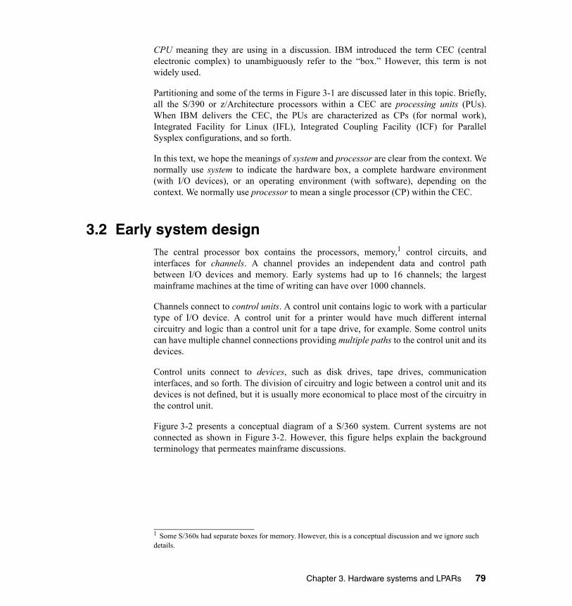
CPU meaning they are using in a discussion. IBM introduced the term CEC (centralelectronic complex) to unambiguously refer to the “box.” However, this term is notwidely used.
Partitioning and some of the terms in Figure 3-1 are discussed later in this topic. Briefly,all the S/390 or z/Architecture processors within a CEC are processing units (PUs).When IBM delivers the CEC, the PUs are characterized as CPs (for normal work),Integrated Facility for Linux (IFL), Integrated Coupling Facility (ICF) for ParallelSysplex configurations, and so forth.
In this text, we hope the meanings of system and processor are clear from the context. Wenormally use system to indicate the hardware box, a complete hardware environment(with I/O devices), or an operating environment (with software), depending on thecontext. We normally use processor to mean a single processor (CP) within the CEC.
3.2 Early system designThe central processor box contains the processors, memory,1 control circuits, andinterfaces for channels. A channel provides an independent data and control pathbetween I/O devices and memory. Early systems had up to 16 channels; the largestmainframe machines at the time of writing can have over 1000 channels.
Channels connect to control units. A control unit contains logic to work with a particulartype of I/O device. A control unit for a printer would have much different internalcircuitry and logic than a control unit for a tape drive, for example. Some control unitscan have multiple channel connections providing multiple paths to the control unit and itsdevices.
Control units connect to devices, such as disk drives, tape drives, communicationinterfaces, and so forth. The division of circuitry and logic between a control unit and itsdevices is not defined, but it is usually more economical to place most of the circuitry inthe control unit.
Figure 3-2 presents a conceptual diagram of a S/360 system. Current systems are notconnected as shown in Figure 3-2. However, this figure helps explain the backgroundterminology that permeates mainframe discussions.
1 Some S/360s had separate boxes for memory. However, this is a conceptual discussion and we ignore such details.
Chapter 3. Hardware systems and LPARs 79

Figure 3-2 Conceptual S/360
The channels in Figure 3-2 are parallel channels (also known as bus and tag channels,named for the two heavy copper cables they use). A parallel channel can be connected toa maximum of eight control units. Most control units can be connected to multipledevices; the maximum depends on the particular control unit, but 16 is a typical number.
Each channel, control unit, and device has an address, expressed as a hexadecimalnumber. The disk drive marked with an X in Figure 3-2 has address 132, derived asshown in Figure 3-3.
Figure 3-3 Device address
00 33 00 11
ProcessorsStorageControl
MainStorage
11 55 66 AA BB
ControlUnit
3Control
UnitControl
Unit
3
11 22
55 33Channels
Devices
X
Y 00 11 Z
ControlUnit
C0Communication
line
ParallelChannels
AnotherAnotherSystemSystem
Address: 1 3 2
Channel number Control unit number Device number
80 z/OS Basics

The disk drive marked with a Y in the figure can be addressed as 171, 571, or 671because it is connected through three channels. By convention the device is known by itslowest address (171), but all three addresses could be used by the operating system toaccess the disk drive. Multiple paths to a device are useful for performance and foravailability. When an application wants to access disk 171, the operating system will firsttry channel 1. If it is busy (or not available), it will try channel 5, and so forth.
Figure 3-2 contains another S/360 system with two channels connected to control unitsused by the first system. This sharing of I/O devices is common in all mainframeinstallations. Tape drive Z is address A31 for the first system, but is address 331 for thesecond system. Sharing devices, especially disk drives, is not a simple topic and there arehardware and software techniques used by the operating system to control exposuressuch as updating the same disk data at the same time from two independent systems.
As mentioned, current mainframes are not used exactly as shown in Figure 3-2 onpage 80. Differences include:
� Parallel channels are not available on the newest mainframes and are slowly being displaced on older systems.
� Parallel channels have been replaced with ESCON (Enterprise Systems CONnection) and FICON® (FIber CONnection) channels. These channels connect to only one control unit or, more likely, are connected to a director (switch) and are optical fibers.
� Current mainframes have more than 16 channels and use two hexadecimal digits as the channel portion of an address.
� Channels are generally known as CHPIDs (Channel Path Identifiers) or PCHIDs (Physical Channel IDs) on later systems, although the term channel is also correct. The channels are all integrated in the main processor box.
The device address seen by software is more correctly known as a device number(although the term address is still widely used) and is indirectly related to the control unitand device addresses.
3.3 Current designCurrent CEC designs are considerably more complex than the early S/360 design. Thiscomplexity includes many areas:
� I/O connectivity and configuration� I/O operation� Partitioning of the system
Chapter 3. Hardware systems and LPARs 81

3.3.1 I/O connectivityFigure 3-4 on page 83 illustrates a recent configuration. (A real system would have morechannels and I/O devices, but this figure illustrates key concepts.) Partitions, ESCONchannels, and FICON channels are described later.
Briefly, partitions create separate logical machines in the CEC. ESCON and FICONchannels are logically similar to parallel channels but they use fiber connections andoperate much faster. A modern system might have 100-200 channels or CHPIDs.2 Keyconcepts partly illustrated here include the following:
� ESCON and FICON channels connect to only one device or one port on a switch.� Most modern mainframes use switches between the channels and the control units.
The switches may be connected to several systems, sharing the control units and some or all of its I/O devices across all the systems.
� CHPID addresses are two hexadecimal digits.� Multiple partitions can sometimes share CHPIDs. Whether this is possible depends
on the nature of the control units used through the CHPIDs. In general, CHPIDs used for disks can be shared.
� An I/O subsystem layer exists between the operating systems in partitions (or in the basic machine if partitions are not used) and the CHPIDs.
An ESCON director or FICON switch is a sophisticated device that can sustain high datarates through many connections. (A large director might have 200 connections, forexample, and all of these can be passing data at the same time.) The director or switchmust keep track of which CHPID (and partition) initiated which I/O operation so thatdata and status information is returned to the right place. Multiple I/O requests, frommultiple CHPIDs attached to multiple partitions on multiple systems, can be in progressthrough a single control unit.
The I/O control layer uses a control file known as an IOCDS (I/O Control Data Set) thattranslates physical I/O addresses (composed of CHPID numbers, switch port numbers,control unit addresses, and unit addresses) into device numbers that are used by theoperating system software to access devices. This is loaded into the Hardware Save Area(HSA) at power-on and can be modified dynamically. A device number looks like theaddresses we described for early S/360 machines except that it can contain three or fourhexadecimal digits.
2 The more recent mainframe machines can have more than 256 channels, but an additional setup is needed for this. The channels are assigned in a way that only two hexadecimal digits are needed for CHPID addresses.
82 z/OS Basics

Figure 3-4 Recent system configuration
Many users still refer to these as “addresses” although the device numbers are arbitrarynumbers between x'0000' and x’FFFF’. The newest mainframes, at the time of writing,have two layers of I/O address translations between the real I/O elements and theoperating system software. The second layer was added to make migration to newersystems easier.
Modern control units, especially for disks, often have multiple channel (or switch)connections and multiple connections to their devices. They can handle multiple datatransfers at the same time on the multiple channels. Each device will have a unit controlblock (UCB) in each z/OS image.
I/O Processing
Othersystems
01 02 ... 40 41 42 ... ... A0 A1 ... ...
ControlUnit
ESCONDirector(switch)
FICONswitch
ControlUnit
C0Control
Unit
C1Control
Unit
01Control
Unit
02
E - ESC ON channelF - FICON channelO - OSA-Express channel
CEC box
Partition 1 Partition 2
LAN
O E E E E F F
Channels(CHPIDs or PCHIDs)
Control unit addresses (CUA)
00 1100 11Unit addresses (UA)
01
00 11 00 11
Chapter 3. Hardware systems and LPARs 83
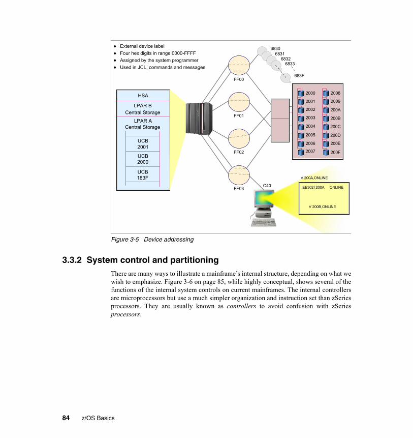
Figure 3-5 Device addressing
3.3.2 System control and partitioningThere are many ways to illustrate a mainframe’s internal structure, depending on what wewish to emphasize. Figure 3-6 on page 85, while highly conceptual, shows several of thefunctions of the internal system controls on current mainframes. The internal controllersare microprocessors but use a much simpler organization and instruction set than zSeriesprocessors. They are usually known as controllers to avoid confusion with zSeriesprocessors.
HSA
LPAR BCentral Storage
LPAR ACentral Storage
UCB2001
UCB2000
UCB183F
68306831
68326833
FF00
FF01
FF02
FF03 C40
683F
2000
2001
2002
2003
2004
2005
2006
2007
2008
2009
200A
200B
200C
200D
200E
200F
External device labelFour hex digits in range 0000-FFFFAssigned by the system programmerUsed in JCL, commands and messages
IEE302I 200A ONLINE
V 200B,ONLINE
V 200A,ONLINE
84 z/OS Basics
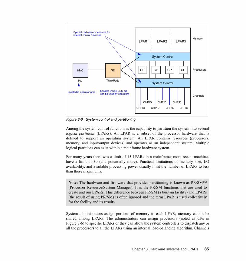
Figure 3-6 System control and partitioning
Among the system control functions is the capability to partition the system into severallogical partitions (LPARs). An LPAR is a subset of the processor hardware that isdefined to support an operating system. An LPAR contains resources (processors,memory, and input/output devices) and operates as an independent system. Multiplelogical partitions can exist within a mainframe hardware system.
For many years there was a limit of 15 LPARs in a mainframe; more recent machineshave a limit of 30 (and potentially more). Practical limitations of memory size, I/Oavailability, and available processing power usually limit the number of LPARs to lessthan these maximums.
System administrators assign portions of memory to each LPAR; memory cannot beshared among LPARs. The administrators can assign processors (noted as CPs inFigure 3-6) to specific LPARs or they can allow the system controllers to dispatch any orall the processors to all the LPARs using an internal load-balancing algorithm. Channels
Note: The hardware and firmware that provides partitioning is known as PR/SM™(Processor Resource/System Manager). It is the PR/SM functions that are used tocreate and run LPARs. This difference between PR/SM (a built-in facility) and LPARs(the result of using PR/SM) is often ignored and the term LPAR is used collectivelyfor the facility and its results.
CP CP CP CP
System Control
LPAR1 LPAR2 LPAR3
System Control
CHPID
CHPID
CHPID CHPID CHPID
CHPID CHPID
HMC SE
Specialized microprocessors for internal control functions
PC ThinkPads
Located in operator area Located inside CEC but can be used by operators
Memory
Processors
Channels
Chapter 3. Hardware systems and LPARs 85

(CHPIDs) can be assigned to specific LPARs or can be shared by multiple LPARs,depending on the nature of the devices on each channel.
A system with a single processor (CP processor) can have multiple LPARs. PR/SM hasan internal dispatcher that can allocate a portion of the processor to each LPAR, much asan operating system dispatcher allocates a portion of its processor time to each process,thread, or task.
Partitioning control specifications are partly contained in the IOCDS and are partlycontained in a system profile. The IOCDS and profile both reside in the Support Element(SE) which is simply a ThinkPad (IBM laptop) inside the system. The SE can beconnected to one or more Hardware Management Consoles (HMCs), which are desktoppersonal computers. An HMC is more convenient to use than an SE and can controlseveral different mainframes.
Working from an HMC (or from an SE, in unusual circumstances), an operator prepares amainframe for use by selecting and loading a profile and an IOCDS. These create LPARsand configure the channels with device numbers, LPAR assignments, multiple pathinformation, and so forth. This is known as a Power-on Reset (POR). By loading adifferent profile and IOCDS, the operator can completely change the number and natureof LPARs and the appearance of the I/O configuration. However, doing this is usuallydisruptive to any running operating systems and applications and is therefore seldomdone without advance planning.
3.3.3 Characteristics of LPARsLPARs are, in practice, equivalent to separate mainframes. Each LPAR runs its ownoperating system. This can be any mainframe operating system; there is no need to runz/OS, for example, in each LPAR. The installation planners may elect to share I/Odevices across several LPARs, but this is a local decision.
The system administrator can assign one or more system processors for the exclusive useof an LPAR. Alternately, the administrator can allow all processors to be used on some orall LPARs. Here, the system control functions (often known as microcode or firmware)provide a dispatcher to share the processors among the selected LPARs. Theadministrator can specify a maximum number of concurrent processors executing in eachLPAR. The administrator can also provide weightings for different LPARs; for example,specifying that LPAR1 should receive twice as much processor time as LPAR2.
The operating system in each LPAR is IPLed separately, has its own copy3 of itsoperating system, has its own operator console (if needed), and so forth. If the system inone LPAR crashes, there is no effect on the other LPARs.
3 Most, but not all, of the z/OS system libraries can be shared.
86 z/OS Basics

In Figure 3-6 on page 85, for example, we might have a production z/OS in LPAR1, a testversion of z/OS in LPAR2, and Linux for S/390 in LPAR3. If our total system has 8 GBof memory, we might have assigned 4 GB to LPAR1, 1 GB to LPAR2, 1 GB to LPAR3,and have kept 2 GB in reserve for some reason. The operating system consoles for thetwo z/OS LPARs might be in completely different locations.4
For most practical purposes there is no difference between, for example, three separatemainframes running z/OS (and sharing most of their I/O configuration) and three LPARson the same mainframe doing the same thing. With minor exceptions z/OS, the operators,and applications cannot detect the difference.
The minor differences include the ability of z/OS (if permitted when the LPARs weredefined) to obtain performance and utilization information across the completemainframe system and to dynamically shift resources (processors and channels) amongLPARs to improve performance.
3.3.4 Consolidation of mainframesThere are fewer mainframes in use today than there were 15 or 20 years ago. In somecases, all the applications were moved to other types of systems. However, in most casesthe reduced number is due to consolidation. That is, several smaller mainframes havebeen replaced with a smaller number of larger systems.
There is a compelling reason for consolidation. Mainframe software (from manyvendors) can be expensive and typically costs more than the mainframe hardware. It isusually less expensive (and sometimes much less expensive) to replace multiple softwarelicenses (for smaller machines) with one or two licenses (for larger machines). Softwarelicense costs are often linked to the power of the system but the pricing curves favor asmall number of large machines.
Software license costs for mainframes have become a dominant factor in the growth anddirection of the mainframe industry. There are several nonlinear factors that makesoftware pricing very difficult. We must remember that mainframe software is not a massmarket situation like PC software. The growth of mainframe processing power in recentyears has been nonlinear.
The relative power needed to run a traditional mainframe application (a batch job writtenin COBOL, for example) does not have a linear relation to the power needed for a newapplication (with a GUI interface, written in C and Java). The consolidation effect hasproduced very powerful mainframes. These might need 1% of their power to run anapplication, but the application vendor often sets a price based on the total power of themachine.
4 Linux does not have an operator console in the sense of the z/OS consoles.
Chapter 3. Hardware systems and LPARs 87

This results in the odd situation where customers want the latest mainframe (to obtainnew functions or to reduce maintenance costs associated with older machines) but theywant the slowest mainframe that will run their applications (to reduce software costsbased on total system processor power).
3.4 Processing unitsFigure 3-1 on page 78 lists several different types of processors in a system. These are allz/Architecture processors that can be used for slightly different purposes.5 Several ofthese purposes are related to software cost control, while others are more fundamental.
All these start as equivalent processor units6 (PUs) or engines. A PU is a processor thathas not been characterized for use. Each of the processors begins as a PU and ischaracterized by IBM during installation or at a later time. The potentialcharacterizations are:
� Central Processor (CP)
This is a processor available to normal operating system and application software.
� System Assistance Processor (SAP)
Every modern mainframe has at least one SAP; larger systems may have several. TheSAPs execute internal code7 to provide the I/O subsystem. An SAP, for example,translates device numbers and real addresses of CHPIDs, control unit addresses, anddevice numbers. It manages multiple paths to control units and performs errorrecovery for temporary errors. Operating systems and applications cannot detectSAPs, and SAPs do not use any “normal” memory.
� Integrated Facility for Linux (IFL)
This is a normal processor with one or two instructions disabled that are used only byz/OS. Linux does not use these instructions and can be executed by an IFL. Linux canbe executed by a CP as well. The difference is that an IFL is not counted whenspecifying the model number8 of the system. This can make a substantial differencein software costs.
� zAAP
This is a processor with a number of functions disabled (interrupt handling, someinstructions) such that no full operating system can be executed on the processor.However, z/OS can detect the presence of zAAP processors and will use them to
5 Do not confuse these with the controller microprocessors. The processors discussed in this section are full, standard mainframe processors.6 This discussion applies to the current zSeries machines at the time of writing. Earlier systems had fewer processor characterizations, and even earlier systems did not use these techniques.7 IBM refers to this as Licensed Internal Code (LIC). It is often known as microcode (which is not technically correct) or as firmware. It is definitely not user code.8 Some systems do not have different models; in this case a capacity model number is used.
88 z/OS Basics

execute Java code (and possibly other similar code in the future). The same Java codecan be executed on a standard CP. Again, zAAP engines are not counted whenspecifying the model number of the system. Like IFLs, they exist only to controlsoftware costs.
� Integrated Coupling Facility (ICF)
These processors run only Licensed Internal Code. They are not visible to normaloperating systems or applications. A Coupling Facility is, in effect, a large memoryscratch pad used by multiple systems to coordinate work. ICFs must be assigned toLPARs that then become coupling facilities. These topics are discussed in more detailin Chapter 4, “Parallel Sysplex and continuous availability” on page 103.
� Spare
An uncharacterized PU functions as a “spare.” If the system controllers detect afailing CP or SAP, it can be replaced with a spare PU. In most cases this can be donewithout any system interruption, even for the application running on the failingprocessor.
� Various forms of Capacity on Demand and similar arrangements exist whereby a customer can enable additional CPs at certain times (for unexpected peak loads, for example).
In addition to these characterizations of processors, some mainframes have models orversions that are configured to operate slower than the potential speed of their CPs. Thisis widely known as kneecapping, although IBM prefers the term capacity setting, orsomething similar. It is done by using microcode to insert null cycles into the processorinstruction stream. The purpose, again, is to control software costs by having theminimum mainframe model or version that meets the application requirements. IFLs,SAPs, zAAPs, and ICFs always function at the full speed of the processor since theseprocessors “do not count” in software pricing calculations.9
3.5 MultiprocessorsAll the earlier discussions and examples assume that more than one processor (CP) ispresent in a system (and perhaps in an LPAR). It is possible to purchase a currentmainframe with a single processor (CP), but this is not a typical system.10 The termmultiprocessor means several processors (CP processors) and implies that severalprocessors are used by a copy of z/OS.
All operating systems today, from PCs to mainframes, can work in a multiprocessorenvironment. However, the degree of integration of the multiple processors varies9 This is true for IBM software but may not be true for all software vendors.10 All current IBM mainframes also require at least one SAP, so the minimum system has two processors: one CP and one SAP. However, the use of “processor” in the text usually means a CP processor usable for applications. Whenever discussing a processor other than a CP, we always make this clear.
Chapter 3. Hardware systems and LPARs 89

considerably. For example, pending interrupts in a system (or in an LPAR) can beaccepted by any processor in the system (or working in the LPAR). Any processor caninitiate and manage I/O operations to any channel or device available to the system orLPAR. Channels, I/O devices, interrupts, and memory are owned by the system (or by theLPAR) and not by any specific processor.
This multiprocessor integration appears simple on the surface, but its implementation iscomplex. It is also important for maximum performance; the ability of any processor toaccept any interrupt sent to the system (or to the LPAR) is especially important.
Each processor in a system (or in an LPAR) has a small private area of memory (8 KBstarting at real address 0 and always mapped to virtual address 0) that is unique to thatprocessor. This is the Prefix Storage Area (PSA) and is used for interrupt handling andfor error handling. A processor can access another processor’s PSA through specialprogramming, although this is normally done only for error recovery purposes. Aprocessor can interrupt other processors by using a special instruction (SIGP, for SignalProcessor). Again, this is typically used only for error recovery.
3.6 Disk devicesIBM 3390 disk drives are commonly used on current mainframes. Conceptually, this is asimple arrangement, as shown in Figure 3-7.
Figure 3-7 Initial IBM 3390 disk implementation
The associated control unit (3990) typically has four channels connected to one or moreprocessors (probably with a switch), and the 3390 unit typically has eight or more diskdrives. Each disk drive has the characteristics explained earlier. This illustration shows3990 and 3390 units, and it also represents the concept or architecture of current devices.
The current equivalent device is an IBM 2105 Enterprise Storage Server®, simplisticallyillustrated in Figure 3-8.
IBM 3390 Disk Unit
IBM 3990 Control Unit
channels
90 z/OS Basics

Figure 3-8 Current 3390 implementation
The 2105 unit is a very sophisticated device. It emulates a large number of control unitsand 3390 disk drives. It contains up to 11 TB of disk space, has up to 32 channelinterfaces, 16 GB cache, and 284 MB of non-volatile memory (used for write queueing).The Host Adapters appear as control unit interfaces and can connect up to 32 channels(ESCON or FICON).
The physical disk drives are commodity SCSI-type units (although a serial interface,known as SSA, is used to provide faster and redundant access to the disks). A number ofinternal arrangements are possible, but the most common involves many RAID 5 arrayswith hot spares. Practically everything in the unit has a spare or fallback unit. Theinternal processing (to emulate 3990 control units and 3390 disks) is provided by fourhigh-end RISC processors in two processor complexes; each complex can operate thetotal system. Internal batteries preserve transient data during short power failures. Aseparate console is used to configure and manage the unit.
The 2105 offers many functions not available in real 3390 units, including FlashCopy®,Extended Remote Copy, Concurrent Copy, Parallel Access Volumes, MultipleAllegiance, a huge cache, and so forth.
A simple 3390 disk drive (with control unit) has different technology from the 2105 justdescribed. However, the basic architectural appearance to software is the same. Thisallows applications and system software written for 3390 disk drives to use the newertechnology with no revisions.11
Common Interconnect (across clusters)
HA HA HA HA HA HA HA HA HA HA HA HA HA HA HA HA
Cluster Processor Complex
cache NVS
DA DA DA DA
Cluster Processor Complex
cache NVS
DA DA DA DA
RAID array
RAID array
Device Adapters
Host Adapters (2 channel interfaces per adapter)
Chapter 3. Hardware systems and LPARs 91

There have been several stages of new technology implementing 3390 disk drives; the2105 is the most recent of these. The process of implementing an architectural standard(in this case the 3390 disk drive and associated control unit) with newer and differenttechnology while maintaining software compatibility is characteristic of mainframedevelopment. As has been mentioned several times, maintaining applicationcompatibility over long periods of technology change is an important characteristic ofmainframes.
3.7 ClusteringClustering has been done on mainframes since the early S/360 days, although the termcluster is seldom used there. A clustering technique can be as simple as a shared DASDconfiguration where manual control or planning is needed to prevent unwanted dataoverlap.
Additional clustering techniques have been added over the years. In the followingparagraphs we discuss three levels of clustering: Basic Shared DASD, CTC rings, andParallel Sysplex. Most z/OS installations today use one or more of these levels; a singlez/OS installation is relatively rare.
In this discussion we use the term “image.” A z/OS system (with one or more processors)is a z/OS image. A z/OS image might exist on a S/390 or zSeries server (with LPARs), orit might exist in an LPAR, or it might run under z/VM (a hypervisor operating system). Asystem with six LPARs—each a separate z/OS system—has six z/OS images. We use theterm image to indicate that we do not care where (basic system, LPAR, z/VM) a z/OSsystem is running.
3.7.1 Basic shared DASDA basic shared DASD environment is illustrated in Figure 3-9. The figure shows z/OSimages, but these could be any earlier version of the operating system. This could be twoLPARs in the same system or two separate systems; there is absolutely no difference inthe concept or operation.
11 Some software enhancements are needed to use some of the new functions, but these are compatible extensions at the operating system level and do not affect application programs.
92 z/OS Basics

Figure 3-9 Basic shared DASD
The capabilities of a basic shared DASD system are limited. The operating systemsautomatically issue RESERVE and RELEASE commands to a DASD before updatingthe volume table of contents (VTOC) or catalog. (The VTOC and catalog are structuresthat contain metadata for the DASD, indicating where various data sets reside.) TheRESERVE command limits access to the entire DASD to the system issuing thecommand, and this lasts until a RELEASE command is issued. These commands workwell for limited periods (such as updating metadata). Applications can also issueRESERVE/RELEASE commands to protect their data sets for the duration of theapplication. This is not automatically done in this environment and is seldom done inpractice because it would lock out other systems’ access to the DASD for too long.
A basic shared DASD system is typically used where the Operations staff controls whichjobs go to which system and ensures that there is no conflict such as both systems tryingto update the same data at the same time. Despite this limitation, a basic shared DASDenvironment is very useful for testing, recovery, and careful load balancing.
Other types of devices or control units can be attached to both systems. For example, atape control unit, with multiple tape drives, can be attached to both systems. In thisconfiguration the operators can then allocate individual tape drives to the systems asneeded.
zSeries ( or LPAR)
z/OSchannels
zSeries ( or LPAR)
z/OSchannels
control unit control unit
Real system would have many more control units and devices
Chapter 3. Hardware systems and LPARs 93

3.7.2 CTC ringsFigure 3-10 shows the next level of clustering. This has the same shared DASD asdiscussed previously, but also has two channel-to-channel (CTC) connections betweenthe systems. This is known as a CTC ring. (The ring aspect is more obvious when morethan two systems are involved.)
Figure 3-10 Basic sysplex
z/OS can use the CTC ring to pass control information among all systems in the ring. Theinformation that can be passed this way includes:
� Usage and locking information for data sets on disks. This allows the system to automatically prevent unwanted duplicate access to data sets. This locking is based on JCL specifications provided for jobs sent to the system.
� Job queue information such that all the systems in the ring can accept jobs from a single input queue. Likewise, all systems can send printed output to a single output queue.
� Security controls that allow uniform security decisions across all systems.� Disk metadata controls so that RESERVE and RELEASE disk commands are not
necessary.
To a large extent, batch jobs and interactive users can run on any system in thisconfiguration because all disk data sets can be accessed from any z/OS image. Jobs (andinteractive users) can be assigned to whichever system is most lightly loaded at the time.
zSeries ( or LPAR)
z/OSchannels
zSeries ( or LPAR)
z/OSchannels
Control unit Control unit
Can have more systems in the CTC "ring"
CTC
CTC
94 z/OS Basics

When the CTC configurations were first used, the basic control information shared waslocking information. The z/OS component doing this is called global resourceserialization function; this configuration is called a GRS ring. The primary limitation of aGRS ring is the latency involved in sending messages around the ring.
A different CTC configuration was used before the ring technique was developed. Thisrequired two CTC connections from every system to every other system in theconfiguration. When more than two or three systems were involved, this becamecomplex and required a considerable number of channels.
The earlier CTC configurations (every-system-to-every-system or a ring configuration)were later developed into a basic sysplex configuration. This includes control data sets onthe shared DASD. These are used for consistent operational specifications for all systemsand to retain information over system restarts.
Configurations with shared DASD, CTC connections, and shared job queues are knownas loosely coupled systems. (Multiprocessors, where several processors are used by theoperating system, are sometimes contrasted as tightly coupled systems but thisterminology is seldom used. These are also known as Symmetrical MultiProcessors(SMPs); the SMP terminology is common with RISC systems, but is not normally usedfor mainframes.)
3.7.3 Parallel sysplexThe most recent cluster configuration is a Parallel Sysplex. This involves one or moreCoupling Facilities (CFs). A Coupling Facility is a mainframe processor, with memoryand special channels, and a built-in operating system. It has no I/O devices, other than thespecial channels, and the operating system is very small.12
A CF functions largely as a fast scratch pad. It is used for three purposes:
� Locking information that is shared among all attached systems� Cache information (such as for a data base) that is shared among all attached systems� Data list information that are shared among all attached systems
The information in the CF resides in memory and a CF typically has a large memory. ACF can be a separate system or an LPAR can be used as a CF. Figure 3-11 illustrates asmall Parallel Sysplex with two z/OS images. Again, this whole configuration could bein three LPARs of a single system, in three separate systems, or in a mixed combination.
12 The CF operating system is nothing like z/OS and has no direct user interfaces.
Chapter 3. Hardware systems and LPARs 95

Figure 3-11 Parallel Sysplex
In many ways a Parallel Sysplex system appears as a single large system. It has a singleoperator interface (which controls all systems). With proper planning and operation(neither of which is trivial), complex workloads can be shared by any or all systems inthe Parallel Sysplex, and recovery (by another system in the Parallel Sysplex) can beautomatic for many workloads.
Parallel Sysplex systems are described in more detail in Chapter 4, “Parallel Sysplex andcontinuous availability” on page 103. The purpose of this brief introduction is tointroduce additional terminology.
zSeries ( or LPAR)
z/OSchannels
zSeries ( or LPAR)
z/OSchannels
control unit control unit
system or LPAR
CouplingFacility
CF channels
96 z/OS Basics

3.8 Typical mainframe systemsWe outline the general configurations of three different levels of configuration in thissection. These are not intended to be detailed descriptions, but are simply overviews.
3.8.1 Very small systemsThe first two examples, in Figure 3-12 on page 97, show that mainframe refers more to astyle of computing rather than to unique hardware. Two different systems are illustratedand neither uses mainframe hardware in the generally accepted sense of the term.
Figure 3-12 Very small mainframe configurations
The first system illustrated is an IBM Multiprise® 3000 system (MP3000). which IBMwithdrew from marketing as this book was written. It was the smallest S/390 systemproduced in recent years. The MP3000 has one or two S/390 processors plus a SAPprocessor. It also has internal disk drives that can be configured to operate as normal IBM3390 disk drives. A minimal internal tape drive is normally used for software installation.The MP3000 can have a substantial number of ESCON or parallel channels forconnection to traditional external I/O devices.
Printer
MP3000system
SUPPORTelement
Standard mainframe control units and devices
ESCON channels
LANadapter(s)
tn3270 terminals
Printer
tn3270 terminals
LANadapter(s)
Emulated system
Parallel channels
Selected mainframe control units and devices
Chapter 3. Hardware systems and LPARs 97
The MP3000 is completely compatible with S/390 mainframes, but lacks later zSeriesfeatures. It can run early versions of z/OS and all prior versions of the operating system.It is typically used with z/VM or z/VSE operating systems.
The second system shown, the emulated zSeries system, has no mainframe hardware. Itis based on a personal computer (running Linux or UNIX) and uses software to emulatez/OS13. Special PCI channel adapters can be used to connect to selected mainframe I/Odevices. The personal computer running the emulated z/OS can have substantial internaldisks (typically in a RAID array) for emulating IBM 3390 disk drives.
Both of these systems lack some features found in “real” mainframes. Nevertheless, bothare capable of doing quality work. Typical application software cannot distinguish thesesystems from real mainframes. In fact, these are considered mainframes because theiroperating systems, their middleware, their applications, and their style of usage are thesame as for larger mainframes. The MP3000 can be configured with LPARs and mightrun both test and production systems. The emulated system does not provide LPARs, butcan accomplish much the same thing by running multiple copies of the emulatorsoftware.
A key attraction of these systems is that they can be a “mainframe in a box.” In manycases no external traditional I/O devices are needed. This greatly reduces the entry-levelprice for a mainframe system.
3.8.2 Medium single systemsFigure 3-13 on page 99 shows a modest mainframe system and shows the typical externalelements needed. The particular system shown is an IBM z890 system with two recentexternal disk controllers, a number of tape drives, printers, LAN attachments, andconsoles.
This is a somewhat idealized configuration in that no older devices are involved. Thesystems outlined here might have a number of LPARs active, for example:
� A production z/OS system running interactive applications.� A second production z/OS devoted to major batch applications. (These could also be
run in the first LPAR, but some installations prefer a separate LPAR for management purposes.)
� A test z/OS version for testing new software releases, new applications, and so forth.� One or several Linux partitions, perhaps running Web-related applications.
13
98 z/OS Basics
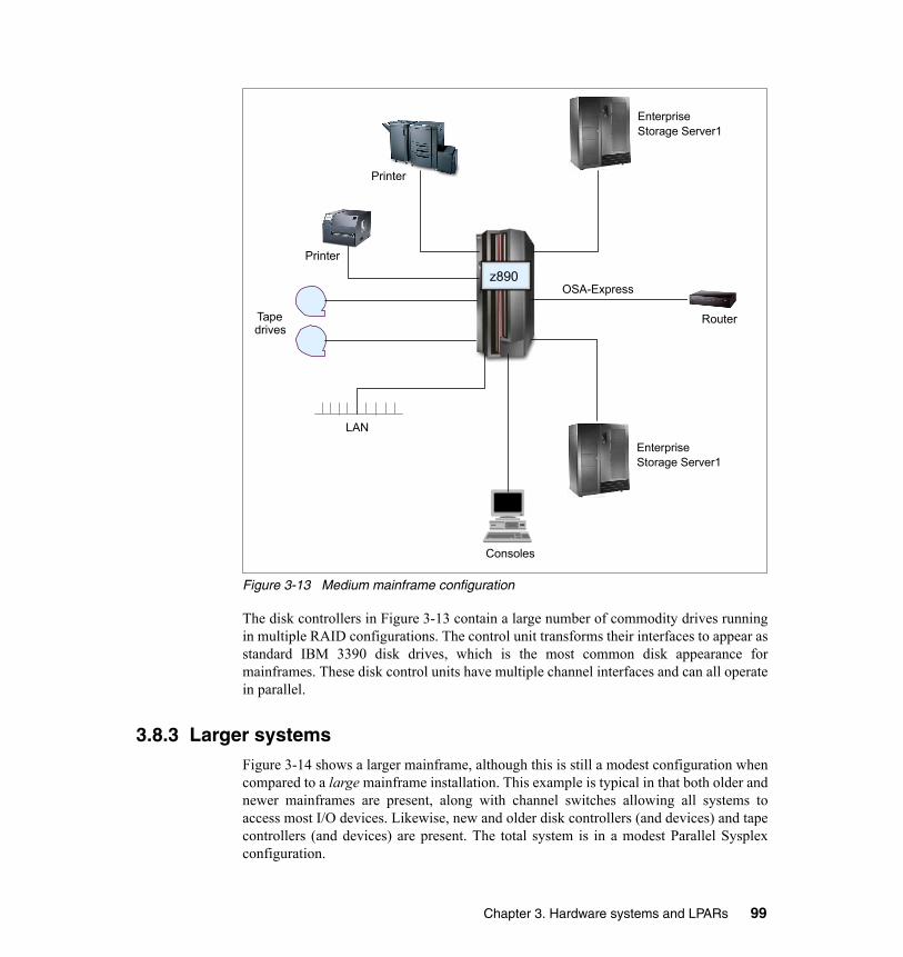
Figure 3-13 Medium mainframe configuration
The disk controllers in Figure 3-13 contain a large number of commodity drives runningin multiple RAID configurations. The control unit transforms their interfaces to appear asstandard IBM 3390 disk drives, which is the most common disk appearance formainframes. These disk control units have multiple channel interfaces and can all operatein parallel.
3.8.3 Larger systemsFigure 3-14 shows a larger mainframe, although this is still a modest configuration whencompared to a large mainframe installation. This example is typical in that both older andnewer mainframes are present, along with channel switches allowing all systems toaccess most I/O devices. Likewise, new and older disk controllers (and devices) and tapecontrollers (and devices) are present. The total system is in a modest Parallel Sysplexconfiguration.
Printer
RouterTape drives
LAN
Consoles
OSA-Expressz890
Printer
EnterpriseStorage Server1
EnterpriseStorage Server1
Chapter 3. Hardware systems and LPARs 99
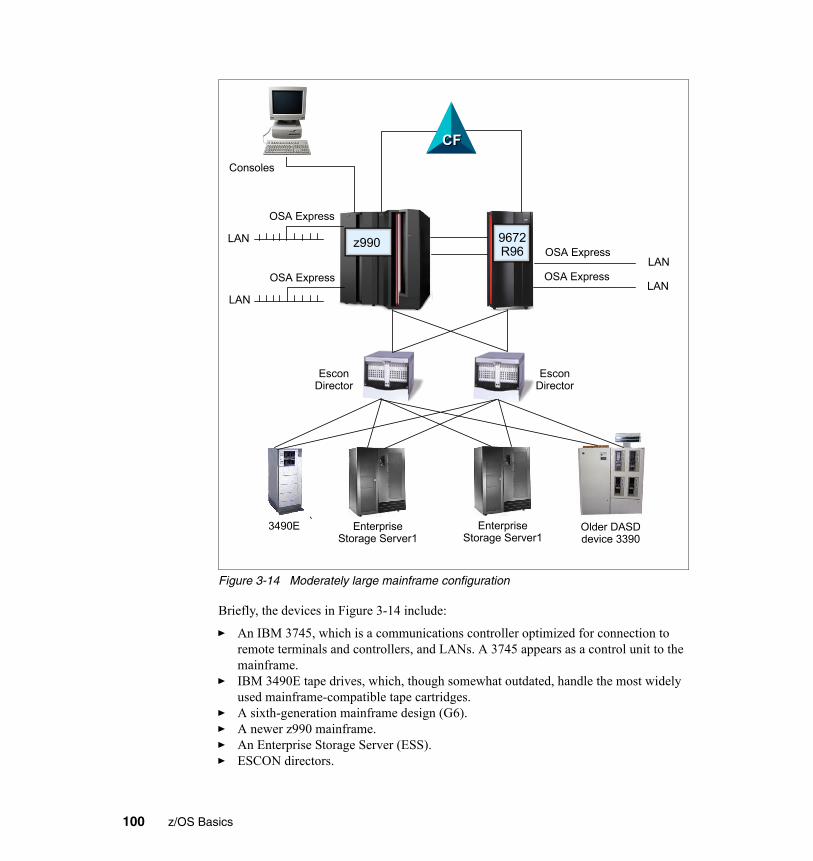
Figure 3-14 Moderately large mainframe configuration
Briefly, the devices in Figure 3-14 include:
� An IBM 3745, which is a communications controller optimized for connection to remote terminals and controllers, and LANs. A 3745 appears as a control unit to the mainframe.
� IBM 3490E tape drives, which, though somewhat outdated, handle the most widely used mainframe-compatible tape cartridges.
� A sixth-generation mainframe design (G6).� A newer z990 mainframe.� An Enterprise Storage Server (ESS).� ESCON directors.
OSA Express
LAN
LAN
Older DASDdevice 3390
3490E
OSA Express
Consoles
CFCF
EsconDirector
EsconDirector
LANOSA Express
LANOSA Express
z990 9672R96
EnterpriseStorage Server1
EnterpriseStorage Server1
100 z/OS Basics
� OSA Express connections to several LANs.� CF (shown as a separate box, but it might be an LPAR in the mainframe).
3.9 SummaryBeing aware of various meanings of the terms systems, processors, CPs, and so forth isimportant for your understanding of mainframe computers. The original S/360architecture, based on CPUs, memory, channels, control units, and devices, and the waythese are addressed, is fundamental to understanding mainframe hardware—even thoughalmost every detail of the original design has been changed in various ways. Theconcepts and terminology of the original design still permeate mainframe descriptionsand designs.
The ability to partition a large system into multiple smaller systems (LPARs) is now acore requirement in practically all mainframe installations. The flexibility of thehardware design, allowing any processor (CP) to access and accept interrupts for anychannel, control unit, and device connected to a given LPAR, contributes to theflexibility, reliability, and performance of the complete system. The availability of a poolof processors (PUs) that can be configured (by IBM) as customer processors (CPs), I/Oprocessors (SAPs), dedicated Linux processors (IFLs), dedicated Java-type processors(zAAPs), and spare processors is unique to mainframes and, again, provides greatflexibility in meeting customer requirements. Some of these requirements are based onthe cost structures of some mainframe software.
In addition to the primary processors just mentioned (the PUs, and all theircharacterizations), mainframes have a network of controllers (special microprocessors)that control the system as a whole. These controllers are not visible to the operatingsystem or application programs.
Since the early 1970s mainframes have been designed as multiprocessor systems, evenwhen only a single processor is installed. All operating system software is designed formultiple processors; a system with a single processor is considered a special case of ageneral multiprocessor design.
All but the smallest mainframe installations typically use clustering techniques, althoughthey do not normally use the terms cluster or clustering. As stated previously, a clusteringtechnique can be as simple as a shared DASD configuration where manual control orplanning is needed to prevent unwanted data overlap.
More common today are configurations that allow sharing of locking and enqueueingcontrols among all systems. Among other benefits, this automatically manages access todata sets so that unwanted concurrent usage does not occur.
Chapter 3. Hardware systems and LPARs 101

The most sophisticated of the clustering techniques is a Parallel Sysplex, which isdiscussed in Chapter 4, “Parallel Sysplex and continuous availability” on page 103.
Key terms in this topic
central electronic complex (CEC)
central processing unit (CPU)
Channel Path Identifier (CHPID)
channel-to-channel (CTC) ESCON channel FICON channel
hardware management console (HMC)
I/O connectivity Integrated Facility for Linux (IFL)
logical partition (LPAR) multiprocessor power-on reset (POR)
Support Element (SE) unicode zAAP processor
102 z/OS Basics

Chapter 4. Parallel Sysplex and continuous availability
4
Objective: In working with the z/OS operating system, you need to understand howit achieves near-continuous availability through technologies such as “no single pointsof failure.”
After completing this topic, you will be able to:� Discuss Parallel Sysplex.� Explain how Parallel Sysplex can achieve continuous availability.� Explain dynamic workload balancing.� Explain the single system image.
© Copyright IBM Corp. 2005, 2006. All rights reserved. 103

4.1 Future of the new mainframeThis course concludes with a discussion of Parallel Sysplex and some examples of howthis powerful technology is used to ensure continuous availability in today’s largesystems environments.
Parallel Sysplex technology allows the linking up to 32 servers with near linearscalability to create a powerful commercial processing clustered system. Every server ina Parallel Sysplex cluster can be configured to share access to data resources, and a“cloned” instance of an application might run on every server.
Parallel Sysplex design characteristics help businesses to run continuously, even duringperiods of dramatic change. Sysplex sites can dynamically add and change systems in asysplex, and configure the systems for no single points of failure.
Through this state-of-the-art cluster technology, multiple z/OS systems can be made towork in concert to more efficiently process the largest commercial workloads.
4.2 What a Parallel Sysplex isA sysplex is a collection of z/OS systems that cooperate, using certain hardware andsoftware products, to process work. It is a clustering technology that can providenear-continuous availability.
A conventional large computer system also uses hardware and software products thatcooperate to process work. A major difference between a sysplex and a conventionallarge computer system is the improved growth potential and level of availability in asysplex. The sysplex increases the number of processing units and z/OS operatingsystems that can cooperate, which in turn increases the amount of work that can beprocessed. To facilitate this cooperation, new products were developed and old productswere enhanced.
A Parallel Sysplex is a sysplex that uses multisystem data-sharing technology. It allowsdirect, concurrent read/write access to shared data from all processing nodes (or servers)in the configuration without impacting performance or data integrity. Each node canconcurrently cache shared data in local processor memory through hardware-assistedcluster-wide serialization and coherency controls.
As a result, work requests that are associated with a single workload, such as businesstransactions or database queries, can be dynamically distributed for parallel execution onnodes in the sysplex cluster based on available processor capacity.
Figure 4-1 shows the visible parts of a Parallel Sysplex, namely the hardware. These arethe key components of Parallel Sysplex as implemented in the hardware architecture.
104 z/OS Basics

Figure 4-1 Sysplex hardware overview
4.2.1 Shared data clusteringParallel Sysplex technology extends the strengths of IBM mainframe computers bylinking up to 32 servers with near linear scalability to create a powerful commercialprocessing clustered system. Every server in a Parallel Sysplex cluster has access to alldata resources, and every “cloned” application can run on every server. Using mainframeCoupling Technology, Parallel Sysplex technology provides a “shared data” clusteringtechnique that permits multi-system data sharing with high performance read/writeintegrity.
This “shared data” (as opposed to “shared nothing”) approach enables workloads to bedynamically balanced across servers in the Parallel Sysplex cluster. It enables criticalbusiness applications to take advantage of the aggregate capacity of multiple servers tohelp ensure maximum system throughput and performance during peak processingperiods. In the event of a hardware or software outage, either planned or unplanned,workloads can be dynamically redirected to available servers, thus providingnear-continuous application availability.
DASDDASDDASDDASDDASDDASD
ESCON / FICON
Sysplex Timer
IBM zSeries
CF02CF
IBM zSeries
CF01CF
z/OS
SysplexLPARs
IBM zSeries
z/OS
SysplexLPARs
12
3
4567
89
1011 12 1
23
4567
89
1011 12
Chapter 4. Parallel Sysplex and continuous availability 105

4.2.2 Non-disruptive maintenanceAnother unique advantage of using Parallel Sysplex technology is the ability to performhardware and software maintenance and installation in a non-disruptive manner.
Through data sharing and dynamic workload management, servers can be dynamicallyremoved from or added to the cluster, allowing installation and maintenance activities tobe performed while the remaining systems continue to process work. Furthermore, byadhering to the IBM software and hardware coexistence policy, software and/or hardwareupgrades can be introduced one system at a time. This capability allows customers to rollchanges through systems at a pace that makes sense for their business.
The ability to perform rolling hardware and software maintenance in a non-disruptivemanner allows business to implement critical business function and react to rapid growthwithout affecting customer availability.
4.3 Continuous availability of mainframesParallel Sysplex technology is an enabling technology, allowing highly reliable,redundant, and robust mainframe technologies to achieve near-continuous availability. Aproperly configured Parallel Sysplex cluster is designed to remain available to its usersand applications with minimal downtime, for example: � Hardware and software components provide for concurrency to facilitate
non-disruptive maintenance, like Capacity Upgrade on Demand, which allows processing or coupling capacity to be added one engine at a time without disruption to running workloads.
� DASD subsystems employ disk mirroring or RAID technologies to help protect against data loss, and exploit technologies to enable point-in-time backup, without the need to shut down applications.
� Networking technologies deliver functions such as VTAM Generic Resources, Multi-Node Persistent Sessions, Virtual IP Addressing, and Sysplex Distributor to provide fault-tolerant network connections.
� I/O subsystems support multiple I/O paths and dynamic switching to prevent loss of data access and improved throughput.
� z/OS software components allow new software releases to coexist with lower levels of those software components to facilitate rolling maintenance.
� Business applications are “data sharing-enabled” and cloned across servers to allow workload balancing to prevent loss of application availability in the event of an outage.
� Operational and recovery processes are fully automated and transparent to users, and reduce or eliminate the need for human intervention.
106 z/OS Basics

Parallel Sysplex is a way of managing this multi-system environment, providing suchbenefits as: � “No single points of failure” on page 107� “Capacity and scaling” on page 108� “Dynamic workload balancing” on page 108� “Ease of use” on page 109� “Single system image” on page 111� “Compatible change and non-disruptive growth” on page 112� “Application compatibility” on page 112� “Disaster recovery” on page 113
These benefits are described in the remaining sections of this topic.
4.3.1 No single points of failureIn a Parallel Sysplex cluster, it is possible to construct a parallel processing environmentwith no single points of failure. Because all of the systems in the Parallel Sysplex canhave concurrent access to all critical applications and data, the loss of a system due toeither hardware or software failure does not necessitate loss of application availability.
Peer instances of a failing subsystem executing on remaining healthy system nodes cantake over recovery responsibility for resources held by the failing instance. Alternatively,the failing subsystem can be automatically restarted on still-healthy systems usingautomatic restart capabilities to perform recovery for work in progress at the time of thefailure. While the failing subsystem instance is unavailable, new work requests can beredirected to other data-sharing instances of the subsystem on other cluster nodes toprovide continuous application availability across the failure and subsequent recovery.This provides the ability to mask planned as well as unplanned outages to the end user.
Because of the redundancy in the configuration, there is a significant reduction in thenumber of single points of failure. Without a Parallel Sysplex, the loss of a server couldseverely impact the performance of an application, as well as introduce systemmanagement difficulties in redistributing the workload or reallocating resources until thefailure is repaired. In an Parallel Sysplex environment, it is possible that the loss of aserver may be transparent to the application, and the server workload can be redistributedautomatically within the Parallel Sysplex with little performance degradation. Therefore,events that otherwise would seriously impact application availability, such as failures inCEC hardware elements or critical operating system components, would, in a ParallelSysplex environment, have reduced impact.
Even though they work together and present a single image, the nodes in a ParallelSysplex cluster remain individual systems, making installation, operation, andmaintenance non-disruptive. The system programmer can introduce changes, such assoftware upgrades, one system at a time, while the remaining systems continue to process
Chapter 4. Parallel Sysplex and continuous availability 107

work. This allows the mainframe IT staff to roll changes through its systems on aschedule that is convenient to the business.
4.3.2 Capacity and scalingThe Parallel Sysplex environment can scale nearly linearly from 2 to 32 systems. Thiscan be a mix of any servers that support the Parallel Sysplex environment. The aggregatecapacity of this configuration meets every processing requirement known today.
4.3.3 Dynamic workload balancing The entire Parallel Sysplex cluster can be viewed as a single logical resource to end usersand business applications. Just as work can be dynamically distributed across theindividual processors within a single SMP server, so too can work be directed to anynode in a Parallel Sysplex cluster having available capacity. This avoids the need topartition data or applications among individual nodes in the cluster or to replicatedatabases across multiple servers.
Workload balancing also permits a business to run diverse applications across a ParallelSysplex cluster while maintaining the response levels critical to a business. Themainframe IT director selects the service level agreements required for each workload,and the workload management (WLM) component of z/OS, along with subsystems suchas CP/SM or IMS, automatically balances tasks across all the resources of the ParallelSysplex cluster to meet these business goals. The work can come from a variety ofsources, such as batch, SNA, TCP/IP, DRDA, or WebSphere MQ.
There are several aspects to consider for recovery. First, when a failure occurs, it isimportant to bypass it by automatically redistributing the workload to utilize theremaining available resources. Secondly, it is necessary to recover the elements of workthat were in progress at the time of the failure. Finally, when the failed element isrepaired, it should be brought back into the configuration as quickly and transparently aspossible to again start processing the workload. Parallel Sysplex technology enables allthis to happen.
Workload distribution After the failing element has been isolated, it is necessary to non-disruptively redirect theworkload to the remaining available resources in the Parallel Sysplex. In the event offailure in the Parallel Sysplex environment, the online transaction workload isautomatically redistributed without operator intervention.
Generic resource management Generic resource management provides the ability to specify to VTAM a commonnetwork interface. This can be used for CICS terminal owning regions (TORs), IMSTransaction Manager, TSO, or DB2 DDF work. If one of the CICS TORs fails, for
108 z/OS Basics

example, only a subset of the network is affected. The affected terminals are able toimmediately log on again and continue processing after being connected to a differentTOR.
4.3.4 Ease of use The Parallel Sysplex solution satisfies a major customer requirement for continuous24-hour-a-day, 7-day-a-week availability, while providing techniques for achievingsimplified Systems Management consistent with this requirement. Some of the featuresof the Parallel Sysplex solution that contribute to increased availability also help toeliminate some Systems Management tasks. Examples include: � “Workload management (WLM) component” on page 109� “Sysplex Failure Manager (SFM)” on page 109� “Automatic Restart Manager (ARM)” on page 110� “Cloning and symbolics” on page 110� “zSeries resource sharing” on page 110
Workload management (WLM) componentThe workload management (WLM) component of z/OS provides sysplex-wide workloadmanagement capabilities based on installation-specified performance goals and thebusiness importance of the workloads. WLM tries to attain the performance goalsthrough dynamic resource distribution. WLM provides the Parallel Sysplex cluster withthe intelligence to determine where work needs to be processed and in what priority. Thepriority is based on the customer's business goals and is managed by sysplex technology.
Sysplex Failure Manager (SFM)The Sysplex Failure Management policy allows the installation to specify failuredetection intervals and recovery actions to be initiated in the event of the failure of asystem in the sysplex.
Without SFM, when one of the systems in the Parallel Sysplex fails, the operator isnotified and prompted to take some recovery action. The operator may choose topartition the non-responding system from the Parallel Sysplex, or to take some action totry to recover the system. This period of operator intervention might tie up critical systemresources required by the remaining active systems. Sysplex Failure Manager allows theinstallation to code a policy to define the recovery actions to be initiated when specifictypes of problems are detected, such as fencing off the failed image that prevents accessto shared resources, logical partition deactivation, or central storage and expandedstorage acquisition, to be automatically initiated following detection of a Parallel Sysplexfailure.
Chapter 4. Parallel Sysplex and continuous availability 109

Automatic Restart Manager (ARM)Automatic restart manager enables fast recovery of subsystems that might hold criticalresources at the time of failure. If other instances of the subsystem in the Parallel Sysplexneed any of these critical resources, fast recovery will make these resources availablemore quickly. Even though automation packages are used today to restart the subsystemto resolve such deadlocks, ARM can be activated closer to the time of failure.
Automatic Restart Manager reduces operator intervention in the following areas: � Detection of the failure of a critical job or started task � Automatic restart after a started task or job failure
After an ABEND of a job or started task, the job or started task can be restarted withspecific conditions, such as overriding the original JCL or specifying jobdependencies, without relying on the operator.
� Automatic redistribution of work to an appropriate system following a system failure
This removes the time-consuming step of human evaluation of the most appropriatetarget system for restarting work
Cloning and symbolics Cloning refers to replicating the hardware and software configurations across thedifferent physical servers in the Parallel Sysplex. That is, an application that is going totake advantage of parallel processing might have identical instances running on allimages in the Parallel Sysplex. The hardware and software supporting these applicationscould also be configured identically on all systems in the Parallel Sysplex to reduce theamount of work required to define and support the environment.
The concept of symmetry allows new systems to be introduced and enables automaticworkload distribution in the event of failure or when an individual system is scheduledfor maintenance. It also reduces the amount of work required by the system programmerin setting up the environment. Note that symmetry does not preclude the need for systemsto have unique configuration requirements, such as the asymmetric attachment of printersand communications controllers, or asymmetric workloads that do not lend themselves tothe parallel environment.
System symbolics are used to help manage cloning. z/OS provides support for thesubstitution values in startup parameters, JCL, system commands, and started tasks.These values can be used in parameter and procedure specifications to allow uniquesubstitution when dynamically forming a resource name.
zSeries resource sharing A number of base z/OS components have discovered that IBM S/390 Coupling Facilityshared storage provides a medium for sharing component information for the purpose ofmulti-system resource management. This exploitation, called IBM zSeries Resource
110 z/OS Basics

Sharing, enables sharing of physical resources such as files, tape drives, consoles, andcatalogs with improvements in cost, performance and simplified systems management.This is not to be confused with Parallel Sysplex data sharing by the database subsystems.zSeries Resource Sharing delivers immediate value even for customers who are notleveraging data sharing, through native system exploitation delivered with the base z/OSsoftware stack.
One of the goals of the Parallel Sysplex solution is to provide simplified systemsmanagement by reducing complexity in managing, operating, and servicing a ParallelSysplex, without requiring an increase in the number of support staff and withoutreducing availability.
4.3.5 Single system image Even though there could be multiple servers and z/OS images in the Parallel Sysplex anda mix of different technologies, the collection of systems in the Parallel Sysplex shouldappear as a single entity to the operator, the end user, the database administrator, and soon. A single system image brings reduced complexity from both operational anddefinition perspectives.
Regardless of the number of system images and the complexity of the underlyinghardware, the Parallel Sysplex solution provides for a single system image from severalperspectives: � Data access, allowing dynamic workload balancing and improved availability � Dynamic Transaction Routing, providing dynamic workload balancing and improved
availability � End-user interface, allowing logon to a logical network entity � Operational interfaces, allowing easier Systems Management
Single point of control It is a requirement that the collection of systems in the Parallel Sysplex can be managedfrom a logical single point of control. The term “single point of control” means the abilityto access whatever interfaces are required for the task in question, without reliance on aphysical piece of hardware. For example, in a Parallel Sysplex of many systems, it isnecessary to be able to direct commands or operations to any system in the ParallelSysplex, without the necessity for a console or control point to be physically attached toevery system in the Parallel Sysplex.
Persistent single system image across failures Even though individual hardware elements or entire systems in the Parallel Sysplex fail,a single system image must be maintained. This means that, as with the concept of singlepoint of control, the presentation of the single system image is not dependent on aspecific physical element in the configuration. From the end-user point of view, the
Chapter 4. Parallel Sysplex and continuous availability 111

parallel nature of applications in the Parallel Sysplex environment must be transparent.An application should be accessible regardless of which physical z/OS image supports it.
4.3.6 Compatible change and non-disruptive growth A primary goal of Parallel Sysplex is continuous availability. Therefore, it is arequirement that changes such as new applications, software, or hardware can beintroduced non-disruptively, and that they be able to coexist with current levels. Insupport of compatible change, the hardware and software components of the ParallelSysplex solution will allow the coexistence of two levels, that is, level N and level N+1.This means, for example, that no IBM software product will make a change that cannotbe tolerated by the previous release.
4.3.7 Application compatibilityA design goal of Parallel Sysplex clustering is that no application changes be required totake advantage of the technology. For the most part, this has held true, although someaffinities need to be investigated to get the maximum advantage from the configuration.
From the application architects’ point of view, three major points might lead to thedecision to run an application in a Parallel Sysplex:� Technology benefits
Scalability (even with non-disruptive upgrades), availability, and dynamic workloadmanagement are tools that enable an architect to meet customer needs in cases wherethe application plays a key role in the customer’s business process. With themultisystem data sharing technology, all processing nodes in a Parallel Sysplex havefull concurrent read/write access to shared data without affecting integrity andperformance.
� Integration benefits
Since many applications are historically S/390- and z/OS-based, new applications onz/OS get performance and maintenance benefits, especially if they are connected toexisting applications.
� Infrastructure benefits
If there is already an existing Parallel Sysplex, it needs very little infrastructure workto integrate a new application. In many cases the installation does not need tointegrate new servers. Instead it can leverage the existing infrastructure and make useof the strengths of the existing sysplex. With Geographically Dispersed ParallelSysplex™ (GDPS®)—connecting multiple sysplexes in different locations—themainframe IT staff can create a configuration that is enabled for disaster recovery.
112 z/OS Basics

4.3.8 Disaster recoveryGeographically Dispersed Parallel Sysplex (GDPS) is the primary disaster recovery andcontinuous availability solution for a mainframe-based multi-site enterprise. GDPSautomatically mirrors critical data and efficiently balances workload between the sites.
GDPS also uses automation and Parallel Sysplex technology to help manage multi-sitedatabases, processors, network resources and storage subsystem mirroring. Thistechnology offers continuous availability, efficient workload management, resourcemanagement and prompt data recovery for business-critical mainframe applications anddata. With GDPS, the current maximum distance between the two sites is 100km (about62 miles) of fiber, although there are some other restrictions. This provides asynchronous solution that helps to ensure no loss of data.
There is also GDPS/XRC, which can be used over extended distances and should providea recovery point objective of less than two minutes (that is, a maximum of two minutes ofdata would need to be recovered or is lost).
4.4 Summary Parallel Sysplex technology allows the linking up to 32 servers with near linearscalability to create a powerful commercial processing clustered system. Every server ina Parallel Sysplex cluster has access to all data resources, and every “cloned” applicationcan run on every server. When used with coupling technology, Parallel Sysplex providesa “shared data” clustering technique that permits multi-system data sharing with highperformance read/write integrity.
Sysplex design characteristics help businesses to run continuously, even during periodsof dramatic change. Sysplex sites can dynamically add and change systems in a sysplex,and configure the systems for no single points of failure.
Through this state-of-the-art cluster technology, multiple z/OS systems can be made towork in concert to more efficiently process the largest commercial workloads.
Key terms in this topic
Automatic Restart Manager (ARM)
cloning continuous availability
coupling technology dynamic workload management
Geographically Dispersed Parallel Sysplex (GDPS)
Parallel Sysplex shared data clustering single point of control
symbolics sysplex zSeries resource sharing
Chapter 4. Parallel Sysplex and continuous availability 113

114 z/OS Basics


![Oracle Fusion Middleware Programming JDBC for Oracle ... · [1]Oracle® Fusion Middleware Developing JDBC Applications for Oracle WebLogic Server 12.1.3 12c (12.1.3) E41865-04 August](https://static.fdocuments.us/doc/165x107/5f7d022cb5de2a3c13288475/oracle-fusion-middleware-programming-jdbc-for-oracle-1oracle-fusion-middleware.jpg)