Part 1: Operating Instructions Cl. 550-12-12 - Duerkopp Adler · Part 1: Operating Instructions Cl....
15
Contents Page: Preface and General Safety Notes Part 1: Operating Instructions Cl. 550-12-12 1. Product Description 1.1 Short Description and Proper Use . . . . . . . . . . . . . . . . . . . . . . . . . . . . . . . . . . 5 1.2 Optional Equipment . . . . . . . . . . . . . . . . . . . . . . . . . . . . . . . . . . . . . . . . . . 5 1.3 Technical Specification . . . . . . . . . . . . . . . . . . . . . . . . . . . . . . . . . . . . . . . . 6 2. Operation 2.1 Threading the Needle Thread (Upper Thread) . . . . . . . . . . . . . . . . . . . . . . . . . . . 6 2.2 Threading the Hook Thread (Lower Thread) . . . . . . . . . . . . . . . . . . . . . . . . . . . . . 6 2.3 Thread Tension . . . . . . . . . . . . . . . . . . . . . . . . . . . . . . . . . . . . . . . . . . . . . 8 2.4 Upper Thread Quantity for Sure Stitch Formation . . . . . . . . . . . . . . . . . . . . . . . . . . 8 2.5 Optional Equipment reinforcing . . . . . . . . . . . . . . . . . . . . . . . . . . . . . . . . . . . . 10 2.5.1 General . . . . . . . . . . . . . . . . . . . . . . . . . . . . . . . . . . . . . . . . . . . . . . . . . 10 2.5.2 Optional Equipment . . . . . . . . . . . . . . . . . . . . . . . . . . . . . . . . . . . . . . . . . . 10 2.5.3 Operating Elements . . . . . . . . . . . . . . . . . . . . . . . . . . . . . . . . . . . . . . . . . . 11 2.5.4 Loading the reinforcement tape . . . . . . . . . . . . . . . . . . . . . . . . . . . . . . . . . . . . 12 2.5.5 Adjustments on the tape unwinder . . . . . . . . . . . . . . . . . . . . . . . . . . . . . . . . . . 12 2.5.6 Replacing the presser foot . . . . . . . . . . . . . . . . . . . . . . . . . . . . . . . . . . . . . . 14 3. Maintenance 3.1 Cleaning . . . . . . . . . . . . . . . . . . . . . . . . . . . . . . . . . . . . . . . . . . . . . . . . 15 3.2 Lubricating . . . . . . . . . . . . . . . . . . . . . . . . . . . . . . . . . . . . . . . . . . . . . . . 16
Transcript of Part 1: Operating Instructions Cl. 550-12-12 - Duerkopp Adler · Part 1: Operating Instructions Cl....

Contents Page:
Preface and General Safety Notes
Part 1: Operating Instructions Cl. 550-12-12
1. Product Description
1.1 Short Description and Proper Use . . . . . . . . . . . . . . . . . . . . . . . . . . . . . . . . . . 5
1.2 Optional Equipment . . . . . . . . . . . . . . . . . . . . . . . . . . . . . . . . . . . . . . . . . . 5
1.3 Technical Specification . . . . . . . . . . . . . . . . . . . . . . . . . . . . . . . . . . . . . . . . 6
2. Operation
2.1 Threading the Needle Thread (Upper Thread) . . . . . . . . . . . . . . . . . . . . . . . . . . . 6
2.2 Threading the Hook Thread (Lower Thread) . . . . . . . . . . . . . . . . . . . . . . . . . . . . . 6
2.3 Thread Tension . . . . . . . . . . . . . . . . . . . . . . . . . . . . . . . . . . . . . . . . . . . . . 8
2.4 Upper Thread Quantity for Sure Stitch Formation . . . . . . . . . . . . . . . . . . . . . . . . . . 8
2.5 Optional Equipment reinforcing . . . . . . . . . . . . . . . . . . . . . . . . . . . . . . . . . . . . 10
2.5.1 General . . . . . . . . . . . . . . . . . . . . . . . . . . . . . . . . . . . . . . . . . . . . . . . . . 10
2.5.2 Optional Equipment . . . . . . . . . . . . . . . . . . . . . . . . . . . . . . . . . . . . . . . . . . 10
2.5.3 Operating Elements . . . . . . . . . . . . . . . . . . . . . . . . . . . . . . . . . . . . . . . . . . 11
2.5.4 Loading the reinforcement tape . . . . . . . . . . . . . . . . . . . . . . . . . . . . . . . . . . . . 12
2.5.5 Adjustments on the tape unwinder . . . . . . . . . . . . . . . . . . . . . . . . . . . . . . . . . . 12
2.5.6 Replacing the presser foot . . . . . . . . . . . . . . . . . . . . . . . . . . . . . . . . . . . . . . 14
3. Maintenance
3.1 Cleaning . . . . . . . . . . . . . . . . . . . . . . . . . . . . . . . . . . . . . . . . . . . . . . . . 15
3.2 Lubricating . . . . . . . . . . . . . . . . . . . . . . . . . . . . . . . . . . . . . . . . . . . . . . . 16


1. Product Description
1.1 Short Description and Proper Use
The DÜRKOPP ADLER 550-12-12 is a configured sewing station forthe programmed advance crimping of shoulders and sewing on of thesleeve joining.With the appropriate optional equipment it can also be used forselvedges on armholes, neckholes, etc.
• The sewing station is equipped with a single needle-double chainstitch sewing machine with differential bottom transport and footupper transport.
• The upper transport and forward feed dog of the differential bottomtransport work synchronized. They can be set and switcheddifferent to the rear feed dog.
• Electro-pneumatic thread trimmer for upper and lower thread.
• Pressure foot stroke and stitch condensation at seam beginningand seam end.
• A microprocessor control assumes the automatic multi-widthregulation with programable follow-up switching.
• The memory capacity of the controls allows the pre-programmingof 20 sewing programs including the complete graduated size sets.Each sewing program can contain up to 13 steps per seam run.Each step can have its own designated crimp value.
• Mirroring left-right sewing piece via the push of a button.
• Very simple programming via an operating terminal with graphicmonitor. The operating surface of the monitor can be called up in10 languages by pushing a button.
• With a memory card program transfer to other sewing stations, aswell as program retention, can occur.
Proper Use !
The DÜRKOPP ADLER 550-12-12 may only be used for the advancecrimping of shoulders, the sewing on of sleeve joinings and, with theappropriate optional equipment, for selvedge work with materials oftextile fibers and leather.
1.2 Optional Equipment
If the DÜRKOPP ADLER 550-12-12 is to be used for bordering ofarmholes, neckholes, etc., then is must be equipped with the optionalequipment listed in chapter 2.5.2.
5

1.3 Technical Specification
Machine head: Class 935 - 940 - 6
Needle system: 934 SINNeedle thickness: Nm 90Threads: As needle and hook thread spun monofilament
sewing yarns
Stitch type: 401 double chain stitch Number of stitches: 3200 / min (recommended number of stitches
ex works)Stitch length: 2.5 mm for rear feed dog (fixed setting)
Transport length for forward feed dog andtransport foot adjustable up to 6 mm
Stitch condensation: 1.5 mm
Operating pressure: 6 barAir consumption: approx. 0.5 NL per work cycle
Nominal voltage: 1 x 220 - 240 V, 50 / 60 Hz
Dimensions: (H x W x D) 1600 x 1530 x 951 mm
2. Operation
2.1 Threading the Needle Thread (Upper thread)
Caution Risk of Injury !
Turn main switch off.Thread the upper thread only with the machine switched off.
– Place the thread spool 1 on the thread stand.– Guide the thread as shown through the holes and tension discs in
the thread guide plate.– Guide the thread in order through guide plate 3, thread guide 4,
thread tension 8, thread guide 6 and thread drawing plate 7.– Guide the thread through thread guide 13 and thread drawing lever
12.– Guide the thread through pre-tension 9, thread guide 10 and
needle eye. Cut off the excess thread end.
2.2 Threading the Hook Thread (Lower Thread)
Caution Risk of Injury !
Turn main switch off.Thread the lower thread only with the machine switched off.
– Place the thread spool 2 on the thread stand.– Guide the thread as shown through the holes and tension discs in
the thread guide plate.– Guide the thread in order through the guide plate 3, thread guide
4, thread tension 5 and lower thread guide 19.– Feed the thread through the slot (see arrow) in the thread gutter 18.– Remove cover plate 11 and swing holder 14 up out of its catch.
Guide the thread through thread guides 15 and thread drawinghook 16.Swing holder 14 back and allow to catch.
– Pull the thread through the hook 17 with a tweezers and pull tight.Insert cover plate 11 again.
6

3
4
5
6 7 8
9
10
11
12 13
14
15
16
17 18 19
1 2
7

2.3 Thread Tension
The tension of the needle thread (upper thread) must be greater thanthat of the hook thread (lower thread).
Too great thread tensions cause a puckering of the material. A too lowhook thread tension leads to missing stitches.
– Set the needle thread tension with the knurled screw 1.– Set the hook thread tension with the knurled screw 2.
2.4 Upper Thread Quantity for Sure Stitch Formation
With elastic sewing yarns (e.g. synthetic fiber yarns or monofilamentyarns) a certain upper thread quantity must be drawn off for assuredstitch formation .
Elastic sewing threads: Non-elastic sewing threads:
1
2
3
4
5
3
4
5
8

Caution Risk of Injury !
Turn main switch off.Set the thread regulator only with the machine switched off.
Elastic sewing threads :– Turn the handwheel until the thread drawing lever 5 is in its lowest
position.– Loosen screws 3.– Set the thread regulator 4.
The thread hole in the thread drawing lever 5 must be visiblebelow the thread regulator 4.
– Tighten screws 3 again.– Guide the needle thread down over the forward bow of the thread
regulator 4.
Non-elastic sewing threads (e.g. cotton):– Turn the handwheel until the thread drawing lever 5 is in its lowest
position.– Loosen screws 3.– Set the thread regulator.
The thread hole in the thread drawing lover 5 must be visibleabove the thread regulator 4.
– Tighten screws 3 again.– Guide the needle thread down in front of the forward bow of the
thread regulator 4.
9
2.5 Optional Equipment reinforcing
2.5.1 GeneralWith the optional reinforcing equipment the cut edge of the materialis secured (reinforced) by attaching tape .
The tape feeder automatically feeds the reinforcement tape duringsewing.The tape unwinder enables tension-free attaching of the reinforcementtape.
After a programmed number of stitches the tape scissors cut thereinforcement tape within the seam.Thus, the reinforcement tape does not jut out at the material edges.
Exchangeable presser feet enable the use of 3 different reinforcementtape widths.
Reinforcing can be performed either during automatic operation ormanual operation.
2.5.2 Optional equipmentZ129 3202Tape unwinder for tension-free feeding of reinforcement ta-
pes
Z129 3002Tape feeder and cutter for automatic feeding and cutting thereinforcement tape
940 10010Feeding foot specifically for reinforcing operations
Depending on the tape width:
940 10002Presser foot with guide worm for 1.5-mm-wide reinforce-ment tape
940 10022Presser foot with guide worm for 2-mm-wide reinforcementtape
940 10042Presser foot with guide worm for 3-mm-wide reinforcementtapeThis also requires:
940 10050Tape guide at the tape feeder for 3-mm-wide reinforcementtape
10
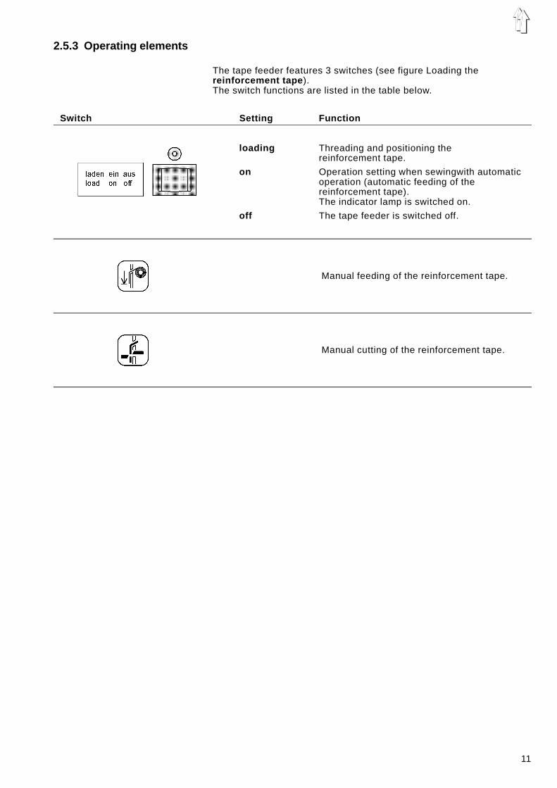
2.5.3 Operating elements
The tape feeder features 3 switches (see figure Loading thereinforcement tape ).The switch functions are listed in the table below.
Switch Setting Function
loading Threading and positioning thereinforcement tape.
on Operation setting when sewingwith automaticoperation (automatic feeding of thereinforcement tape).The indicator lamp is switched on.
off The tape feeder is switched off.
Manual feeding of the reinforcement tape.
Manual cutting of the reinforcement tape.
11

2.5.4 Loading the reinforcement tape
– Load the reinforcement tape as shown in the figure Loading thereinforcement tape .While loading make sure not to twist the reinforcement tape.
– Set the switch A at "loading ".– Introduce the reinforcement tape into guide B .
The reinforcement tape is transported via the guide into thefunnel C.
– Pull the reinforcement tape upward out of the funnel C using a pairof tweezers.
– Set the switch A at "on " (centre position).The reinforcement tape is automatically cut and clamped abovethe funnel.It is now in its feeding position.
ATTENTION !Always be sure to remove the cut pieces of the reinforcement tapefrom the funnel.If the cut pieces are not removed, they will hinder the automaticfeeding of the reinforcement tape !Remove the cut pieces using a pair of tweezers or by sewing with airjet.
– The tape feeder is ready for sewing.
2.5.5 Adjustments on the tape unwinder
The tape unwinder enables tension-free attaching of the reinforcementtape.The tape unwinder rollers draw a defined length of reinforcement tapefrom the tape roll. This drawn reinforcement tape is then attached.
The speed and feeding period of the tape unwinder rollers mustbe adjusted to each other such that even at maximum sewingspeed and with maximum seam length the reinforcement tape isnever drawn directly from the tape roll.
Adjusting elements
Two potentiometers are at the tape unwinder (see figure Loading thereinforcement tape ).
Potentiometer Function
Setting the speed
Setting the fee-ding period
The potentiometer serves to setthe speed of the tape unwinderrollers.
The potentiometer serves to setthe feeding period (operating period) of the tape unwinderrollers.
12
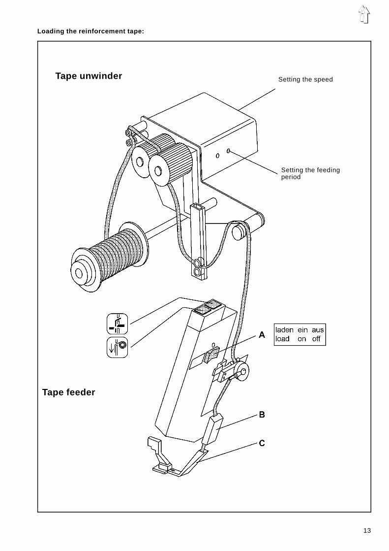
Loading the reinforcement tape:
Tape unwinder
Tape feeder
Setting the feedingperiod
Setting the speed
13
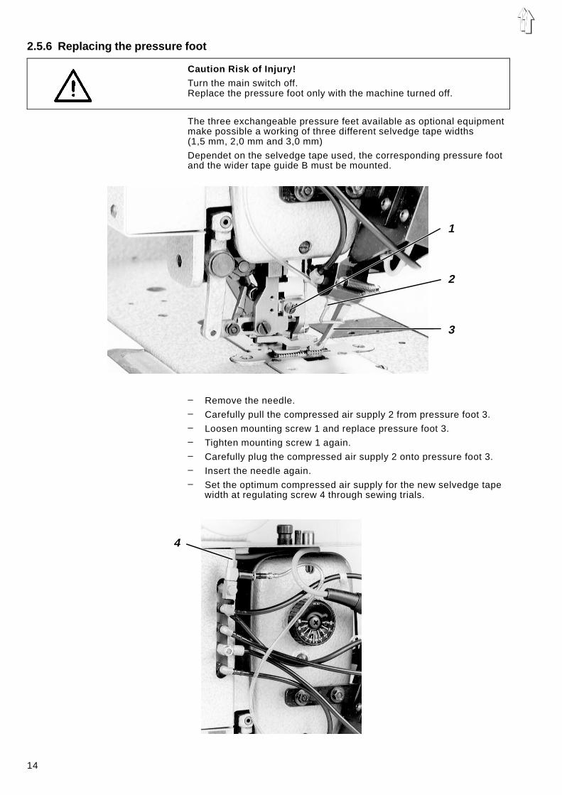
2.5.6 Replacing the pressure foot
Caution Risk of Injury!
Turn the main switch off.Replace the pressure foot only with the machine turned off.
The three exchangeable pressure feet available as optional equipmentmake possible a working of three different selvedge tape widths(1,5 mm, 2,0 mm and 3,0 mm)
Dependet on the selvedge tape used, the corresponding pressure footand the wider tape guide B must be mounted.
– Remove the needle.– Carefully pull the compressed air supply 2 from pressure foot 3.– Loosen mounting screw 1 and replace pressure foot 3.– Tighten mounting screw 1 again.– Carefully plug the compressed air supply 2 onto pressure foot 3.– Insert the needle again.– Set the optimum compressed air supply for the new selvedge tape
width at regulating screw 4 through sewing trials.
1
2
3
4
14
3. Maintenance
Caution Risk of Injury !
Turn main switch off.Maintenance of the sewing unit may only be conducted when it isswitched off.
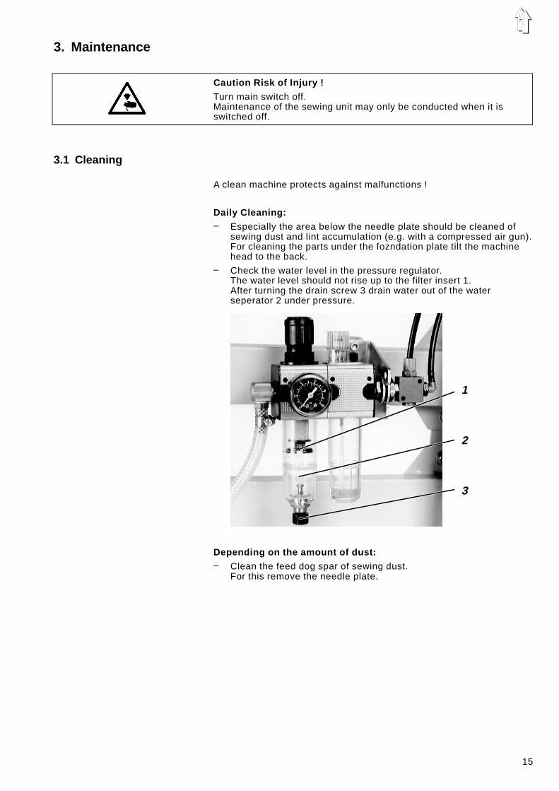
3.1 Cleaning
A clean machine protects against malfunctions !
Daily Cleaning:– Especially the area below the needle plate should be cleaned of
sewing dust and lint accumulation (e.g. with a compressed air gun).For cleaning the parts under the fozndation plate tilt the machinehead to the back.
– Check the water level in the pressure regulator.The water level should not rise up to the filter insert 1.After turning the drain screw 3 drain water out of the waterseperator 2 under pressure.
Depending on the amount of dust:– Clean the feed dog spar of sewing dust.
For this remove the needle plate.
1
2
3
15

3.2 Lubricating
For lubricating the machine use only ESSO SP-NK 10 lubricating oil.SP-NK 10 is available from the DÜRKOPP ADLER AG sales offices.
Checking the oil level in the hook drive housing– The oil level in the hook drive housing 2 should not fall below the
lower, long marking line on the viewing glass when the machine istilted to the back.
– If necessary, fill oil to the upper marking line.For this screw out the oil fill screw 1.
Checking the oil level in the reservoir
The reservoir 3 supplies all bearing positions of the machine exceptfor the hook drive via a central oil wick lubrication.– The oil level in the reservoir 3 should not fall below the "Min" mark
with the machine head upright.– If necessary, fill oil through the holes in the viewing glass up to the
"Max" mark.
1
2
3
16

Checking the oil level in the oil reservoir of the maintenance unit– The oil level in oil reservoir 5 should not drop below the groove
marking.– If necessary, fill oil up to the groove marking.– For this completely shut off the compressed air by turning the knob
1 to the left.– To fill screw out the oil fill screw 3.– After filling with oil set an operating pressure of 6 bar by pulling up
the knob 1 and turning it to the right.The set operating pressure can be seen on the pressure gauge 4.
Checking the oil flow of the oil mister– Under operating pressure a drop of oil should drip out of the tube
under viewing glass 5 after about 10 work cycles.– Regulate the strength of the thus created oil mist with the setting
screw 2.
1
2
3
4
5
17