Parametric Robot Control · 243 Fig. 1 1 Introduction The rapid development of CAAD software in the...
10
242 INTEGRATION THROUGH COMPUTATION ACADIA 2011 _PROCEEDINGS AC C AC CA A D A AD DI D IA A A A A 2 2 2 2 2 2 2 0 20 0 0 DIA 2 DIA CA A AC 2 20 A CA A Robots are gaining popularity in architecture. Snøhetta has recently purchased their own industrial robot, becoming one of the first architectural offices to adopt robot technology. As more and more architects are exposed to robotic fabrication, the need for easy interoperability, integration into architectural design tools and general accessibility will increase. Architects are discovering that industrial robots are much more than kinematic machines for stacking bricks, welding or milling - they are highly multifunctional and can be used for a huge variety of tasks. However, industry standard software does not provide easy solutions for allowing direct robot control right from CAAD (Computer Aided Architectural Design) systems. In this paper we will discuss existing methods of programming industrial robots, published architectural results (Gramazio and Kohler 2008) and the design of a new user interface that allows intuitive control of parametric designs and customized robotic mass production, by integrating CAM (Computer Aided Manufacturing) functions into CAAD. Keywords: robot programming, parametric design, mass customization, grasshopper component design, fabrication, robot milling, digital architecture Parametric Robot Control INTEGRATED CAD/CAM FOR ARCHITECTURAL DESIGN Johannes Braumann Vienna University of Technology Sigrid Brell-Cokcan Vienna University of Technology ABSTRACT
Transcript of Parametric Robot Control · 243 Fig. 1 1 Introduction The rapid development of CAAD software in the...
242
INTEGRATION THROUGH COMPUTATIONACADIA 2011 _PROCEEDINGSACCACCAADAADDIDIAAAAA 222222202000DIA 2DIACAAAC 220ACAA
Robo ts a re ga i n i ng popu l a r i t y i n a r ch i t ec tu re . Snøhe t t a has r ecen t l y pu rchased
t he i r own i ndus t r i a l r obo t , becom ing one o f t he f i r s t a r ch i t ec tu r a l o f f i ces t o adop t
r obo t t echno logy. As mo re and mo re a rch i t ec t s a re exposed to r obo t i c f ab r i ca t i on ,
t he need f o r easy i n t e rope rab i l i t y, i n t eg ra t i on i n t o a rch i t ec tu r a l des i gn t oo l s and
gene ra l access ib i l i t y w i l l i nc rease . A rch i t ec t s a re d i scove r i ng t ha t i ndus t r i a l
r obo t s a re much mo re t han k i nema t i c mach i nes f o r s t ack i ng b r i c ks , we ld i ng o r
m i l l i ng - t hey a re h i gh l y mu l t i f unc t i ona l and can be used f o r a huge va r i e t y o f
t asks . Howeve r, i ndus t r y s t anda rd so f twa re does no t p rov i de easy so l u t i ons
f o r a l l ow ing d i r ec t r obo t con t r o l r i gh t f r om CAAD (Compu te r A ided A rch i t ec tu r a l
Des i gn ) s ys tems . I n t h i s pape r we w i l l d i scuss ex i s t i ng me thods o f p rog ramming
i ndus t r i a l r obo t s , pub l i shed a rch i t ec tu r a l r esu l t s (G ramaz io and Koh l e r 2008 ) and
t he des i gn o f a new use r i n t e r f ace t ha t a l l ows i n t u i t i v e con t r o l o f pa rame t r i c
des i gns and cus tom i zed robo t i c mass p roduc t i on , by i n t eg ra t i ng CAM (Compu te r
A ided Manu fac tu r i ng ) f unc t i ons i n t o CAAD.
Keywo rds : r obo t p rog ramming , pa rame t r i c des i gn , mass cus tom i za t i on ,
g r asshoppe r componen t des i gn , f ab r i ca t i on , r obo t m i l l i ng , d i g i t a l a r ch i t ec tu re
Parametric Robot ControlINTEGRATED CAD/CAM FOR ARCHITECTURAL DESIGN
Johannes Braumann
V ienna Un i ve r s i t y o f Techno logy
Sig r id B re l l -Cokcan
V ienna Un i ve r s i t y o f Techno logy
ABSTRACT

243
Fig. 1
1 Introduct ion
The rap id deve lopment of CAAD sof tware in the last few decades a l lows arch i tectura l
forms to be parametr ica l ly cont ro l led (F igure 1) , resu l t ing in automat ic generat ion
of des ign var iants or overa l l des ign management (Eastman et a l . 2008). Rea l iz ing
parametr ic des igns requi res f lex ib le processes that can fabr icate h igh vo lumes at
reasonably low costs, re fer red to as mass customizat ion (P i l le r 2004; Ramani et a l .
2004).
Arch i tects want to cont ro l the const ruct ion and fabr icat ion process of the i r own
des igns, the machin ic process ing (Gramaz io & Kohler, Menges, Scheurer in Kolarev ic
2008; Iwamoto 2009). One problem ar ises as soon as (parametr ic ) f reeform des igns
are to be mater ia l i zed: arch i tects do not have appropr ia te sof tware to cont ro l the very
end of the overa l l des ign process: fabr icat ion . Leading CAAD deve lopers have so
far not prov ided adequate so lut ions for d i rect ly l ink ing d i f ferent types of machines to
CAD systems. The bu i ld ing indust r y invo lved in f reeform arch i tecture has overcome
th is def ic i t by deve lop ing the i r own “ in-house” custom-made sof tware too ls. Therefore
h igh-end geometry and fabr icat ion consul t ing in arch i tecture is rap id ly becoming a new
specia l i zed core bus iness run by computer sc ient is ts and mathemat ic ians ( re fer to
companies such as Evo lute (E igensatz et a l . 2010) or des ign-to-product ion (Scheurer
2010) ) . In our prev ious research we have shown the advantages of product ion- immanent
des ign and rea l t ime feedback to eva luate not on ly the des ign of a parametr ic ob ject ,
but a lso i ts manufactur ing re la ted proper t ies (Bre l l -Cokcan and Braumann 2010).
In th is paper we propose the use of a graphica l a lgor i thm edi tor as a new inter face
for an indust r ia l robot . The resu l t is user-customized CAAD sof tware where machine
const ra in ts are inc luded as addi t iona l des ign parameters d i rect ly generat ing robot
cont ro l data f i les, to be used for mass customizat ion.
2 Exist ing Methods for Programming a KUKA Robot
In genera l , there are two d is t inct ive st ra teg ies for programming indust r ia l robots: Onl ine/
automat ic (F igure 2) and of f l ine/manual programming (F igure 3) (B iggs and MacDonald
2003). Onl ine programming is used most ly for indust r ia l appl icat ions such as loading
and weld ing, where points are “ taught” ind iv idua l ly v ia the KCP (KUKA Contro l Panel )
or in the v i r tua l robot env i ronment KUKA SimPro. In the f ie ld of arch i tecture, where the
d ig i ta l CAD/CAM workf low is important , on l ine programming is rare ly used.
2.1 ROBOT OFFLINE PROGRAMMING
Robot of f l ine programming is per formed at an externa l computer outs ide the robot ic ce l l
and is s imi la r to the t rad i t iona l way of work ing wi th CNC (Computer Numer ic Contro l )
machines, ( i .e . , mov ing data f rom CAD to CAM sof tware) and then as NC (Numer ic
Contro l ) code, a lso known as G-Code, to a CNC mi l l ing machine. Addi t iona l ly, robot
mi l l ing requi res the use of a k inemat ic post-processor/s imulator, in our case KUKA
SimPro/CAMRob. Th is resu l ts in a d ig i ta l workf low invo lv ing at least three sof tware
too ls by d i f ferent deve lopers. “Rea l t ime” des ign and product ion feedback that a l lows
an eva luat ion of the fabr icat ion proper t ies throughout the workf low is miss ing.
Prev ious research shows the poss ib i l i ty o f s t reaml in ing the d ig i ta l CAD-CAM-Robot
workf low by us ing parametr ic des ign too ls for robot mi l l ing (Bre l l -Cokcan et a l . 2009).
To fur ther opt imize of f l ine programming for a KUKA robot we wi l l demonst rate in
Sect ion 4 the des ign of the custom KUKA|prc (parametr ic robot cont ro l ) component
wi th in Grasshopper, a parametr ic des ign p lug- in for the CAD sof tware Rhinoceros.
2.2 KUKA ROBOT LANGUAGE CODE
The KUKA Robot Language (KRL) is a proprietary programming language with similarities to
Pascal and is used to control KUKA robots. Unlike G-Code, it does not contain just tool and
machine movement commands, but can also declare variables and work with conditional
clauses. While the KRL documentation (KUKA Robotics 2003) explains a set of commands, it
does not provide detailed information on the required structure of a proper control data file in
Fig. 3
Fig. 2
Figure 1. Spencer Dock Bridge: Parametric
freeform design, CNC-milled formwork - Image
courtesy of Nedcam
Figure 2. Online programming via KUKA Sim Pro
(left) or via the KUKA Control Panel (right)
Figure 3. Existing offline data workflow from CAD to
an industrial robot
INTERFACE AND IMMERSION

244
INTEGRATION THROUGH COMPUTATIONACADIA 2011 _PROCEEDINGS
KRL (Mühe et al. 2010). We therefore had to reverse-engineer the structure of KRL files created
by the kinematics postprocessor KUKA SimPro/CAMRob. Basically, a Numeric Control fi le for
KUKA consists of two separate files: A *.dat fi le where variables such as the home position
are stored and a *.src fi le which contains the various commands, like movement commands,
loops, sensor queries et cetera. There are various ways of giving movement commands to a
robot, the most common ones are the following (Takase et al. 1981):
Joint coordinate programming consists of absolute axis rotation commands, instructing the
robot to move each of its six axes to a defined rotation value.
A1 0, A2 10, A3 90, A4 20, A5 60, A6 25
Cartesian coordinate programming defines the location and orientation of the end-effector
in a previously defined Cartesian coordinate system. This can either be point-to-point (PTP)
commands where the end-effector moves from one position to the next with the least amount
of axis rotation or linear (LIN) commands where the end-effector moves from one position to
the next along a straight line.
X 10, Y 20, Z 40, A 45, B 75, C 15
3 Parametr ic Robot Programming for Architectural Design
Understanding the robot’s data processing described in Section 2, it appears feasible to
create KRL code via custom scripting (offl ine programming), thereby automating the fabrication
process for architectural mass customization.
For most architectural purposes, the location of the tool has to be precisely controlled,
therefore requi r ing the use of Cartes ian coord inate programming . The k inemat ics of the
robot do not necessar i l y have to be s imulated in the parametr ic model ing env i ronment,
as they are so lved accord ing to the end-ef fector pos i t ion/or ientat ion in rea l t ime when
the KRL code is executed at the cont ro l un i t . However, s imulat ing the robot ’s k inemat ics
in a des ign env i ronment enables the des igner to react to reachabi l i ty-const ra in ts or
poss ib le co l l is ions, thereby opt imiz ing the use of the ava i lab le workspace.
3.1 OFFLINE PROGRAMMING VIA CUSTOMIZED SCRIPTING
A recent arch i tectura l example invo lv ing indust r ia l robots and custom scr ipt ing is the
Pike Loop pro ject (F igure 4) by Gramaz io and Kohler (Bär tsch i et a l . 2010), where a
specia l “wigg led bond br ick ar rangement is mapped onto a gener ic double curved
sur face”. Th is resu l ts in a CAD-created sur face be ing processed by a scr ipt that
dea ls wi th the var ious problems invo lved in robot ic br ick stack ing, l ike the genera l
ar rangement, the boundary condi t ions and opt imizat ion issues (F igure 5a) . Whi le the
scr ipt is executed, the user cannot in teract but has to wai t unt i l the scr ipt is f in ished;
the user is then presented wi th the resu l t and has to eva luate i f the ach ieved output
meets predef ined requi rements or i f the resu l t has to be changed. Th is can be done
e i ther by changing the predef ined requi rements, by modi fy ing the in i t ia l CAD geometry,
or by changing the code i tse l f . Bas ica l ly, the code acts as a solver for a sequence of
c lear ly (pre)def ined problems.
Figure 4. Robotic fabrication for the Pike Loop
Project by Gramazio and Kohler
Fig. 4

245
Even though the use of an indust r ia l robot for br ick lay ing is a very innovat ive arch i tectura l
appl icat ion, the publ ished d ig i ta l workf low v ia customized scr ipt ing descr ibes a
typ ica l arch i tectura l des ign process wi th a des igner ( th is can be an arch i tect ) to
create an aesthet ic sur face in CAD. A programmer (supposedly a computer sc ient is t
or mathemat ic ian) then so lves the “br ick lay ing problem” by apply ing the geometr ic
const ra in ts of br icks to a predef ined sur face (s imi la r to the known segmentat ion
problem of any f reeform sur face in arch i tecture) , (E igensatz et a l . 2010) fo l lowed by a
technic ian who postprocesses the geometr ic data output for the robot cont ro l data f i le
(e.g. in a robot s imulat ion program), s imi la r to a cont ractor who has to postprocess
rece ived geometr ic data for h is CNC-machines. The quest ion ar ises here how to fur ther
customize the d ig i ta l workf low to a l low the user, i .e . , the des igner, to manipu late the
in i t ia l CAD sur face, the br ick- layout and the robot cont ro l s imul taneous ly?
3.2 A NEW APPROACH FOR ROBOT OFFLINE PROGRAMMING
The P ike Loop pro ject shows how customized scr ipt ing a l lows arch i tects to a l ter the i r
des igns parametr ica l ly in a l inear process and how to execute parametr ic des igns wi th
an indust r ia l robot set-up, in th is case a robot ic gr ipper. Whi le the exemplary data
f low descr ibed in Sect ion 3.1 is su i tab le for many arch i tectura l appl icat ions, we argue
that i t is not idea l for a f luent bot tom-up arch i tectura l des ign to robot mi l l ing workf low.
In addi t ion to the des i re of a fu l ly parametr ic robot cont ro l , the funct iona l i ty o f common
CAM sof tware such as user-def ined too l geometr ies (e.g. vary ing too l d iameter or
cut t ing lengths) wi th in a s ing le pro ject , automated too lpath generat ion and co l l is ion
check ing has to be inc luded in a parametr ic model for robot mi l l ing.
A wel l - in tegrated parametr ic des ign too l for robot mi l l ing and arch i tectura l des ign (e.g.
for mass customizat ion) requi res the user ( i .e . , the des igner ) to be ab le to instant ly
and constant ly in teract wi th a l l par ts of the code. Prepar ing data for robot mi l l ing is
therefore a h igh ly non- l inear process.
In our prev ious research we have shown that a fu l ly parametr ic des ign for robot mi l l ing
great ly s t reaml ines the manufactur ing process as changes imposed by too l geometry,
mater ia l proper t ies or machine const ra in ts are easy to implement. We have proposed
severa l s t ra teg ies to improve the workf low f rom dig i ta l des ign to product ion, such as
inc lud ing machine const ra in ts in the parametr ic model or generat ing G-code wi th a
Grasshopper def in i t ion. However, some workf low problems remained as the G-code
st i l l had to be post-processed before sending i t to the robot ’s cont ro l un i t . Recent ly,
we demonst rated the use of a Grasshopper def in i t ion, capable of generat ing actua l
KRL code. However, maintenance of th is complex c luster of Grasshopper components
proved to be cumbersome, as there was no poss ib i l i ty o f implement ing a cent ra l
graphica l in ter face or in tu i t i ve des ign for mass customizat ion. Solv ing these issues
requi res the deve lopment of an actua l robot mi l l ing p lug- in, as demonst rated by the
KUKA|prc component in Sect ion 4.1.
4 Designing a Parametr ic Component for Robot Mi l l ing
The main idea to fac i l i ta te work ing wi th robots is a bot tom-up des ign where robot
mi l l ing st ra teg ies determine the geometr ic des ign r ight f rom the beginn ing and
therefore become an in tegra l par t o f the des ign, a lways ava i lab le in the background
for ana lys is and s imulat ion. I t is poss ib le to robot ica l ly fabr icate in f in i te des ign var iants
of the cur rent model a t every t ime wi th just a few mousecl icks and wi thout hav ing to
go through mul t ip le expor t / import s teps f rom CAD to CAM to the robot (F igure 3) .
Col l is ions and insuf f ic ient too l length are detected at runt ime, so that the des ign ( i .e . ,
the code) can be instant ly rev ised.
Grasshopper was chosen as the parametr ic env i ronment because of i ts modular,
open st ructure and rea l t ime prev iew. Especia l ly impor tant for robot mi l l ing is that
Grasshopper ’s component system a l lows compartmenta l i z ing so lut ions and reus ing
ex is t ing code, in order to adapt to emerg ing des ign requi rements or problems. We
refer to these funct iona l groups of components as modules (F igure 5b) .
Figure 5a. Dataflow comparison - linear versus
non-linear processes: conventional scripting
Figure 5a. Integrated parametric approach for
robot milling
INTERFACE AND IMMERSION
Fig. 5b
Fig. 5a

246
INTEGRATION THROUGH COMPUTATIONACADIA 2011 _PROCEEDINGS
For example, the des igner can create more than on ly one geometr ic module and
immediate ly generate too lpaths, s imul taneous ly ca lcu lat ing the end-ef fector or ientat ion,
check ing for co l l is ions and creat ing the KRL code for each of them, just by sequent ia l ly
p lugging them into the too lpath creat ion module.
“Conventional” scripting can mostly be assumed to be solving clearly defined problems in
a predefined sequence which also applies to most Grasshopper modules. In cont rast to
typ ica l scr ipt ing code, however, the KUKA|prc component is def ined as fo l lows: by
in tegrat ing robot const ra in ts and important CAM funct ions such as too lpath generat ion
in to the parametr ic model , we generate a des ign too l for robot mi l l ing that instant ly
reacts to a l l changes, a l lows f lu id and in tu i t ive modi f icat ions in any of the modules,
at any t ime. Th is of fers the poss ib i l i ty o f qu ick ly eva luat ing des igns for robot mi l l ing,
s imulat ing too lpaths and generat ing the machin ing code wi thout hav ing to dea l wi th
e i ther hundreds of l ines of code or severa l d i f fe rent CAD, CAM and k inemat ic sof tware
packages or postprocess ing. The KRL component therefore estab l ishes a feedback
loop f rom CAAD to CAM to the robot and back aga in.
4.1 KUKA KRL-COMPONENT: GENERAL APPROACH
Whi le des ign ing the KUKA Robot Language component for Grasshopper we a imed to
fu l f i l l the fo l lowing f ive requi rements:
The component has to in tegrate in to the Grasshopper env i ronment l ike a
nat ive component.
I t should focus on f lex ib le, dynamic robot cont ro l w i thout the feature-
over load of commerc ia l CAM sof tware.
I ts ca lcu lat ions are to be completed in less than a second to reta in the
near- rea l t ime feedback, wi th an addi t iona l qu ick prev iew mode.
I ts funct iona l i ty should be t ransparent to the des igner and customizable,
wrapped in an access ib le user in ter face.
The output has to cons is t o f human-readable, non-b inary KRL code that
can be executed d i rect ly a t the robot , w i thout any addi t iona l s teps such as
post-process ing.
The resu l t ing KUKA Robot Language Component fo r Grasshopper is wr i t ten us ing
the .NET f ramework (Rh inoCommon SDK & Grasshopper SDK) in V isua l S tud io and
seamless ly in tegra tes w i th the de fau l t Grasshopper components . A pro jec t in V isua l
S tud io can conta in severa l c lasses ( i .e . , Grasshopper components ) wh ich compi le
in to a s ing le c lass l ib ra r y tha t can be eas i l y d is t r ibu ted among users .
4.2 KUKA KRL COMPONENT: FUNCTIONALITY
We def ine the end-e f fec to r o r ien ta t ion and pos i t ion a long a too lpa th in the KRL
component w i th the he lp o f th ree inputs (F igure 6 ) :
The too l t ipcur ve def ines the pos i t ion o f the too l cente r po in t (TCP) on the
too lpa th dur ing a mi l l i ng job a t a po in t pn.
The gu idecur ve a t pn’ de f ines the too l ax is as the vector f rom p
n’ to p
n.
The or ien ta t ionpo in t q def ines the ro ta t ion o f the end-e f fec to r a round the
too lax is and can be e i the r a s ta t ic po in t o r a dynamic po in t a long a cur ve.
In Figure 6 , q i s p laced a long the robot ’s ax is A1.
Synchronizing point pn’ and p
n is done via the curves’ parameterization or by dividing the
curves into an equal number of points. The result ing information consists of a point (XYZ)
and Euler angles (ABC) which can be formatted and exported as KRL code.
B e s i d e s t h e p a r a m e t r i c n u m e r i c ( s i m u l a t i o n s l i d e r ) a n d g e o m e t r i c a l i n p u t ( t o o l p a t h
po i n t s , co l l i s i on geome t r y ) , t he KRL componen t a l so p rov i des a g r aph i ca l use r
Fig. 6
Figure 6. Necessary geometric input for KRL code
generation: tool and guidecurve (left), orientation of
the end-effector (right)
247
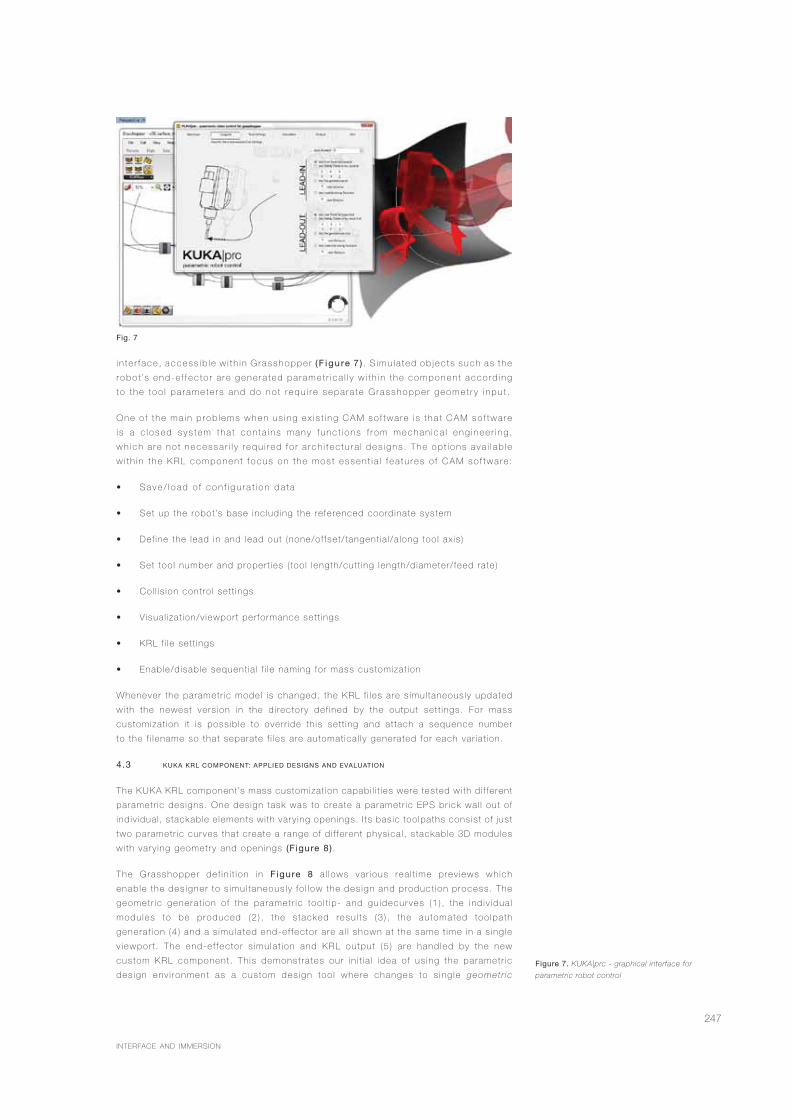
in te r f ace , access ib l e w i t h i n G rasshoppe r ( F igu re 7 ) . S imu l a t ed ob j ec t s such as t he
r obo t ’s end -e f f ec to r a r e gene ra ted pa rame t r i ca l l y w i t h i n t he componen t acco rd i ng
t o t he t oo l pa rame te r s and do no t r equ i r e sepa ra te G rasshoppe r geome t r y i npu t .
One o f t he ma in p rob l ems when us i ng ex i s t i ng CAM so f twa re i s t ha t CAM so f twa re
i s a c l osed sys tem tha t con ta i ns many f unc t i ons f r om mechan i ca l eng i nee r i ng ,
wh i ch a re no t necessa r i l y r equ i r ed f o r a r ch i t ec tu r a l des i gns . The op t i ons ava i l ab l e
w i t h i n t he KRL componen t f ocus on t he mos t essen t i a l f ea tu res o f CAM so f twa re :
S a v e / l o a d o f c o n f i g u r a t i o n d a t a
Set up the robot ’s base inc lud ing the re ferenced coord inate system
Def ine the lead in and lead out (none/of fset/ tangent ia l /a long too l ax is )
Set too l number and proper t ies ( too l length/cut t ing length/d iameter/ feed rate)
Col l is ion cont ro l set t ings
Visua l izat ion/v iewport per formance set t ings
KRL f i le set t ings
Enable/d isable sequent ia l f i le naming for mass customizat ion
Whenever the parametr ic model is changed, the KRL f i les are s imul taneous ly updated
wi th the newest vers ion in the d i rectory def ined by the output set t ings. For mass
customizat ion i t is poss ib le to over r ide th is set t ing and at tach a sequence number
to the f i lename so that separate f i les are automat ica l ly generated for each var ia t ion.
4.3 KUKA KRL COMPONENT: APPLIED DESIGNS AND EVALUATION
The KUKA KRL component ’s mass customizat ion capabi l i t ies were tested wi th d i f fe rent
parametr ic des igns. One des ign task was to create a parametr ic EPS br ick wal l out of
ind iv idua l , s tackable e lements wi th vary ing openings. I ts bas ic too lpaths cons is t o f just
two parametr ic curves that create a range of d i f fe rent phys ica l , s tackable 3D modules
wi th vary ing geometry and openings (F igure 8) .
The Grasshopper de f in i t ion in Figure 8 a l lows var ious rea l t ime prev iews wh ich
enab le the des igner to s imu l taneous ly fo l low the des ign and product ion process. The
geomet r ic genera t ion o f the paramet r ic too l t ip- and gu idecur ves (1 ) , the ind iv idua l
modu les to be produced (2 ) , the s tacked resu l ts (3 ) , the automated too lpa th
genera t ion (4 ) and a s imu la ted end-e f fec to r a re a l l shown a t the same t ime in a s ing le
v iewpor t . The end-e f fec to r s imu la t ion and KRL output (5 ) a re hand led by the new
custom KRL component . Th is demonst ra tes our in i t i a l idea o f us ing the paramet r ic
des ign env i ronment as a custom des ign too l where changes to s ing le geomet r ic
Fig. 7
Figure 7. KUKA|prc - graphical interface for
parametric robot control
INTERFACE AND IMMERSION

248
INTEGRATION THROUGH COMPUTATIONACADIA 2011 _PROCEEDINGS
Fig. 8
modu les , o r to the overa l l des ign, have immedia te consequences fo r the too lpa th
genera t ion and v ice versa.
In contrast to traditional CAM software, this modular approach allows an open and flexible
parametric CAM environment, where the user does not necessarily have to rely on pre-
set toolpath-strategies, but can substitute these components with his own parametric
Grasshopper definitions.
To compare the Grasshopper integrated KUKA plugin with traditional CAD/CAM, two prototypes
of the same parametric wall design were milled. The physical models of both results were
indistinguishable, while the preparation with the commercial CAM software took only slightly
longer compared to the KRL component. However, any successive variation would widen the
time-gap as the CAD/CAM software has to be set up each time, while the KRL component
can continue generating KRL code instantly. For the design variant in Figure 8, the toolpath
consists of 1500 points. The KRL file is generated within 45ms on a 2GHz laptop, which would
theoretically allow the automated output of 20 design variants per second. This rapid response
allows designers to quickly output and fabricate design variants, without having to manually
process each file in the CAM software and postprocess for the robot´s kinematics. A further
advantage is that the calculations happen parallel to the design process: while the designer can
“play” with the geometric entities such as curves and stackable 3D modules, the KUKA plugin
provides feedback on fabrication feasibility and possible collisions.
In order to evaluate the Grasshopper-integrated KUKA plugin with a full scale architectural
prototype, we revisited “Plug & Play,” a robotically fabricated project from 2009/2010 that
required the fabrication of 18 unique freeform panels for a 12m² freeform interior surface as part
of a children´s playground design (Figure 9). Different milling strategies such as roughening,
finishing and flank milling were evaluated and successfully used with the KUKA plugin.
Figure 8. Production immanent parametric model
simultaneously showing realtime preview of
geometry input (1), individual modules (2), final
design (3), milling simulation with feasibility analysis
(4) and KRL code (5)
Figure 9. 12m² freeform surface segmented in 18
panels (left), comparing flank milling and point milling
according to material efficiency (middle, right)
Fig. 9

249
Roughening and finishing are common point milling strategies that use the tooltip of the endmill
to coarsely remove stock material layer by layer (roughening), and then to create the final
surface finish (finishing). In contrast, flank milling (Schindler 2009) utilizes the whole cutting
length of the endmill to tangentially cut finished surfaces out of the stockmodel.
Due to these inherent d i f fe rences between point and f lank mi l l ing st ra teg ies, two
separate approaches were deve loped to produce the shape of the panels. For
roughening/ f in ish ing, severa l b locks of XPS were used to mi l l the f ina l sur face. For
f lank mi l l ing, the f reeform shape was approx imated wi th ru led sur faces wi th the width
of each sur face cor responding to the he ight of a common XPS panel . A s ing le cut was
then per formed to produce the f in ished sur faces.
Both from the computat ional and physical point of view, f lank mil l ing proved to be the
best solut ion for this part icular project. Compared to the point mi l l ing strategies, f lank
mil l ing required approximately 80% less toolpath length, which equals machine t ime, and
achieved more than 40% in material savings (Figure 9). Simi lar results for f lank mil l ing
appl icat ions were reported by Waldt (2005).
Figure 10 shows the comparison of the proposed milling strategies of an exemplary panel in
commercial CAM software and the impact of flank milling on toolpath lengths and machine time.
The increased toolpath length of point milling also has consequences for the parametric design
environment, as the robot code generation is noticeably slowed down by the excessive amount
of data. In the freeform playground design only flank milling allows the designer to work in
a fluent, near realtime design environment. The right choice of milling strategies is therefore
crucial for the parametric design environment and efficiency of mass customization. Therefore
the designer has to evaluate milling strategies before creating a parametric model. Any design-
to-fabrication automation requires milling experience to allow such decisions.
The two realized examples, the parametric wall and the children´s playground design presented
in this paper show that parametric design software with integrated CAD/CAM features is
capable of accommodating customized and optimized fabrication strategies that would not be
possible using traditional CAM software tools only. Significant savings in machining time and
material costs, along with the ecological aspect of producing less waste, can be achieved by
optimizing designs for fabrication instead of just sending the final 3D CAD file to the fabrication
workshop. The KUKA component for Grasshopper enables a fluid workflow from optimized
design to robotic fabrication.
INTERFACE AND IMMERSION
Fig. 10
Fig. 11
Figure 10. Freeform playground: comparing point-
and flank milling strategies
Figure 11. Modular, parametric robot control using
KUKA|prc

250
INTEGRATION THROUGH COMPUTATIONACADIA 2011 _PROCEEDINGS
5 Conclusion and Out look
Industrial robots have been applied in full-scale construction – as a replacement for manual labor – in
Japan since the 1980s with little success due to automation difficulties and economic reasons. As
Bechthold (2010) states, the development of automated programming strategies is fundamental for
using robots in “customized construction”.
Our intent in research is to enable a wide range of architects in the use of robots with a similar ease of
use compared to conventional CNC-machines and an intuitive approach towards mass customization.
The presented parametric interface in this paper is a first step for industrial robots to be used as full scale
construction technology by a broad range of designers and CAD users.
From the architectural design point of view we would like to “play” with robotically manufactured designs,
where all necessary constraints are integrated in a parametric model. Our approach of designing the
KUKA|prc component for milling, is - compared to Gramazio and Kohler´s robotically bricklaid walls - of
course a geometrically less complex problem to solve, but demonstrates a certain playfulness in design
and ease in the creation of an interface for the use of a technically sophisticated CNC machine such
as a KUKA robot. The multifunctionality of Grasshopper can be compared to the multifunctionality of
an industrial robot where the designer can plug and unplug different tools like milling-cutters for robot
milling or gripping tools for bricklaying (Figure 11). It allows the expectation that the presented KUKA|prc
component in this paper is modifiable to achieve a wide variety of robot applications by simple plugging
and unplugging different geometric solutions or tool constraints, enabling us to integrate industrial robots
in CAAD and move beyond CAD/CAM as we know it (Figures 12, 13).
Acknowledgements
The projects in Figure 12 (Parametric Punching by Michael Vasku) and Figure 13 (Lightpainting by Vera
Kumer) resulted from testing the KUKA|prc plugin in the lecture “Digital Design to Production” at Vienna
UT. We would like to thank all of our students for their enthusiasm, and the Association for Robots in
Architecture, Vienna University of Technology, the Innovative Project “Geometric Model Building with
CNC-Technologies”, the “7-Axis CNC Milling with an Industrial Robot in Architecture” project, and KUKA
CEE for their kind support of our research.
Fig. 12
Fig. 13
Figure 12. Robotic fabrication beyond CAD/CAM:
parametric punching – toolpath generation via
image sampling
Figure 13. Robotic fabrication beyond CAD/CAM:
lightpainting

251
References
Bärtsch i , R. , M. Knauss, T. Bonwetsch, F. Gramaz io, and M. Kohler. 2010. W iggled
Br ick Bond, Advances in Arch i tectura l Geometr y 2010: 137-148, V ienna: Spr inger.
Bechtho ld, M. 2010. The Return of the Future- A Second Go at Robot ic Const ruct ion
, Archi tectura l Des ign 80(4) :116-121. Hoboken: W i ley and Sons.
Biggs, G. and B. MacDonald. 2003. A Survey of Robot Programming Systems.
Proceedings of the Aust ra las ian Conference on Robot ics and Automat ion , CSIRO .
Br isbane.
Bre l l -Cokcan, S. and J. Braumann. 2010. A New Parametr ic Des ign Tool for Robot
Mi l l ing. Proceedings of the 30th Annual Conference of the Associat ion for Computer
A ided Des ign in Arch i tecture : 357-363. New York.
Bre l l -Cokcan, S. , M. Reis, H. Schmiedhofer, and J. Braumann. 2009. Dig i ta l Des ign
to Dig i ta l Product ion: F lank Mi l l ing wi th a 7-Ax is Robot and Parametr ic Des ign.
Computat ion: The New Realm of Arch i tectura l Des ign. 27th eCAADe Conference
Proceedings : 323-330. Is tanbul .
Eastman, C., P. Te icholz , R. Sacks, and K. L is ton. 2008. B IM Handbook . Hoboken,
New Jersey: W i ley and Sons.
E igensatz, M., M. K i l ian, A. Schi f tner, N. Mi t ra, H. Pot tmann, and M. Pauly. 2010.
Panel ing Arch i tectura l Freeform Sur face. ACM Transact ions on Graphics 29(4) . New
York: ACM.
Gramaz io, F. and M. Kohler. 2008. D ig i ta l Mater ia l i t y in Arch i tecture . Baden: Lars
Mül ler Publ ishers.
Iwamoto, L. 2009. Dig i ta l Fabr icat ion: Archi tectura l and Mater ia l Techniques . New
York: Pr inceton Arch i tectura l Press.
Kolarev ic, B. and K. K l inger. 2008. Manufactur ing Mater ia l E f fects – Reth ink ing Des ign
and Making in Arch i tecture . New York: Rout ledge.
KUKA Robot ics. 2003. KR C2 / KR C3 Exper t Programming . Augsburg: KUKA Roboter
GmbH.
Mühe, H., A. Angerer, A. Hof fmann, and W. Rei f . 2010. On reverse-engineer ing
the KUKA Robot Language. Proceedings of the DSLRob’10, IEEE/RSJ In ternat iona l
Conference on In te l l igent Robots and Systems 2010 , Ta ipeh.
P i l le r, F. 2004. Mass Customizat ion: Ref lect ions on the State of the Concept. The
In ternat iona l Journa l o f F lex ib le Manufactur ing Systems 16:313-334. Spr inger.
Ramani , K. , R. Cunningham, S. Devanthan, J. Subramaniam, and H. Patwardhan. 2004.
Technology Rev iew of Mass Customizat ion . Product Models Organizat ion Conference
2004.
Scheurer, F. 2010. Mater ia l is ing Complex i ty. Archi tectura l Des ign 80(4) . Hoboken:
W i ley and Sons.
Schind ler, C. 2009. F lankenf räsen. In Ein arch i tekton isches Parametr is ierungsmodel l
anhand Fer t igungstechnischer Kr i ter ien, dargeste l l t am Holzbau , Zür ich: ETH Zür ich.
Takase, K. , R. Paul , and E. Berg. 1981. A St ructured Approach to Robot Programming
and Teaching, IEEE Transact ions on Systems, Man, and Cybernet ics 1 (4) . New York:
IEEE.
Waldt , N. 2005. NC-Programmierung für das fünfachs ige F lankenf räsen von
Fre i formf lächen . Hannover: Univers i tä t Hannover.
INTERFACE AND IMMERSION