Parallel Optical All Pass Filter Equalisers and Implementation by Wisit Loedhammacakra Supervision...
27
Parallel Optical All Pass Filter Equalisers and Implementation by Wisit Loedhammacakra Supervision team Dr Wai Pang Ng Prof R. Cryan Prof. Z. Ghassemlooy Northumbria Communication Research Laboratories (NCRL) Northumbria University
-
date post
21-Dec-2015 -
Category
Documents
-
view
218 -
download
3
Transcript of Parallel Optical All Pass Filter Equalisers and Implementation by Wisit Loedhammacakra Supervision...

Parallel Optical All Pass Filter Equalisers and Implementation
by
Wisit Loedhammacakra
Supervision team
Dr Wai Pang NgProf R. Cryan
Prof. Z. Ghassemlooy
Northumbria Communication Research Laboratories (NCRL)Northumbria University
13th June 2007

Overview
• Long-haul communication systems• Problem Statement• Chromatic Dispersion• Parallel Optical All Pass Filter Equaliser• Conclusion

Ideal communication system:
• Unlimited transmission bit rate (B)
• Unlimited transmission distance (L)
Long-haul Communication System 1Ideal Communication Systems
Tx Rx
• Audio
• Video
• Data
AttenuationAttenuation and dispersiondispersion limit BL product (as a benchmark for system’s performance)
Quality of digital communication systems can be
monitored from bit error rate (BER) of system.
Error-free detection, BER less than 10e-9
(Single error in one billion transmitted bits)
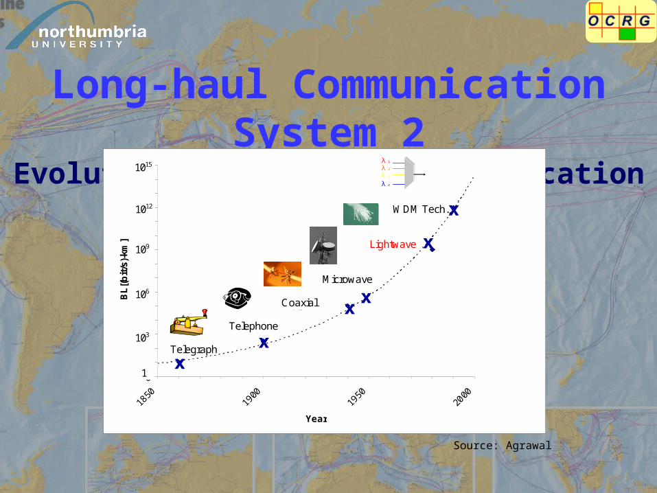
Long-haul Communication System 2Evolution of Long-haul communication systems
0
1
2
3
4
5
6
7
8
9
10
11
12
13
14
15
1850
1900
1950
2000
Year
BL
[(b
it/s
)-km
]
1015
103
106
109
1012
Lightwave
1
Telegraph
Coaxial cables
Telephone
Microwave
WDM Tech.
λ 1
λ 2
λ 3
λ n
Source: Agrawal
xx
x
x
x
x

Long-haul Communication System 3Optical Communication systems
1st 1970s 0.8 μm 1 dB/km 45 M 10 km MMFElectronic repeater
2nd 1980s 1.3 μm 0.5 dB/km 100 M 50 km MMFElectronic repeater
3rd 1990 1.55 μm 0.2 dB/km 2.5 G 70 km SMFElectronic repeater
4th 1996 1.55 μm 0.2 dB/km 2.5 G 100 km SMFEDFA WDM
5th 1999 1.55 μm 0.2 dB/km 10 G 100 km SMFCD
compen-sation
Generation YearOperation
wavelengthAttenuation
Bit rate bit/s
Repeat length
Fibre type
Special system

Problem StatementSingle Mode Fibre (SMF)
Wavelength (µm)
Fib
re a
tten
uati
on (
dB/k
m)
1.2 1.3 1.4 1.5 1.635
3025201510505
101520253035
Material dispersionWaveguide dispersionChromatic dispersion
Wavelength
Dis
pers
ion
(ps/
nm-k
m)
Dis
pers
ion
(ps/
nm-k
m)
Wavelength (µm)
• 1.31 μm chromatic dispersion (CD) is zero, but high attenuation is 0.5 dB/km.
• 1.55 μm has high CD of 17 ps/nm-km while attenuation is the lowest (0.2 dB/km).
Attenuation Dispersion ??

Chromatic Dispersion 1
Magic refresh room
Dispersion compensator
0 1 0 0 1 0 0 1 0
OAPF
1 0 1 Pattern 100 Pattern 001 Pattern 101 0? or 1?
1 0 1
Fibre
Transmitted pulse
restored pulse
Dispersed pulse
3 bits pattern of restored pulse3 bits pattern of dispersed pulse

Chromatic Dispersion 2
Why I’m so slow???
I’m not better, but my path has less resistance!!!
λ3
λ2
λ1
Core of fibre

Chromatic Dispersion 3Output Pulses of Different Lengths of SMF
200 150 100 50 0 50 100 150 200 250 3000
0.25
0.5
0.75
1
Original pulseSMF 80 kmSMF 100 kmSMF 160 km
Time (ps)
Am
pli
tude
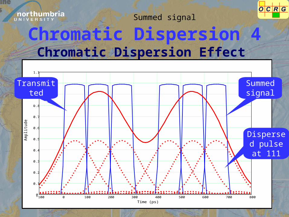
Chromatic Dispersion 4Chromatic Dispersion Effect
100 0 100 200 300 400 500 600 700 8000
0.1
0.2
0.3
0.4
0.5
0.6
0.7
0.8
0.9
1
1.1
Time (ps)
Am
pli
tude
Summed signal
Summed signal
Dispersed pulse at 111
km
Transmitted pulse

Chromatic Dispersion 5 The Bit Rate-length Product
• Doubling the bit rate (B) would reduce the repeater-less length (L) of optical communication systems by a factor of 4.
• CD is the main limiting factor for repeater-less length.
220
c
4 λB L
D
L = 312 kmL = 18 kmL = 437 km10 Gb/s
L = 4,995 kmL = 294 kmL = 6,993 km2.5 Gb/s
DSF 1.55 μm
D ~ 1 ps/nm-km
SMF 1.55 μm
D ~ 17 ps/nm-km
SMF 1.3 μm
D ~ 1 ps/nm-km
Bit rate
Repeater-less length of optical communication systems
L = 312 kmL = 18 kmL = 437 km10 Gb/s
L = 4,995 kmL = 294 kmL = 6,993 km2.5 Gb/s
DSF 1.55 μm
D ~ 1 ps/nm-km
SMF 1.55 μm
D ~ 17 ps/nm-km
SMF 1.3 μm
D ~ 1 ps/nm-km
Bit rate
Repeater-less length of optical communication systems
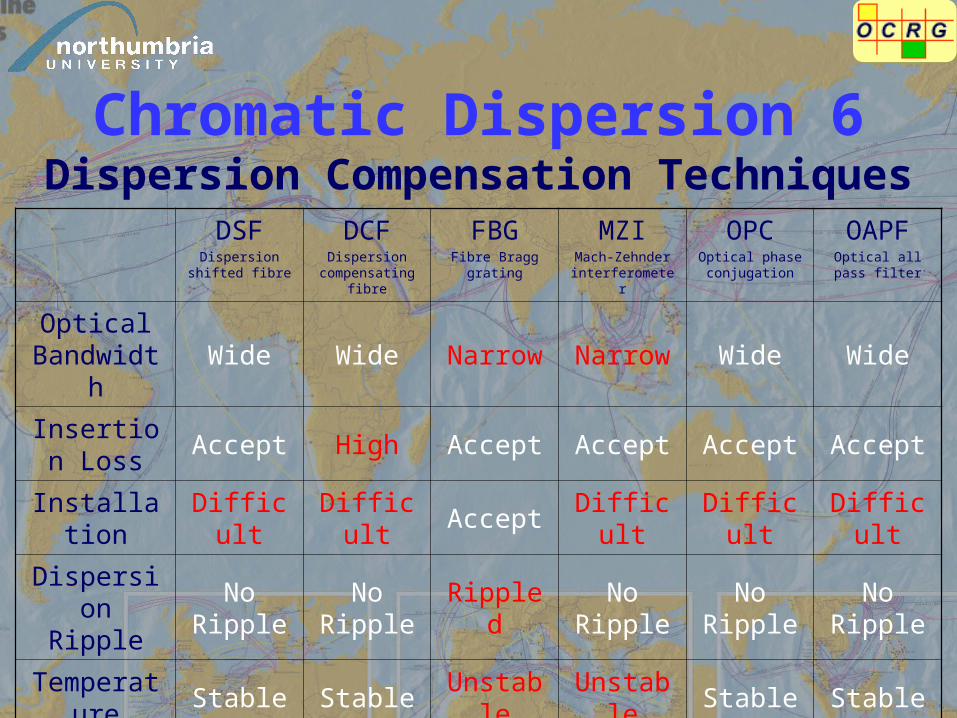
Chromatic Dispersion 6Dispersion Compensation Techniques
DSFDispersion shifted
fibre
DCFDispersion
compensating fibre
FBGFibre Bragg grating
MZIMach-Zehnder interferometer
OPCOptical phase conjugation
OAPFOptical all pass
filter
Optical Bandwidth
Wide Wide Narrow Narrow Wide Wide
Insertion Loss
Accept High Accept Accept Accept Accept
Installation Difficult Difficult Accept Difficult Difficult Difficult
Dispersion Ripple
No Ripple
No Ripple
RippledNo
RippleNo
RippleNo
Ripple
Temperature Stable Stable Unstable Unstable Stable Stable
Dispersion Tunable
No No Possible Possible No Possible
Cost High High Accept High High Accept

Parallel optical all pass filter equaliserParallel optical all pass filter equaliser
(p-OAPF)(p-OAPF)
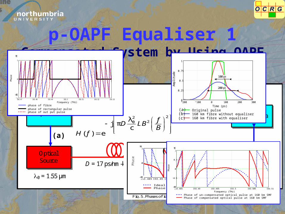
p-OAPF Equaliser 1Compensated System by Using OAPF
B = 10 Gb/s
OOK NRZ Format
0 = 1.55 μm
Input Data Output Data
Photo Detector
OAPF Equaliser
Optical Source D = 17 ps/nm-km, L = 160 km
2220λ
j πc
( ) e
fD LB
BH f
[ jφ(ω)](ω) eOAPFH
193.47 193.48 193.49 193.5 193.51 193.52 193.531
0
1
phase of fibrephase of rectangular pulsephase of out put pulse
Frequency (THz)
Pha
se
π
-π
193.485193.49 193.495 193.5 193.505 193.51 193.5151
0
1
Ideal phase of equaliser for 160 km SMFPhase of OAPF equaliser
Frequency (THz)
Phase
π
-π
Fig. 5. Phases of ideal equaliser for 160 km and OAPF.
200 100 0 100 200 3000
0.25
0.5
0.75
1
Original pulse160 km fibre without equaliser160 km fibre with equaliser
Time (ps)
Am
plit
ude
100 ps
200 ps
(a)(b)(c)
(a)
(b) (c)
193.485 193.49 193.495 193.5 193.505 193.511
0.5
0
0.5
1
Phase of un-compensated optical pulse at 160 km SMFPhase of compensated optical pulse at 160 km SMF
Frequency (THz)
Pha
se
π
-π
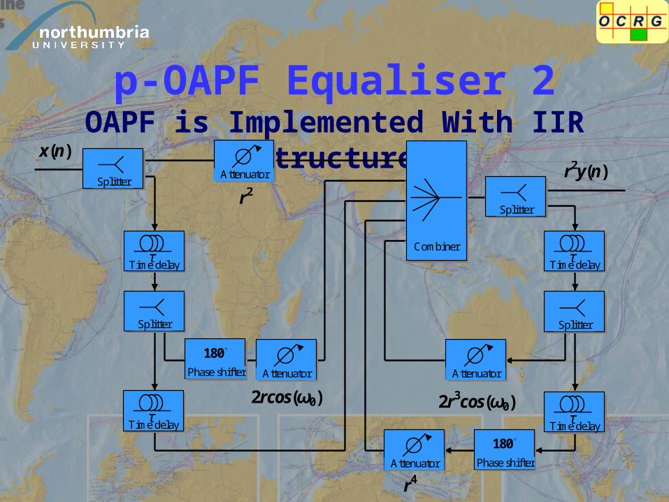
p-OAPF Equaliser 2OAPF is Implemented With IIR Structure
x(n)
r2y(n)
r4
r2
2rcos(ω0)
2r3cos(ω0)
Splitter
Splitter
Splitter
Splitter
Attenuator
Attenuator
Attenuator
Attenuator
180◦
Phase shifter
180◦
Phase shifter
Time delay τ
Time delay τ
Time delay τ
Time delay τ
Combiner

p-OAPF Equaliser 3Compensated System by Using p-OAPF
B = 10 Gb/s
OOK NRZ Format
0 = 1.55 μm, Pi = 1 mW
Input Data Output Data
Optical Source
D = 17 ps/nm-km, α = 0.2 dB/km, L = 90 km
EDFA OBPF p-OAPF Equaliser
G = 30 dB BW = 20 GHz
Eq1
Eq2 Photo Detector
Photo Detector
Splitter
Electrical signal
Optical signal
0
α
10
22λ 2j πc
( ) 10 eL
f
fD LB
BH f
193.40935 193.41435 193.41935 193.42435 193.429351
0
1
Phase response of rectangular pulse.Phase response of SMF at 90 km.Compensated phase response by p-OAPF.
Frequency (GHz)
Phas
e (p
i)
-π
π
Phas
e
150 200 250 300 350 400 450 500 5500
0.2
0.4
0.6
0.8
1
1.2
Original pulseDispersive pulse at 90 km of SMFCompensated pulse by p-OAPF
Time (ps)
Nor
mal
ised
Am
plit
ude
350 300 400 250
Time (ps) N
orm
alis
ed A
mpl
itude
0
0.2
0.4
0.6
0.8
1
1.2
2.50E-10 3.00E-10 3.50E-10 4.00E-10 4.50E-10
450

Conclusion
p-OAPFp-OAPF
Be implemented in optical domain by
using IIR structure and optical components
Adjust the phase of the optical pulse
back to the phase of transmitted optical
pulse
Capable of extending the
length to 90 km in 10 Gb/s systems
CD limits 10 Gb/s system at
30 km

Publications1. W. Loedhammacakra, W. P. Ng, and R. A. Cryan, "Investigation of an Optical All Pass Filter for a 10 Gb/s Optical Communication System," presented at PG-NET 2005 Proceeding, Liverpool John Moores University, UK, pp. 170-175, 27-28 June 2005.
2. W. Loedhammacakra, W. P. Ng, and R. A. Cryan, "An Improved Chromatic Dispersion Compensation Technique Employing an Optical All Pass Filter Equaliser in a 10Gb/s Optical System," presented at The Tenth High Frequency Postgraduate Student Colloquium, University of Leeds, UK, pp. 105-108, 5-6 September 2005.
3. W. Loedhammacakra, W. P. Ng, and R. A. Cryan, "Chromatic Dispersion Compensation Using an Optical All Pass Filter for a 10 Gb/s Optical Communication System at 160 km," presented at London Communication Symposium 2005, University College London, UK, pp. 255-258, 8-9 September 2005.
4. W. Loedhammacakra, W. P. Ng, and R. A. Cryan, “Chromatic Dispersion Compensation Employing Optical All Pass Filter by Using IIR Structure for 10 Gb/s Optical Communication System,” presented at the IEE Photonics Professional Network Seminar on Optical Fibre Communications and Electronic Signal Processing, The IEE Savoy place, London, UK, pp 17/1-17/6, 15 December 2005.
5. W. Loedhammacakra, W. P. Ng, R. A. Cryan, and Z. Ghassemlooy, “Investigation of Optical All Pass Filter to Compensate Chromatic Dispersion in a 10 Gb/s Optical Communication System at 160 km,” CSNDSP 2006, Patras, Greece, pp. 454 – 458, 19 – 21 July 2006.
6. W. P. Ng, W. Loedhammacakra, R. A. Cryan, and Z. Ghassemlooy, “Performance Analysis of the Parallel Optical All-pass Filter Equalizer for Chromatic Dispersion Compensation at 10 Gb/s,” under-review by Globecom 2007.
7. W. P. Ng, W. Loedhammacakra, R. A. Cryan, and Z. Ghassemlooy, “Characterisation of a Parallel Optical All Pass Filter for Chromatic Dispersion Equalisation in 10 Gb/s System ,” under-review by IET processing on signal processing.
Posters1. Chromatic Dispersion Compensation Technique Employing OAPF in Optical Communication Systems, presented at UK Grad Poster Competitive 2006, Northumbria University, Newcastle, Aril 2006.
2. High Speed Optical Network Need Low Dispersion, presented at Britain’s Early-State Engineers on UK Engineering research and R&D, House of Commons, London, December 2006.
Papers

Acknowledgements
My supervision team (Dr. Wai Pang Ng, Prof. R. Cryan and Prof. Z. Ghassemlooy)
OCR Group leader (Prof. Z. Ghassemlooy) for all of his support
Dr Krishna Busawon and Dr Mark Leach for all of the useful discussions we had
My colleague in Room E405 and E409 Especially, Hoa, Popoola, Sujan and Ming Feng for discussion and helpful.
I would like to thank:

Thank you
Discussion
Question&

Optical All Pass Filter Equaliser 1 Phases of SMF, Rectangular and Dispersed Pulse
193.47 193.48 193.49 193.5 193.51 193.52 193.531
0
1
phase of fibrephase of rectangular pulsephase of out put pulse
Frequency (THz)
Pha
se
π
-π
• The interested bandwidth is between 193.49 – 193.51 THz, which phase response of dispersed pulse is same as phase response of SMF.

Optical All Pass Filter Equaliser 2Phase Response of Ideal Equaliser and OAPF
193.485193.49 193.495 193.5 193.505 193.51 193.5151
0
1
Ideal phase of equaliser for 160 km SMFPhase of OAPF equaliser
Frequency (THz)
Phase
π
-π
Fig. 5. Phases of ideal equaliser for 160 km and OAPF.
• The phase response of the ideal equaliser is used as the optimisation criterion.
• The phase response of OAPF at upper frequency does not equalise properly.

Optical All Pass Filter Equaliser 3Optical Communication System
B = 10 Gb/s
OOK NRZ Format
0 = 1.55 μm
Input Data Output Data
Photo Detector
OAPF Equaliser
Optical Source D = 17 ps/nm-km, L = 160 km
2220λ
j πc
( ) e
fD LB
BH f
[ jφ(ω)](ω) eOAPFH
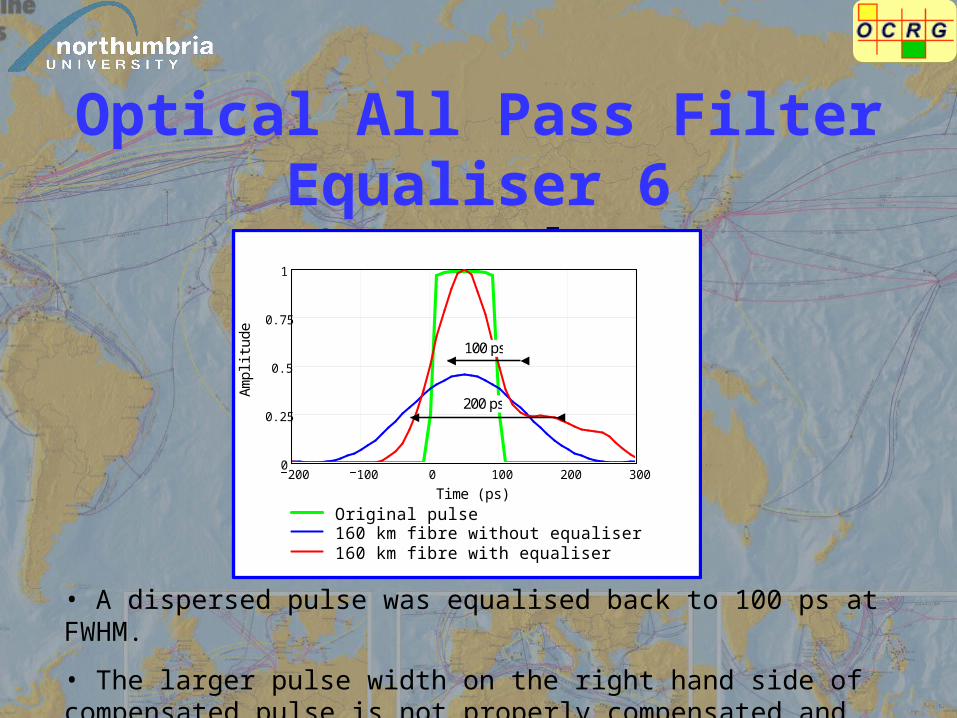
Optical All Pass Filter Equaliser 6Output Pulses
200 100 0 100 200 3000
0.25
0.5
0.75
1
Original pulse160 km fibre without equaliser160 km fibre with equaliser
Time (ps)
Am
plit
ude
100 ps
200 ps
• A dispersed pulse was equalised back to 100 ps at FWHM.
• The larger pulse width on the right hand side of compensated pulse is not properly compensated and resulted in higher ISI and BER.
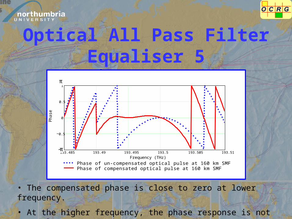
Optical All Pass Filter Equaliser 5Phase response
193.485 193.49 193.495 193.5 193.505 193.511
0.5
0
0.5
1
Phase of un-compensated optical pulse at 160 km SMFPhase of compensated optical pulse at 160 km SMF
Frequency (THz)
Pha
se
π
-π
• The compensated phase is close to zero at lower frequency.
• At the higher frequency, the phase response is not properly compensated.

Results 1Compensated Phase Response by p-OAPF
193.40935 193.41435 193.41935 193.42435 193.429351
0
1
Phase response of rectangular pulse.Phase response of SMF at 90 km.Compensated phase response by p-OAPF.
Frequency (GHz)
Phas
e (p
i)
-π
π Ph
ase

Results 2Compensated Pulse by p-OAPF
150 200 250 300 350 400 450 500 5500
0.2
0.4
0.6
0.8
1
1.2
Original pulseDispersive pulse at 90 km of SMFCompensated pulse by p-OAPF
Time (ps)
Nor
mal
ised
Am
plit
ude
350 300 400 250
Time (ps)
Nor
mal
ised
Am
plitu
de
0
0.2
0.4
0.6
0.8
1
1.2
2.50E-10 3.00E-10 3.50E-10 4.00E-10 4.50E-10
450