Parallel matrix transpose algorithms on distributed memory ...
19
ELSEVIER Parallel Computing 21(1995) 1387-1405 PARALLEL COMPUTING Parallel matrix transpose algorithms on distributed memory concurrent computers ’ Jaeyoung.Choi a,*, Jack J. Dongarra b,c, David W. Walker b ’ School of Compuring, Soongsil Uniuersiiy, l-l Sangdo-Dong, Dongjak-Ku, Seoul 156-743, South Korea ’ Mathematical Sciences Section, Oak Ridge National Laboratory, P.O. Box 2008, Bldg. 6012, Oak Ridge, TN 378314367, USA ’ Department of Computer Science, University of Tennessee al Knoxville, 107Ayres Hall, Knoxville, TN 379961301, USA Received 12 November 1993, revised 25 August 1994,4 January 1995; accepted 20 February 1995 Abstract This paper describes parallel matrix transpose algorithms on distributed memory concur- rent processors. We assume that the matrix is distributed over a P x Q processor template with a block cyclic data distribution. P, Q, and the block size can be arbitrary, so the algorithms have wide applicability. The communication schemes of the algorithms are determined by the greatest common divisor (GCD) of P and Q. If P and Q are relatively prime, the matrix transpose algorithm involves complete exchange communication. If P and Q are not relatively prime, processors are divided into GCD groups and the communication operations are overlapped for different groups of processors. Processors transpose GCD wrapped diagonal blocks simulta- neously, and the matrix can be transposed with LCM/GCD steps, where LCM is the least common multiple of P and Q. The algorithms make use of non-blocking, point-to-point communication between proces- sors. The use of nonblocking communication allows a processor to overlap the messages that it sends to different processors, thereby avoiding unnecessary synchronization. Combined with the matrix multiplication routine, C = A. B, the algorithms are used to compute parallel multiplications of transposed matrices, C = AT. BT, in the PUMMA package [s]. Details of the parallel implementation of the algorithms are given, and results are presented for runs on the Intel Touchstone Delta computer. * Research was supported by the Applied Mathematical Sciences Research Program of the Office of Energy Research, U.S. Department of Energy, by the Defense Advanced Research Projects Agency under contract DAAL03-91-C-0047, administered by the Army Research Office, and by the Center for Research on Parallel Computing. * Communicating author. Email: [email protected]. 0167~8191/95/$09.50 0 1995 Elsevier Science B.V. All rights reserved SSDI 0167-8191(95)00016-X
Transcript of Parallel matrix transpose algorithms on distributed memory ...
ELSEVIER Parallel Computing 21(1995) 1387-1405
PARALLEL COMPUTING
Parallel matrix transpose algorithms on distributed memory concurrent computers ’
Jaeyoung.Choi a,*, Jack J. Dongarra b,c, David W. Walker b
’ School of Compuring, Soongsil Uniuersiiy, l-l Sangdo-Dong, Dongjak-Ku, Seoul 156-743, South Korea ’ Mathematical Sciences Section, Oak Ridge National Laboratory, P.O. Box 2008, Bldg. 6012, Oak Ridge,
TN 378314367, USA
’ Department of Computer Science, University of Tennessee al Knoxville, 107Ayres Hall, Knoxville, TN 379961301, USA
Received 12 November 1993, revised 25 August 1994,4 January 1995; accepted 20 February 1995
Abstract
This paper describes parallel matrix transpose algorithms on distributed memory concur-
rent processors. We assume that the matrix is distributed over a P x Q processor template with a block cyclic data distribution. P, Q, and the block size can be arbitrary, so the algorithms have wide applicability. The communication schemes of the algorithms are determined by the greatest common divisor (GCD) of P and Q. If P and Q are relatively prime, the matrix transpose algorithm involves complete exchange communication. If P and Q are not relatively prime, processors are divided into GCD groups and the communication operations are overlapped for different groups of processors. Processors transpose GCD wrapped diagonal blocks simulta- neously, and the matrix can be transposed with LCM/GCD steps, where LCM is the least common multiple of P and Q. The algorithms make use of non-blocking, point-to-point communication between proces- sors. The use of nonblocking communication allows a processor to overlap the messages that it sends to different processors, thereby avoiding unnecessary synchronization. Combined with the matrix multiplication routine, C = A. B, the algorithms are used to compute parallel multiplications of transposed matrices, C = AT. BT, in the PUMMA package [s]. Details of the parallel implementation of the algorithms are given, and results are presented for runs on the Intel Touchstone Delta computer.
* Research was supported by the Applied Mathematical Sciences Research Program of the Office of Energy Research, U.S. Department of Energy, by the Defense Advanced Research Projects Agency under contract DAAL03-91-C-0047, administered by the Army Research Office, and by the Center for Research on Parallel Computing.
* Communicating author. Email: [email protected].
0167~8191/95/$09.50 0 1995 Elsevier Science B.V. All rights reserved SSDI 0167-8191(95)00016-X
1388 J. Choi et al. /Parallel Computing 21 (1995) 1387-1405
Keywords: Linear algebra; Matrix transpose algorithm; Distributed memory multiprocessors; Point-to-point communication; Intel Touchstone Delta
1. Introduction
Matrix transposition is a fundamental matrix operation of linear algebra [8,13] and arises in many scientific and engineering applications. On a uniprocessor, an algorithm involving a transposed matrix may not actually require the matrix data to be transposed in physical memory. Instead, it may be accessed simply by exchang- ing the row and column indices. However, in a distributed-memory multiprocessor environment, we cannot simply interchange the global row and column indices. Instead, the data must be physically moved from one processor to another.
Transposition of a matrix is a redistribution of its elements. Many researchers have considered the problem for different architectures. In 1972, Eklundh [7] considered the problem of directly accessing rows or columns of a matrix when its size is larger than the available high-speed storage. O’Leary [12] implemented an algorithm for transposing an N X N matrix on a one-dimensional systolic array. Azari, Bojanczyk and Lee [ll developed an algorithm for transposing an MxN
matrix on an N X N mesh-connected array processor, and Johnsson and Ho [lo] presented an algorithm for a Boolean n-cube, or hypercube.
Current advanced architecture computers possess hierarchical memories in which accesses to data in the upper levels of the memory hierarchy (registers, cache, and/or local memory) are faster than those in lower levels (shared or off-processor memory). To exploit the power of such machines, block-partitioned algorithms are preferred for dense linear algebra computations, in which opera- tions are performed on submatrices, rather than individual matrix elements. In distributing matrix data over processors we therefore assume a block cyclic data distribution [4,6]. The block cyclic data distribution can reproduce the most common data distributions used in dense linear algebra, as described briefly in Section 2.
In this paper, the parallel matrix transpose algorithms are presented based on the block cyclic data distribution. The algorithms are implemented on the Intel Touchstone Delta computer. The communication schemes of the algorithms are determined by the greatest common divisor (GCD) of the number of rows and columns (P and Q) of the processor template. If P and Q are relatively prime, the matrix transpose algorithm involves complete exchange communication. This is called all-to-all personalized communication, in which each of NP = P. Q proces- sors is required to send distinct subblocks to each of the remaining N, - 1 processors, and receive distinct subblocks from each of them. Bokhari and Berry- man [2] and Takkella and Seidel [14] have developed binary exchange and quadrant exchange algorithms on a circuit switched mesh, where P and Q are powers of 2. The complete exchange communication in our transpose algorithms arises for any processor configuration, and is not limited to the case where P and Q are powers of 2. We implemented the two-dimensional complete exchange
.I. Choi et al. /Parallel Computing 21 (1995) 1387-1405 1389
communication problem based on direct point-to-point communication scheme. If P and Q are not relatively prime, processors are divided into GCD groups and the communication operations are overlapped for different groups of processors. Processors transpose GCD wrapped diagonal blocks simultaneously, and the matrix can be transposed with LCM/GCD steps, where LCM is the least common multiple of P and Q. Details of the algorithms are discussed in Section 3.3.
We have presented the Parallel Universal Matrix Multiplication Algorithms (PUMMA) in [5’] for performing C * LY op(A) . op(B) + PC, where op(X) = X or XT, based on the block cyclic data distribution. One of the cases in the PUMMA package, C (= (Y AT. BT + PC is implemented in two steps (T e aB . A, C = T T + PC). The second step involves parallel matrix transposition. The performance of this algorithm for .evaluating C = AT * BT is compared with the algorithm for evaluating C = A * B on the Intel Delta machine in Section 4.
2. Design issues
The way in which an algorithm’s data is distributed over the processors of a concurrent computer has a major impact on the load balance and communication characteristics of the concurrent algorithm, and hence largely determines its performance and scalability. The block cyclic data distribution provides a simple, yet general-purpose way of distributing a block-partitioned matrix on distributed memory concurrent computers. In the block cyclic data distribution, described in detail in [4,6], an M X N matrix is partitioned into blocks of size r x c, and blocks separated by a fixed stride in the column and row directions are assigned to the same processor. If the stride in the column and row directions is P and Q blocks respectively, then we require that P * Q equal the number of processors, Np. Thus, it is useful to imagine the processors arranged as a P x Q mesh, or template. The processor at position (I?, 4) (0 sp < P, 0 I q < Q> in the template is assigned the blocks indexed by,
(p+i*P, q+.i.Q), (1) where i = 0 , . . . ,l(Mb -p - 1)/P], j = 0,. . . ,[(Nb -q - 11/Q], and Mb x Nb is the size in blocks of the matrix (Mb = [M/r], Nb = [N/c]).
Blocks are scattered in this way so that good load balance can be maintained in parallel algorithms, such as LU factorization [3,6]. The noncyclic distribution (or pure block distribution) is just a special case of the block cyclic distribution in which the block size is given by r = [M/PI and c = ]N/Ql. A purely cyclic distribution (or two-dimensional wrapped distribution) is another special case in which the block size is given by r = c = 1.
If P and Q are relatively prime, the matrix transpose algorithm involves a two-dimensional complete exchange communication, where each of N, processors is required to send distinct subblocks to each of the remaining N, - 1 processors, and receive distinct subblocks from each of them. We investigated to find the most efficient communication scheme for one-dimensional complete exchange commu- nication, which can be applied to the complicated two-dimensional complete

1390 J. Choi et al. /Parallel Computing 21 (1995) 1387-1405
~s~~~ / (~~(~~(5~ ; (,~~~~~~ 0
step 2 step3 . . . . . step 1 step 2 step 3 . . . . .
(a) Binary Exchange (b) Rotating (c) Direct Communication
Fig. 1. Three complete exchange communication schemes on 8 processors. The number in parentheses denotes the amount of data to transmit.
exchange communication. Three one-dimensional complete exchange communica- tion schemes are shown in Fig. 1, where each processor needs one subblock from each other processor, and the number in parentheses denotes the number of subblocks to transmit.
The binary exchange scheme completes in [log, PI steps and the amount of data transmitted in each step is fixed at 2r’0gz ‘l-l subblocks, where P is the number of processors. The rotating scheme can avoid network congestion, but requires P - 1 steps and the amount of data transmitted in the initial steps is large. In the direct point-to-point communication scheme, the number of steps is the same in the rotating scheme, but the amount of data transmitted in each step is only one subblock.
The three schemes have been implemented on 16 nodes of the Delta and their performances are compared in Fig. 2. The binary exchange and the rotating schemes are implemented with an odd-even communication scheme, which is preferable to a simultaneous communication scheme on the Delta [5,11]. In this algorithm, odd-numbered processors send their own blocks and even-numbered processors receive them in the first step, and even-numbered processors send and odd-numbered processors receive in the next step. On P = 2d processors, as shown in Fig. 2, the binary exchange scheme is the fastest. However, if P is not a power of 2, then this scheme becomes very complicated and may be slower than the direct communication scheme. The direct communication scheme is about 20% slower than the binary exchange scheme for the worst case (P = 2d>, but it is simple to implement on an arbitrary number of processors. We adopted the simple direct communication scheme for the implementation of the matrix transpose algorithms, which are explained in detail in the next section.
3. Matrix transpose algorithms
We assume that a matrix is distributed over a two-dimensional processor mesh, or template, so that in general each processor has several blocks of the matrix as

J. Choi et al. /Parallel Computing 21 (1995) 1387-1405 1391
Fig. 2.
1.0
0.5
I I I I I
.+ /’
,*’ ,’
.*’
,*’ I’ Rotating
,’ ,f’
/’ .*’
0.0 0 20 40 60 80 100
Block Size (Kbytes)
Comparison of three exchange communication schemes on 16 processors,
shown in Fig. 3(a), where a matrix with 12 X 12 blocks is distributed over a 2 x 3 template. Denoting the least common multiple of P and Q by LCM, we refer to a square of LCM x LCM blocks as an LCM block. Thus, the matrix may be viewed as a 2 x 2 array of LCM blocks, as shown in Fig. 3(b). The concept of the LCM block was introduced in Es], and is very useful for implementing algorithms that use a block cyclic data distribution. Blocks belong to the same processor if their relative locations are the same in each square LCh4 block. An algorithm may be
0 12 3 4 5 6 7 6 QlOfl 0 7 2 3 4 5 6 7 6 Q 1017
0 0 1 I 2 2 3 3 4 4 5 5 6 6 7 7 8 8 Q Q
10 IO 11 17
(a) block distribution over template (b) LCM bloci distribution
Fig. 3. A matrix with 12 X 12 blocks is distributed over a 2 x 3 processor template. (a) Each shaded and unshaded area represents different templates. The numbered squares represent blocks of elements, and the number indicates at which location in the processor template the block is stored - all blocks labeled with the same number are stored in the same processor. The slanted numbers, on the left and on the top of the matrix, represent indices of row block and column block, respectively. (b) The matrix has 2 x 2 LCM blocks. Blocks belong to the same processor if the relative locations of blocks are the same in each square LCM block. The definition of the LCM block is defined in the text.
1392 J. Choi et al. /Parallel Computing 21 (1995) 1387-1405
012345
0
1
2
3
4
5
072345
(a) matfix transpose from matrix point-of-view
A
031425
(b) matrix transpose from processor point-of-view
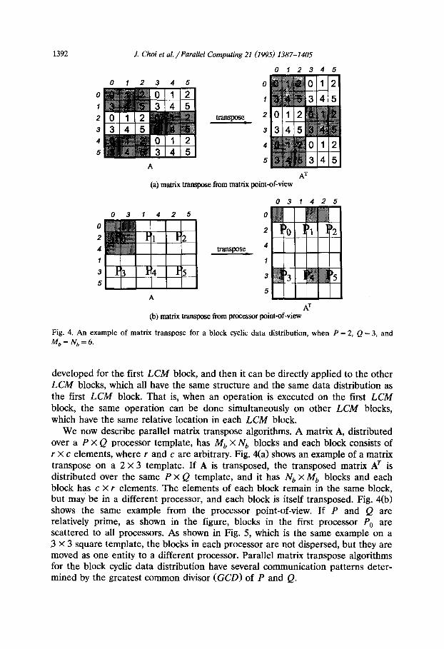
Fig. 4. An example of matrix transpose for a block cyclic data distribution, when P = 2, Q = 3, and M,, = Nb = 6.
developed for the first LCit4 block, and then it can be directly applied to the other LCM blocks, which all have the same structure and the same data distribution as the first LCM block. That is, when an operation is executed on the first LCM block, the same operation can be done simultaneously on other LCM blocks, which have the same relative location in each LCM block.
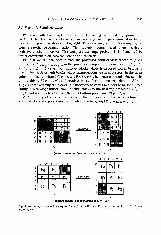
We now describe parallel matrix transpose algorithms. A matrix A, distributed over a P X Q processor template, has Mb X Nb blocks and each block consists of r x c elements, where I and c are arbitrary. Fig. 4(a) shows an example of a matrix transpose on a 2 x 3 template. If A is transposed, the transposed matrix AT is distributed over the same P x Q template, and it has Nb x Mb blocks and each block has c X r elements. The elements of each block remain in the same block, but may be in a different processor, and each block is itself transposed. Fig. 4(b) shows the same example from the processor point-of-view. If P and Q are relatively prime, as shown in the figure, blocks in the first processor PO are scattered to all processors. As shown in Fig. 5, which is the same example on a 3 X 3 square template, the blocks in each processor are not dispersed, but they are moved as one entity to a different processor. Parallel matrix transpose algorithms for the block cyclic data distribution have several communication patterns deter- mined by the greatest common divisor (GCD) of P and Q.
J. Choi et al. /Parallel Computing 21 (I 995) 1387-l 405 1393
3.1. P and Q: Relatively prime
We start with the simple case where P and Q are relatively prime, i.e. GCD = 1. In this case blocks in P, are scattered to all processors after being locally transposed as shown in Fig. 4(b). This case involves the two-dimensional complete exchange communication. That is, every processor needs to communicate with every other processor. The complete exchange problem is implemented by direct communication between sender and receiver.
Fig. 6 shows the pseudocode from the processor point-of-view, where P( p, q)
represents PMOD(p,P),MOD(q,~) in the processor template. Processor P( p, q) (0 sp <P and 0 I q < Q) starts to transpose blocks whose transposed blocks belong to itself. Then it deals with blocks whose transpositions are in processors in the same column of the template (P( p - i, q), 0 5 i < P). The processor sends blocks to its top neighbor, P( p - 1, q), and receives blocks from its bottom neighbor, P( p + 1, q). Before sending the blocks, it is necessary to copy the blocks to be sent into a contiguous message buffer. Next it sends blocks to the next top processor, P( p - 2, q), and receives blocks from the next bottom processor, P( p + 2, q).
After it completes its operations with the processors in the same column, it sends blocks to the processors to the left in the template (P( p - q, q - l), 0 5 i <
012345
0
0 I
1
2 transpose_ 2
3 3
4 4
5 5
A
(a) matrix transpose from matrix point-of-view
031425
(b) matrix transpose : from processor AT
point-of-view
Fig. 5. An example of matrix transpose for a block cyclic data distribution, when P = 3, Q = 3, and
Mh = Nb = 6.

1394 J. Choi et al. /Parallel Computing 21 (1995) 1387-1405
DOJ=O,Q-I DOI=O,P-1
[ Copy all blocks of A required by P(p+ I, q - J) to T1 (in condensed and transposed form) ] [ Send Tl to P(p+ I, 9 - J) ] [ Receive T2 from P(p - I, p + J) ] [ Copy T2 to C ]
END DO END DO
Fig. 6. A parallel matrix transpose algorithm from the processor point-of-view, when P and Q are relatively prime. P( p, q) represents PMOwp,P~,MOD(q,P~. Processor Pp,4 (0 I p < P and 0 s q < Q) communicates with P( p + I, q - J) to send, and P( p - I, q + J) to receive based on direct point-to- point communication. ‘p + I’ and ‘q - J’ can be replaced with a different combination of signs.
P), and receives blocks from the processors to the right (P( p + i, q + 1)). All operations are completed in P x Q = LCM steps.
We interpret the algorithm from the matrix point-of-view. In the first LCM block, the above algorithm transposes one (wrapped) diagonal block at one step. (Actually the algorithm transposes every LCM diagonal block of the whole matrix at each step.) The first step of the algorithm in Fig. 6 requires no explicit communication. It corresponds to an in-place transpose of the diagonal blocks of A (A& i)> (See Fig. 7(a)). Then every Pth diagonal block of A (A(i, j), MOD(j - i, P> = 0) (See Fig. 7(b)) is transposed in the first outer loop (J = 0) of Fig. 6. In the next outer loop (J = 11, the next Pth diagonal blocks (A(i, j), MOD( j - i, P) = 1) is transposed. In Figs. 7(c) and (d), PO (P(0, 0)) sends blocks to Pz (P(0, 2)), and receives from P, (P(0, l)), where P,,, P, and P2 are in the same row. Then PO sends blocks to Ps (P(1, 2)), and receives from P4 (P(1, l)), and so on. The pseudocode for the algorithm from the matrix point-of-view is shown in Fig. 8. Processors need to determine a diagonal block of A (A(i, j), MOD( j - i, LCM) = K) which they start to transpose in the outer J loop in order to communicate with other processors in the same row of the template. The last line of the inner DO-loop computes the value of K.
.X2. P and Q: Noi relatively prime
In the previous section, we have investigated the case when P and Q are relatively prime, which involves complete exchange communication. In this section we consider the case of GCD > 1. The former algorithm is a special case (GCD = 1) of this algorithm.
Fig. 9 shows an example of transposing a 12 X 12 matrix on a 4 X 6 template from the processor point-of-view. Each processor has its own 3 X 2 (= LCM/P x
LCM/Q) array of blocks. The processors can transpose the matrix with 6 (= LCM/P * LCM/Q = LCM/GCD) communications steps. As shown in Fig. 10, a processor P(p, q) starts to communicate with P( 5, @), where fi and 6 are computed from p and q (details are explained later in this section). Once P( jj, 4)

J. Choi et al. /Parallel Computing 21 (1995) 1387-1405 1395
(a) zeroth diagonal (A(Q), MOD&i,LCM)=O) (b) third diagonal (A(ij), MOD&i,LCM)=3)
(c) fourth diagonal (A(ij), MOD@i,LCM)=4) (d) fmt diagonal (A(ij), MOD&i,LCM)=l)
(e) second diagonal (A(ij), MOD@i,LCM)=2) Q fifth diagoanl (A(ij), MOD(j-i,LCM)=5)
Fig. 7. Snapshots of matrix transposition when P = 2, Q = 3 and Mb = Nb= 6. The small slanted number in the upper left corner in each block represents processor identification number. One
wrapped block diagonal is transposed in each step. The darkly shaded area represents blocks to be
shifted, and lightly shaded area stands for their transpositions.

1396 .I. Choi et al. /Parallel Computing 21 (1995) 1387-1405
DO J=O,Q-1 K = J \* Determine K-th diagonal block to transpose *\ WHILE (MOD(K, P) # 0) DO K’ = MOD(K’ + Q, LCM) END DO DO I=O,P-1
[ Copy every (K : Nb : LCM)-th wrapped diagonal blocks in PP,q to Tl ] [ Move Tl from PpIq to P(p + I, q - J) ] [ Copy the received Tl to C ] A’ = MOD(K + Q, LCM)
END DO END DO
Fig. 8. A parallel matrix transpose algorithm from the matrix point-of-view, when P and Q are relatively prime. One diagonal block is transposed at one step. The ‘While’ statement should be executed until MOD(K, PI becomes 0. (start:limit:intu) represents values of x, where x = start + intu ’ y, y = 0, 1,. . . , and x can’t exceed limit.
is determined, the processor communicates with other processors, whose vertical and horizontal intervals are GCD from P(j, 6). The two loops of the algorithm in Fig. 6 are changed from Q and P to LCM/P and LCM/Q. The pseudocode of the algorithm is shown in Fig. 11.
Fig. 12 shows two snapshots of the same example, from the matrix point-of-view, to transpose the zeroth and the first diagonal blocks of A(A(i, j), MOD( j - i, LCM) = 0 and 1, respectively.) The processors which have the blocks to send out are shaded at the bottom. In the example, only P * Q/GCD processors are involved in block communication in each step. Processors are split into GCD groups of processors, and a processor P( p, q) belongs to a group g if it has the same value of g = MOD(q -p, GCD). Processors in a group g send and receive their blocks to other processors in another group g’ = MOD(GCD - g, GCD). The operations of each group can be overlapped.
06 17263@410511
0
4
6
1
5
@
2
6
10
3
7
9,
0 6 17 2 8 3 Q 410511
0
4
6
1
5
0
'2
6
10
3
7
Fig. 9. A matrix transpose example on a 4 X 6 template.

J. Choi et al. /Parallel Computing 21 (1995) 1387-1405 1397
Fig. 10. Processor map for communication. A processor P( p, q) starts to communicate with P( ~5, @), then it communicates with other processors, whose vertical and horizontal intervals are GCD from
The problem is interpreted from the matrix point-of-view. In general, for transposing the k-th diagonal block of A (A(i, j), MOD( j - i, LCM) = k), a group of processors g, = MOD(k, GCD) send the blocks to another group g; = MOD(GCD - g,, GCD). Since the operations are overlapped over different groups of processors, processors transpose GCD diagonal blocks simultaneously. The matrix can therefore be transposed with LCM/GCD steps. For the extreme case
PARDO I( = 1,GCD g = MOD(q - p, GCD) 6 = MOD(p + g, P); q = MOD(q - g, Q) DO J=O,LCM/P- 1
DOI=O,LCM/Q-1 [ Copy to Tl (in condensed and transposed form) all blocks of A
required by P(j5 + I x GCD, i - J x GCD) ] [SendTltoP(fi+IxGCD,g-JxGCD)] [ Receive T2 from P(p - I x GCD, (I + J x GCD)] [ Copy T2 to C ]
END DO END DO
END PARDO
Fig. 11. A modified matrix transpose algorithm from the processor point-of-view. Operations of GCD groups of processors arc overlapped.

1398 J. Choi et al. /Parallel Computin
<LCM block>
template
(a) transposing the zeroth wrapped block (b) transposing the first wrapped block
Fig. 12. Two snapshots of matrix transposition for transposing the zeroth and first wrapped block diagonals, when P = 4, Q = 6 and Mb = Nb = 12. In this example, transposing of even numbered wrapped block diagonals can be overlapped with that of odd numbered.
of P = Q = GCD = 3 as shown in Fig. 13, processors transpose 3 (= GCD) diago- nal blocks at one step. That is, the transposition is done in one step: the processor P( p, q) exchanges data with the processor P(q, p). The pseudocode of the
Fig. 13. Matrix transposition when P = Q = GCD = 3. Processors transpose 3 ( = GCD) diagonal blocks at one step, so that the transposition is done in one step.

J. Choi et al. /Parallel Computing 21 (1995) 1387-1405 1399
PARDO Ii = 1,GCD g = MOD(q - p, GCD) P = MOD(P + g, P); i = MOD(4. - 9, Q) DO .I = 0, LCM/P - 1
Ii = J \* Determine I<-th diagonal block to transpose *\
WHILE (MOD(K - g, P) # 0) DO Ii = MOD(K + Q, LCM) END DO DO I=O,LCM/Q-1
[ Copy every (I< : Nt, : LCM)-th diagonal blocks in P(p% q) to Tl ] [ Move Tl from P(p,q) to P(j+ I x GCD,i - J x GCD) ] [ Copy the received Tl to C ] Ii = MOD(Ii + Q, LCM)
END DO END DO
END PARDO
Fig. 14. A modified matrix transpose algorithm from matrix point-of-view. GCD diagonal blocks are transposed simultaneously.
algorithm from the matrix point-of-view is shown in Fig. 14. The code includes the case of GCD = 1.
4. Results
In this section we present performance results of the parallel matrix transpose algorithms on the Intel Touchstone Delta computer. The performance of the transpose algorithms cannot be represented in floating point operations per second (flops), since there are no multiplications or additions in the transpose algorithms. The algorithms are combined with a matrix multiplication routine of the PUMMA package to compute C = aAT. BT + PC in two steps (T= aB. A; C - TT + PC). We assume that cx = 1 and p = 0 in our test. The performance of AT. BT is compared with that of A * B.
Matrix elements are generated uniformly on the interval [ - 1, 11 in double precision. Conversions between measured runtimes and performance in gigaflops (Gflops) are made assuming an operation count of 2MNK for the multiplication of a A4 X K by a L X K matrix. In our test examples, all processors have the same number of blocks so there is no load imbalance. The algorithms were implemented with force type communication [9].
First, we considered how, for a fixed number of processors N, = P x Q, perfor- mance depends on the configuration of the processor template. Some typical results are presented in Table 1 for a fixed number of processors. In the test, the block size is fixed at 5 x 5 elements. It may be seen that the template configuration does have some effect on performance. The performance difference is between 19 and 24%. For rectangular templates with different aspect ratios, the algorithm

1400 J. Choi et al. /Parallel Computing 21 (1995) 1387-1405
Table 1 Dependence of performance on template configuration for fixed number of processors (M = N = 2400)
96 processors
PxQ Time (second)
6X16 0.404 8X12 0.330
12x8 0.307 16X6 0.381
64 processors
f=xQ Time (second)
4x16 0.596 8X8 0.572
16x4 0.475
48 processors
PXQ Time (second)
4x12 0.652 6X8 0.546 8X6 0.527
12x4 0.547
prefers those with small Q to those with small P. On the Delta, communication speed along vertical links seems faster than along horizontal links.
Figs. 15-19 show the performance of the routines on 15 X 16 (GCD = 1, i.e., P
and Q are relatively prime), 14 X 16 (GCD = 2), 12 X 16 (GCD = 4), 8 x 16 (GCD
= 81, and 16 X 16 (P = Q = GCD = 16) templates, respectively. In all cases the block size is fixed at 5 X 5 elements. The solid and the dashed lines show the performance of AT * BT and A * B, respectively. The gap between the two lines shows the loss of performance due to matrix transposition.
The transposed multiplication routine shows good performance relative to matrix multiplication. The loss of performance due to the matrix transpose routine is about 2 or 3%. The transpose routine has excellent performance if P and Q are relatively prime. In other cases (GCD 2 21, processors transpose several (= GCD)
diagonal blocks simultaneously, that is, each GCD group of processors overlap their communication with other groups (see Section 3.2). This may cause network contention, which may slightly degrade the performance of the routine.
Table 2 shows how the block size affects the performance of the algorithms. It includes three cases of the block size, two extreme cases - the smallest and largest
I I
B 8- ---- A xl3
3 I- - ATxBT
6-
5-
4-
3-
2-
1-
0 I I I I 1 I 0 1200 2400 3600 4800 6ooO 7200
Matrix Size, M Fig. 15. Performance comparison of A.B and AT.BT on 15X16 template. (P= 15, Q = 16, and GCD = 1). C=AT.BT is implemented in hvo steps, T=B.A, and then CeTT.
.I. Choi et al. /Parallel Computing 21 (1995) 1387-1405 1401
I I I 1 I I
0 1120 2240 3360 4480 5600 6720
Matrix Size, M
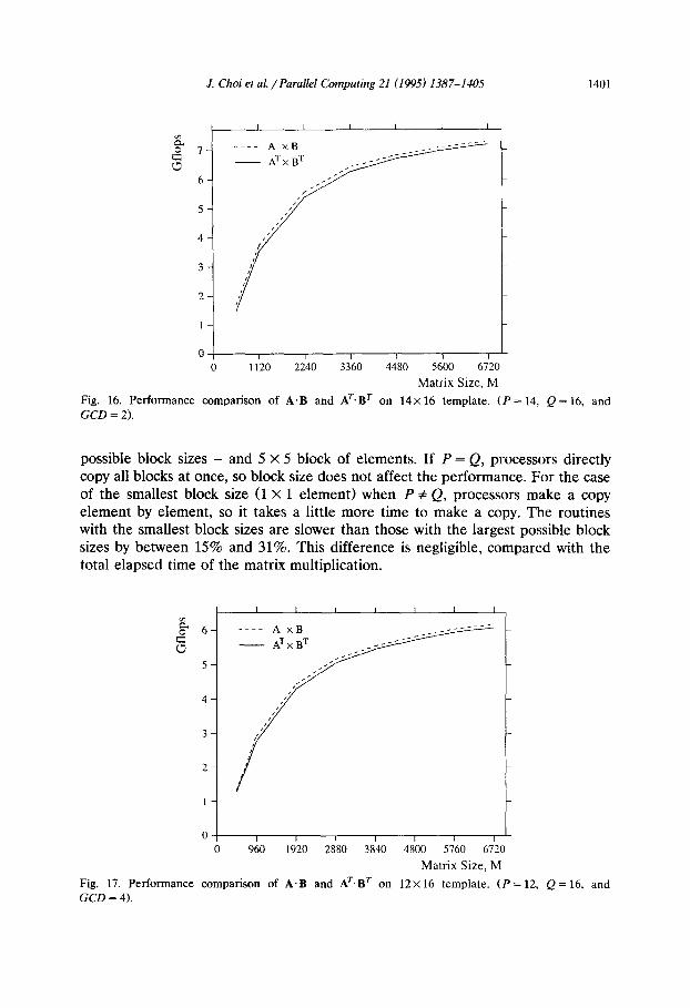
Fig. 16. Performance comparison of A.B and AT.BT on 14x16 template. (P = 14, Q = 16, and GCD = 2).
possible block sizes - and 5 X 5 block of elements. If P = Q, processors directly copy all blocks at once, so block size does not affect the performance. For the case of the smallest block size (1 X 1 element) when P # Q, processors make a copy element by element, so it takes a little more time to make a copy. The routines with the smallest block sizes are slower than those with the largest possible block sizes by between 15% and 31%. This difference is negligible, compared with the total elapsed time of the matrix multiplication.
00 0 960 1920 2880 3840 4800 5760 6720
Matrix Size, M
Fig. 17. Performance comparison of A.B and AT.BT on 12x 16 template. (P = 12, Q = 16, and GCD = 4).

1402 J. Choi et al. /Parallel Computing 21 (1995) 1387-1405
g. 4
8
3
2
I
0 + I I I I I I -l- 0 800 1600 2400 3200 4COO 4800 5600
Matrix Size, M
Fig. 18. Performance comparison of A.B and AT.BT on 8 X 16 template. (P = 8, Q = 16, and GCD = 8).
Performance per node is shown in Table 3. The 1 x 1 template gives the performance of the assembly-coded level 3 BLAS matrix multiplication routine for the two cases A. B and AT. BT. Processors have about 85% efficiency for A - B, and 87% for AT * BT if P = Q = 16. The routines perform better on templates for which P # Q. Processors achieve about 89% and 93% of efficiency for each case if P and Q are relatively prime.
0 I I I I I 0 1600 3200 4800 6400 8000
Matrix Size, M
Fig. 19. Performance comparison of A.B and AT.BT on 16 x 16 template. (P = Q = GCD = 16).

J. Choi et al. /Parallel Computing 21 (1995) 1387-1405 1403
Table 2 Dependence of performance on block size
PxQ Matrix size
8X16 4800 x 4800
12x 16 4800x4800
14x 16 5600 x 5600
15x16 6000 x 6000
16X16 6400x6400
Block size Time (second)
1x1 1.857
.5X5 1.612
300 x 300 1.564
1x1 1.280
5X.5 0.893
100x 100 0.882
1x1 1.484
5x5 1.193
50x50 1.161 1x1 1.740
5x5 1.437 25x25 1.426
1x1 1.967
5x5 1.961
400 x 400 1.967
5. Conclusions and remarks
We have presented parallel matrix transpose algorithms based on the block cyclic data distribution. The algorithms have good performance for arbitrary processor configurations on the Intel Delta computer.
If P and Q are relatively prime, the transpose routine involves complete exchange communication on a two-dimensional template. We have approached this complicated problem with a direct point-to-point communication scheme (see Section 2). When P and Q are not relatively prime (GCD > l), the processors’ operations are overlapped over different groups, so that only LCM/GCD commu- nications are required.
In our Fortran implementation, we assume that the first dimension of the matrix may be different from the number of rows of the matrix in a processor. Even when P = Q, the processor needs to copy blocks of A to a communication buffer before sending, and copy the received buffer to blocks of C after receiving.
Table 3 Performance per node in Mflops. Block size is fiied to 5 x 5 elements. 1 X 1 template gives performance
of assembly-coded matrix multiplication. Numbers in parentheses represent efficiency compared with
the performance on 1 processor
PxQ Matrix size (A, B) A.B (%) AT.BT (%I
1x1 500 x 500 36.70 (100.0) 35.04 (100.0) 8X16 5600 x 5600 32.05 (87.3) 30.57 (87.3)
12x16 6720 x 6720 32.09 (87.4) 31.64 (90.3) 14x16 6720 x 6720 32.52 (88.6) 32.11 (91.6) 15x16 7200~7200 32.78 (89.3) 32.43 (92.6) 16X16 8000x8000 31.22 (85.1) 30.38 (86.7)
1404 J. Choi et al. /Parallel Computing 21 (1995) 1387-1405
The parallel matrix transpose algorithms have been combined with matrix multiplication routines. The integrated routines comprise a general-purpose matrix multiplication package, called PUMMA [5], for MIMD message-passing comput- ers. The package has good performance for a wide range of decomposition parameters, that is, its performance depends weakly on processor configuration and block size.
The PUMMA package is currently available for all numeric data types, i.e., single and double precision real and complex. To obtain a copy of the software and a description of how to use it, send the message, ‘send p umm a f r om s c a L a-
pack’to [email protected].
Acknowledgments
The authors would like to thank Eduardo D’Azevedo at ORNL for his helpful suggestions to improve the quality of the paper. This research was performed in part using the Intel Touchstone Delta System operated by the California Institute of Technology on behalf of the Concurrent Supercomputing Consortium. Access to this facility was provided through the Center for Research on Parallel Computing.
References
[l] N.G. Azari, A.W. Bojanczyk and S.-Y. Lee, Synchronous and asynchronous algorithms for matrix transposition on MCAP, in: SPIE Vol. 975, Advanced Algorithms and Architecture for Signal Processing III (1988) 277-288.
[Z] S.H. Bokhari and H. Berryman, Complete exchange on a circuit switched mesh, in: Proc. Scalable High Performance Computing Conf (IEEE Press, 1992) 300-306.
[3] J. Choi, J.J. Dongarra, R. Pozo and D.W. Walker, ScaLAPACK: A scalable linear algebra library for distributed memory concurrent computers, in: Proc. Fourth Symp. on the Frontiers of Massively Parallel Computation @IcLean, Virginia1 (IEEE Computer Society Press, Los Alamitos, CA, Oct. 19-21, 1992).
[4] J. Choi, J.J. Dongarra and D.W. Walker, The design of scalable software libraries for distributed memory concurrent computers, in: Proc. Environment and Tools for Parallel Scientific Computing Workshop (Saint Hilaire du Touuet, France) (Elsevier Science, Sept. 7-8, 1992).
[5] J. Choi, J.J. Dongarra and D.W. Walker, PUMMA: Parallel universal matrix multiplication algorithms on distributed memory concurrent computers, Concurrency: Practice and Experience 6 (1994) 543-570.
[6] J.J. Dongarra, R. van de Geijn and D. Walker, A look at scalable linear algebra libraries, in: Proc. 1992 Scalable High Performance Computing Conf (IEEE Press, 1992) 372-379.
[7] J.O. Eklundh, A fast computer method for matrix transposing, IEEE Trans. Comput. 21 (1972) 801-803.
[8] G.H. Golub and C.V. Van Loan, Matrix Computations (The Johns Hopkins University Press, Baltimore, MD, 1989) second ed.
[9] Intel Corporation, Touchstone Delta Fortran Calls Reference Manual (April 1991). [lo] S.L. Johnsson and C.-T. Ho, Algorithms for matrix transposition on boolean n-cube configured
ensemble architecture, SOlM J. Matrix Anal. Appl. 9 (July 1988) 419-454.

J. Choi et al. /Parallel Computing 21 (1995) 1387-1405 1405
[ll] R. Littlefield, Characterizing and tuning communications performance for real applications, in:
Proc. First Intel Delta Application Workshop, CCSF-14-92, Pasadena, CA (Feb. 1992, presentation
overheads) 179-190.
[12] D.P. O’Leary, Systolic arrays for matrix transpose and other reorderings, IEEE Trans. Comput. 36 (Jan. 1987) 117-122.
[13] G. Strang, Linear Algebra and Its Applications (Harcourt Brace Jovanovich, San Diego, CA. 1988)
third ed.
[14] S. Takkella and S.R. Seidel, Complete exchange and broadcast algorithms for meshes, in: froc.
Scalable High Performance Computing Conf. (IEEE Press, 1994) 422-428.