Parallax Suppression with a Target Rifle Aperture...
23
Parallax Suppression with a Target Rifle Aperture Sight Robert J. Burdge and Douglas A. Kerr, P.E. Issue 4 May 30, 2007 ABSTRACT With an aperture sight, often used on target rifles, the shooter looks through a small hole in a metal plate that is mounted on the rear of the rifle near the shooter’s eye, observes a front sight which is typically a small vertical post located near the front of the barrel, and adjusts the aim of the rifle until the top of that post is located on the desired location on the target. Additionally, users of these sights are always urged to position their eye so that the tip of the post is positioned precisely in the center of the field of view observed through the rear sight aperture. This is done in the interest of eliminating parallax shift between the front sight and target which would lead to uncertainty in aiming. But we find that, as we look through such a sight and move our eye from side to side (with the aiming point of the rifle fixed), we see essentially no change in the relative position of the tip of the front sight and the target. The expected effect of parallax shift does not appear. This suggests that sight alignment, in the traditional sense, does not affect the point of aim. In this article we look into this phenomenon. In the process, we will encounter various related matters in the fields of photographic optics and human vision. The results of both “live fire” and optical model tests are given and discussed. An appendix presents a ray tracing exercise that demonstrates the phenomenon and its source. THE APERTURE SIGHT Description An aperture sight (sometimes called a “peep sight”), often used on target rifles, comprises a rear sight, which is essentially a metal plate with a small circular hole in it (with a typical diameter of 1.0-1.5 mm), mounted near the rear of the receiver, and a front sight, which is a small vertical post (perhaps 1-2 mm wide) near the muzzle of the barrel. Here we see a typical basic aperture sight installation.
Transcript of Parallax Suppression with a Target Rifle Aperture...

Parallax Suppression with a Target Rifle Aperture Sight
Robert J. Burdge and Douglas A. Kerr, P.E.
Issue 4 May 30, 2007
ABSTRACT
With an aperture sight, often used on target rifles, the shooter looks through a small hole in a metal plate that is mounted on the rear of the rifle near the shooter’s eye, observes a front sight which is typically a small vertical post located near the front of the barrel, and adjusts the aim of the rifle until the top of that post is located on the desired location on the target. Additionally, users of these sights are always urged to position their eye so that the tip of the post is positioned precisely in the center of the field of view observed through the rear sight aperture. This is done in the interest of eliminating parallax shift between the front sight and target which would lead to uncertainty in aiming.
But we find that, as we look through such a sight and move our eye from side to side (with the aiming point of the rifle fixed), we see essentially no change in the relative position of the tip of the front sight and the target. The expected effect of parallax shift does not appear. This suggests that sight alignment, in the traditional sense, does not affect the point of aim.
In this article we look into this phenomenon. In the process, we will encounter various related matters in the fields of photographic optics and human vision. The results of both “live fire” and optical model tests are given and discussed.
An appendix presents a ray tracing exercise that demonstrates the phenomenon and its source.
THE APERTURE SIGHT
Description
An aperture sight (sometimes called a “peep sight”), often used on target rifles, comprises a rear sight, which is essentially a metal plate with a small circular hole in it (with a typical diameter of 1.0-1.5 mm), mounted near the rear of the receiver, and a front sight, which is a small vertical post (perhaps 1-2 mm wide) near the muzzle of the barrel. Here we see a typical basic aperture sight installation.

Parallax Suppression with a Target Rifle Aperture Sight Page 2
Figure 1. Typical aperture sight
The shooter looks through the aperture in the rear sight (with the eye perhaps 40 mm behind the sight), observes the front sight, and aims the rifle until the top of the post is located on the desired location on the target.1
Averting parallax shift—the conventional wisdom
Although the rear sight aperture is quite small in diameter, because the eye position is fairly close to it, the field of view seen through the aperture is fairly wide. Differences in eye position behind the aperture will result in the tip of the front sight being seen at different locations within that field. Conventional wisdom holds that this leads to different points of aim. This is attributed to the well-known phenomenon of parallax shift2.
Users of these sights are often urged to strive for an eye position that puts the apparent location of the top of the front sight in the center of the field of view seen through the rear sight. This is described as “maintaining proper sight alignment”.
1 In a typical target shooting setting, the target is a dark circular disk, whose apparent size is very nearly the same as the apparent width of the front sight post, and the rifle is “sighted in” so that the appropriate aiming situation is with the target apparently “sitting just on the top of” the front sight post.
2 Parallax shift, in this context, can be thought of as a change in the apparent alignment of two objects, at different distances from the observer, as the point from which the scene is viewed is changed.

Parallax Suppression with a Target Rifle Aperture Sight Page 3
The width of the front sight typically subtends an angle similar in size to the target, on the order of 6 minutes of arc (MOA). By contrast, the field of view through the rear aperture (for the case of a 1 mm aperture and 30 mm of eye relief3) is approximately 1.9 degrees (or 115 MOA). Thus the width of the target and front sight only cover about 5% of the width of the field of view. This can make precisely centering the front sight within the aperture seem like a daunting task prone to error.
A common admonition to novices using aperture sights, concerned with the need to make this alignment, is that “the eye will naturally center the post in the aperture”. Still, much effort is usually spent insuring proper centering of the front sight.
This figure illustrates the recommended “sight alignment” (centering of the front sight post tip in the field of view of the rear sight) and “sight picture” (target atop the front sight and centered with it).
Figure 2. Recommended sighting situation
Parallax shift—the reality
In actual practice, we find that if we look through an aperture sight, with the aim of the rifle fixed (perhaps it is held in a sighting vise), and move our eye from side to side, we see almost no change in the relative locations of the tip of the front sight and the target (what shooters call the “sight picture”). Essentially, the phenomenon of parallax shift does not appear.
On the other hand, if, as a “check” on our observations, we raise our eye so that we look completely over the rear sight, and adjust the pointing of the rifle so that again the tip of the front sight aligns with the target, we find that when we move our eye from side to side by the same amount we did before, we do see a definite shift in the relative locations of the tip of the front sight and the target. This is in fact parallax shift at work.
3 The distance the eye is behind the rear sight.
Parallax Suppression with a Target Rifle Aperture Sight Page 4
What is happening here? Does the simple rear sight have some power to suppress the effect of parallax shift? Well, yes. We will shortly find out how this works.
OPTICAL BACKGROUND
First, a little background on some optical principles that are involved.
The entrance pupil
In photographic optics
In photographic optics, we draw heavily on the concept of the entrance pupil of a lens. This is defined as the virtual image, from in front of the lens, of the aperture stop. The aperture stop is an opaque plate with an opening, which serves to “throttle” the light entering the lens as a component of obtaining proper exposure. Typically, the size of this opening can be varied, today usually with an “iris” arrangement. In all but primitive box cameras, the aperture stop is located inside the lens—between certain of its elements.
If we look into a typical camera lens from the front, we can usually see the iris. But of course we don’t really see it. What we see is its virtual image, created by the working of the lens elements in front of the stop. What we see may not be the same size, nor in the same location along the lens axis, as the physical aperture stop. But it is, by definition, the entrance pupil.
The entrance pupil has two significances to us. First, it is the port through which the lens collects light, and its size thus influences exposure. Secondly it is the “peephole” through which the camera sees the world and its location thus determines the camera’s “point of perspective” (as we will discuss shortly).
In the human eye
The concept of the entrance pupil is directly applicable to the human eye. Again, we have here an “iris” mechanism (from which the ones used in photography take their name!), and its virtual image from the front of the eye (as it is seen through the eye’s lens) is the eye’s entrance pupil.
The human visual system automatically varies the size of the opening in the iris (and thus the size of the entrance pupil) in order to accommodate the wide range of scene luminance (brightness) in which the eye must function, rather like automatic exposure control in a camera. Typically for the brightest scene environment the diameter of the entrance pupil is about 2 mm, and for the darkest scene (perhaps complete darkness), the diameter is about 8 mm.

Parallax Suppression with a Target Rifle Aperture Sight Page 5
The point of perspective
When we deal with parallax matters, we are concerned with the vantage point from which our camera, or a human eye, or a human eye plus a rifle sight, views the scene. This is called the point of perspective of the optical system, and in fact is important not only to matters of parallax but also of perspective itself (which we won’t be dealing with here).
If we consider direct human vision (one-eyed), in a large view of life, it is not hard to decide where the point of perspective is. It is “where the eye is”.
But as we consider such things as small eye movements and the precise alignment of small objects, we have to get more specific. Then, we normally treat the center of perspective as being at the center of the eye’s entrance pupil.
This at first seems a little over-simplistic. After all, the eye doesn’t just regard the world through the center of the entrance pupil, but rather through all of it. So shouldn’t we consider that the eye has many “vantage points”, one for every imaginable location within the entrance pupil? Absolutely. But how can we deal with this in optical calculations and the like?
To help us grasp this dilemma, let’s do a little thought experiment on parallax. Imagine that in front of our eye, at a distance of, say, 10 inches, we have a vertical pencil. Behind that, at a distance of say 20 inches, we have a vertical fat stick of chalk. A plane passing through the axis of these two cylinders also passes through the center of the entrance pupil of our eye. Thus we can say, simplistically, that the two cylinders are aligned from a vantage point at the center of the entrance pupil.
But recalling that the entrance pupil has a substantial size, doesn’t the eye really see multiple images from different vantage points all across the entrance pupil: one image in which the two cylinders are aligned, and many other images in which they are misaligned by differing amounts in various directions?
Quite so.
Now suppose that the eye is precisely focused on the pencil. For our present purpose, we can look at this as meaning that multiple images of the pencil (which we can think of as being observed from multiple vantage points across the entrance pupil) all coincide on the eye’s retina, and thus form a unitary image of the pencil, which we consider to be sharply focused.

Parallax Suppression with a Target Rifle Aperture Sight Page 6
Now what about the chalk? The eye is not precisely focused on it. That means that the multiple images of the chalk, (which again we can think of as being observed from multiple vantage points across the entrance pupil), do not coincide on the eye’s retina. Thus, they collectively form a spread out, or blurred, image of the chalk.
But we still must ask, “are the images of the pencil and the chalk aligned”? Suppose that the (sharp) image of the pencil seems centered between the (blurred) left and right outlines of the (blurred) image of the chalk. Thus we conclude, “yes, the pencil and chalk are aligned”. That finding is of course consistent with the concept that the point of perspective must be considered to be at the center of the entrance pupil.
BACK TO OUR APERTURE SIGHT
The rear sight of the aperture sight and the shooter’s eye collectively form an optical system. What is its entrance pupil? Well, there are two candidates. One is the entrance pupil of the eye, and indeed no light can enter the eye except through it, and no part of the scene not visible through it can be observed. The second entrance pupil is the aperture of the rear sight. Again, no light (at least none relevant to looking at the front sight) can enter the eye except through it, and no part of the scene not visible through it can be observed. In fact, it is the common area of the two individual entrance pupils (their geometric “intersection”) that becomes the entrance pupil of our optical system.
Assume for the moment that the sight aperture is smaller than the eye’s entrance pupil and is located wholly within it (but not necessarily centered within it). Thus the intersection of the two pupils is the sight aperture alone, and it is our entrance pupil.
Where is the point of perspective of this optical system—the location from which it seems to view the scene? At the center of the entrance pupil, which we have just concluded is the sight aperture.
Now, if we move our eye from side to side a little bit, our first thought is that the point of perspective would change. But since the point of perspective is at the center of the sight aperture, and that is fixed, the point of perspective does not move.
And this is why there is essentially no manifestation of parallax shift with modest amounts of eye movement in an aperture sight.
One of the authors (Burdge), who first noticed this phenomenon, has dubbed this the “parallax suppression” afforded by an aperture sight.
Incidentally, this parallax suppression is similar in nature to that provided by the more complex AimPoint sight used by the military

Parallax Suppression with a Target Rifle Aperture Sight Page 7
(without the added benefit of the single focal plane that sight provides, of course). With the AimPoint sight, the location of the aiming dot within the sight does not affect the Point of Impact, and the sight is considered “parallax free”. But we see now that we enjoy this same benefit in the basic aperture sight.
EXTENDED EYE MOVEMENT
If we move the eye more than a certain amount, the edge of its entrance pupil begins to encroach on the sight aperture. We now have a new entrance pupil, the geometric intersection of our two individual pupils, no longer circular and with its center no longer at the center of the sight aperture.
As this happens, the point of perspective does move, and parallax shift begins to appear. However, the total movement of the center of perspective is not as great as the total movement of the eye. Thus, although we no longer have full parallax suppression, we have parallax reduction.
EFFECT OF ENVIRONMENTAL BRIGHTNESS
The brightness (luminance) of the environment, of course, affects the diameter of the eye’s entrance pupil. Thus in a darker environment the amount of eye shift permissible before parallax suppression degrades into parallax reduction is greater than in a brighter environment.
Typically, the rear of the rear sight has a dull black finish, said to reduce “glare” and to enhance the contrast with which the front sight and the target are seen. But fortunately, this also reduces the average brightness seen by the eye, and causes the eye’s pupil to enlarge. This of course enlarges the range of eye movement for which we have full parallax suppression.
In some precision sights, this effect is enhanced by way of an “eye cup” surrounding the aperture disk proper.
DECREASE IN TARGET BLURRING
In a camera, if we decrease the size of the aperture, we increase the “depth of field”—the range of object distances, surrounding the distance for which perfect focus is attained, for which the object will be imaged with what we choose to consider “negligible” blurring. Looking at this from the other direction, if we decrease the size of the aperture, we decrease the amount of blurring for an object at some particular distance that is not the distance of perfect focus.
Similarly, when we use an aperture sight, and the sight aperture takes over the role of entrance pupil from the entrance pupil of the eye,

Parallax Suppression with a Target Rifle Aperture Sight Page 8
reducing the size of the entrance pupil, we enjoy reduced blurring of the target (assuming perfect focus on the front sight post).
LIVE FIRE EXPERIMENT
To support the conclusions set forth in this paper a live fire experiment was recently conducted by one of the authors (Burdge). A suitable target was positioned at a distance of 100 yards on a range and fired at with the front sight positioned in various locations within the rear aperture’s field of view by choice of eye position.
The actual targets resulting from the different stages of the test are illustrated on the following page. To the left of each target is an illustration of the “sight picture” used to aim the rifle while shooting the group.
The first target shows the results of 5 shots fired at the target with the front sight carefully centered within the aperture.
The second target shows the result for a group fired with the front sight intentionally offset towards the upper edge of the aperture. The “ears” of the front sight were positioned so that they were near the edge of the aperture. This magnitude of offset constitutes a “gross misalignment” of the sights in terms of the standard method of aiming, and under the “common wisdom” would be expected to result in shots that would be displaced from the intended point of aim by a considerable amount because of parallax. However, as can be seen from the target, this “misalignment” of the front sight in the aperture did not result in a significant shift of the bullet group on the target.
The third target shows the result for a group fired with the front sight intentionally offset towards the left edge of the aperture. The left “ear” of the front sight was aligned near the edge of the aperture. Once again it would be expected that this amount of offset would move the shot far from the intended point of aim.
In this example a small amount of leftward shift of the group is noticed. This is most likely the result of one of two causes, or both. It is possible that the sight alignment was too severe, and the front sight strayed outside of the zone of full parallax suppression. The edge of this zone is noticeable since the brightness of the image begins to reduce. It is also possible that it was caused by a slightly different “hold” on the rifle by the person conducting the firing test.

Parallax Suppression with a Target Rifle Aperture Sight Page 9
Figure 3. Results of live fire test

Parallax Suppression with a Target Rifle Aperture Sight Page 10
Each target also appears to have a “flyer” that is probably attributable to the first shot being fired from a cold barrel. In hindsight, a more thorough test would have used a “fouling” shot off-target prior to each group being fired.
OPTICAL MODEL TESTS
One of the authors (Kerr) conducted a series of tests with an optical model to allow visualization of the effects we describe here. It is based on a 4x scale mockup of a rifle aperture sight system. A digital camera plays the role of the shooter’s eye. The test apparatus allows calibrated shift of the “eye” position, and the camera images reflect what the shooter would see, including the impact of any parallax shift.
A complete description of the test apparatus and procedure, along with an extensive set of test images and a discussion of their implication, will be found in a companion paper.4
Here we will present just a few of the images, which serve to clearly illustrate both the appearance of parallax shift and its suppression or reduction by the workings of the aperture sight.
In the discussion to follow, all dimensions are given in terms of what they represent in “real life” scale. (All actual dimensions are 4 times this).
In our dummy sight, the rear sight aperture has a diameter of 1.0 mm, and the width of the front sight post is also 1.0 mm. The diameter of the eye’s entrance pupil (that is, the entrance pupil of the camera lens) can be varied with the aperture control for the lens.
The target comprises a simple black aiming circle whose diameter was chosen so that (at the distance of the target used in the test) the diameter of the target appears essentially the same to the shooter as the width of the front sight post.
For each round of tests, we first align the rig so it represents ideal sight alignment (eye position): the center of the tip of the front sight post falling in the center of the field of view through the rear sight. Then the “rifle” is aimed at the target following the classical “pumpkin on a post” sight picture.
One test shot is taken in this initial situation. Then, the camera (our “eye”) is moved leftward in increments of 1/8 mm, with a test shot
4 Parallax Suppression with a Target Rifle Aperture Sight—An Optical Demonstration, Douglas A. Kerr, P.E., Issue 1, May 29, 2007, published online at The Pumpkin: http://doug.kerr.home.att.net/pumpkin/index.htm#ApertureSightDemo

Parallax Suppression with a Target Rifle Aperture Sight Page 11
being taken at each position. This is continued until the images of the target disk and sight post essentially “fall out of” the field of view.
Since the rifle aim is constant, any misalignment between the centerlines of the front sight post and the target disk is a manifestation of parallax shift. Of course in an actual shooting situation, the shooter would shift the aim of the rifle to bring the front sight post and target disk together, leading to an erroneous pointing direction because of the parallax shift.
In addition, a similar series of tests was taken with the rear sight plate totally removed. In this case, the entrance pupil of the entire optical system becomes the entrance pupil of the camera (“eye”), and the point of perspective falls there. Thus, as the eye moves, so does the point of perspective, leading to parallax error (the same parallax error that common wisdom says we can expect from eye position movement with an aperture sight). Images from this round of tests show this parallax shift (which, fortunately, we do not actually encounter).
The tests illustrated here are with an eye pupil diameter of 4.2 mm (which we might expect for a human eye in “moderate” outdoor light).
In the two panels below, the upper figures show the result of the tests with the actual sight system They show first the situation with “ideal” sight alignment and then for an eye shift to the left of 0.25 mm, 0.75 mm, 1.25 mm, 1.50 mm, and 2.00 mm.
Below each image is an image showing the “unmitigated” parallax shift we can experience by removing the rear sight plate—the parallax shift we would suffer from were it not for the phenomena of parallax suppression and parallax reduction.
To facilitate comparison, these lower images have been artificially “vignetted” to a scope corresponding to the field of view that would actually be seen through the rear sight for the same eye position (as seen in the upper images).

Parallax Suppression with a Target Rifle Aperture Sight Page 12
Rear sight in place Ideal eye position
Rear sight in place Eye shift left 0.25 mm
Rear sight in place Eye shift left 0.75 mm
Rear sight out
Ideal eye position Rear sight out
Eye shift left 0.25 mm Rear sight out
Eye shift left 0.75 mm
Note that even with an eye shift of 0.75 mm, no parallax shift is evident in the actual sight situation, while a substantial parallax shift would be evident were there no parallax suppression at work in our favor.
Now we will continue to greater eye shifts (on the next page).

Parallax Suppression with a Target Rifle Aperture Sight Page 13
Rear sight in place
Eye shift left 1.25 mm Rear sight in place
Eye shift left 1.50 mm Rear sight in place
Eye shift left 2.00 mm
Rear sight out
Eye shift left 1.25 mm Rear sight out
Eye shift left 1.50 mm Rear sight out
Eye shift left 2.00 mm
We see that as the eye shift reaches 1.50 mm, a small amount of parallax shift appears. This is the beginning of the transition from parallax suppression to parallax reduction. It occurs just about where theory predicts.
Of course, the amount of parallax shift for even an eye shift of 2.00 mm is considerably less than were there no parallax reduction. This eye shift is the greatest we can incur here; for any more, we could no longer see the front sight post through the rear sight.
ADVICE TO THE SHOOTER?
Should shooters ignore the urgings to scrupulously position the eye so that the front sight post appears to be in the center of the field of view of the rear sight aperture?
Well, yes, and no. We find that precise centering of the front sight within the rear aperture is not required to guarantee a precise aim.
Centering does promote a consistent head position, though, which is known to be important to accuracy because of its affect on how the
Parallax Suppression with a Target Rifle Aperture Sight Page 14
rifle behaves during recoil and the changes in the point of impact that can result. However, as a practical matter, the amount of head movement involved in moving the front sight within the field of view is very small (less than 1 mm), and is not likely to be a significant factor.
With the front sight and target positioned near the extremes of the field of view, the light from these objects enters the eye off-axis from the center of the pupil. Depending on aberrations in the lens of the shooters eye, this could cause image distortion compared to light entering the pupil through its center. It is equally possible that some people could experience an improvement in sight picture if the center of their vision has aberrations.
THE PRACTICAL BENEFIT
The practical benefit to the target shooter from this new insight is how it affects the shot process. By allowing shooters to spend less time and attention on centering the sight picture within the aperture, the aiming process can be executed more quickly. This reduces the risk of “retinal burn-in” which can result from staring at the sights too long. The after image formed from retinal burn-in can be a serious source of aiming error since it fools the shooter into aiming incorrectly by producing a false image of where the sight and target are located.
Shooters have many things to concern themselves with during the execution of a shot. These include aiming, maintaining a natural point of aim, trigger technique, breathing, and wind estimation. By removing an item from the work load on the shooter’s list (and removing what is sometimes erroneously identified as a source of off-shot calls), the available time can be better spent concentrating on the tasks that make a difference.
There is also a similar practical benefit for any individual who uses a weapon equipped with aperture sights during life-and-death circumstances, particularly members of our Armed Forces and law enforcement agencies. Individuals fall back on training when confronted with a stressful situation. Training today includes an emphasis on establishing proper sight alignment before taking a shot. By reducing this emphasis, the shooter can gain a precious moment of time that may save his life.
DEMONSTRATION BY RAY TRACING
In Appendix A, “ray-tracing” diagrams are given that graphically illustrate how and why the situation reported here occurs.
ACKNOWLEDGEMENT
Thanks to Carla Kerr for her skilled copy editing of this manuscript.

Parallax Suppression with a Target Rifle Aperture Sight Page 15
ABOUT THE AUTHORS
Robert J. Burdge is an Electrical Engineer employed with Garmin International, Inc. in Olathe, Kansas, where he designs avionics equipment. He is an avid competitor in the sport of NRA Highpower target shooting and a life-long un-licensed “tinkerer”.
Douglas A. Kerr, P.E., is a consulting telecommunication engineer in private practice, now mostly retired, located in Dallas, Texas. His ongoing interest in optical theory has been linked to his interest in photographic technology. In recent years he has written a number of articles discussing the application of various points of optical theory to photographic practice (especially in the arena of digital photography).
#

Parallax Suppression with a Target Rifle Aperture Sight Page 16
APPENDIX A
Ray Tracing Demonstration
Douglas A. Kerr, P.E.
In this appendix, we use a simple form of ray tracing to demonstrate how and why parallax suppression occurs in an aperture sight.
Ray tracing
Ray tracing is a technique used in optical system investigation in which we plot the expected path of certain light rays of interest as they pass through lens elements, apertures, and other components of the optical system of interest.
Formal ray tracing deals with the actual detailed composition of the optical system. It considers what happens to each ray of interest as it meets each glass-to-air (or glass-to-another-kind-of-glass) interface. It is normally done numerically, based on Snell’s law, which describes the refraction of a ray at an interface.
Often various simplifications are adopted to reduce the labor of a full-blown numerical ray training exercise.
The thin lens
Often, the basic behavior of a lens can be easily analyzed by using the “thin lens fiction”. This says that the overall path of a ray through a lens can be treated as if the ray were refracted only once, at a plane in the center of the lens. In real life, the surface curvature lens of a lens becomes less and less, it becomes thinner and thinner, and the actual behavior approaches that of the fanciful ”thin lens”. Ironically, the lens only fully attains this ideal situation when the curvature reaches zero and thus the lens has no refractive effect at all.
The chief ray
Nevertheless, the thin lens fiction can be useful to us in allowing a simplified form of ray tracing. This form of ray tracing depends on an important principle of optical behavior. Any ray that arrives at the lens along a path that passes through the center of the lens (meaning the center in the sense of across the lens and also in the sense of being at the center of its thickness) will not be refracted (bent), but will rather continue through the lens along that same path. A ray from a particular point on the “object” that meets this criterion is called the chief ray or principal ray from that point.

Parallax Suppression with a Target Rifle Aperture Sight Page 17
Ideal lens behavior
In our work here, we will not only exploit the “thin lens fiction” but will also assume that the lens is free of any aberrations but instead exhibits various ideal properties. Two of these ideal properties (not fully enjoyed by any simple real lens) are:
• All rays from any point on an object that pass through the lens are brought together at a single point beyond the lens (the “image” of the object point).
• If the object comprises points all in a plane, then the images of all the points of the object will also fall in a plane.
The human eye
The human eye is a unique optical system. Since our work here is based on the use of the human eye, we must somehow represent the human eye in our ray tracing model. Doing so directly is quite daunting. For one thing, in the human eye, the retina (which of course takes the place of the film in a camera) is substantially curved (almost a portion of a sphere). For another, the material that fills the space between the lens and the retina (the vitreous humor) has essentially the same index of refraction as the lens proper. In effect, the lens (in the optical engineering sense) extends all the way to the retina. (Imagine a camera whose body was filled with glass!)
Here, we will dodge these complications, and replace the eye with a basic camera-like structure, with a thin lens, a flat retina 26.0 mm behind the lens, and air between. This will allow us to most clearly see the principle of interest.
Regarding the entrance pupil of the human, eye, its diameter varies with the ambient illumination (part of the eye’s crafty “automatic exposure control”). In very bright light, the diameter is typically 2 mm; in very dim light, perhaps 8 mm. Here, we show the entrance pupil of the eye as being 4 mm, hopefully representative of a reasonable actual situation for outdoor shooting (the rear sight itself helps to shield the eye from the full impact of the ambient brightness).
THE PARAMETERS OF OUR MODEL
The model of a rifle sight and shooter’s eye used for our ray tracing exercise has the following parameters:
• Distance to the target: “Great” (treated as infinite from an optical theory standpoint)
• Width of the front sight post: 1.0 mm

Parallax Suppression with a Target Rifle Aperture Sight Page 18
• Diameter of the target disk: Such that its apparent (angular)
diameter is the same as the apparent width of the front sight post (reckoned from the center of the “eye” lens)
• Diameter of the rear sight aperture: 1.0 mm
• Sight radius (distance between front and rear sights): 600 mm (about 23.6”)
• Eye relief (distance between the rear sight and the eye lens): 40 mm (about 1.6”)
• Distance (in the stand-in for the human eye) between the thin lens and the “retina”: 26.0 mm.
• Diameter of the eye’s entrance pupil: 4.0 mm
The shooting situation
Our work assumes a situation in which:
• The shooter precisely focuses his eye on the front sight post.
• With the shooter’s eye exactly centered within the rear sight aperture, the rifle is aimed so that the front site post appears laterally centered within the width of the target disk.
• Then, with that aim of the rifle held, the shooter’s eye is moved to the right by 0.4 mm.
Our interest
Our interest is in determining the degree to which, after the eye is moved, the images of the front sight post and the target disk are no longer aligned (a manifestation of “parallax shift”).
THIS RAY TRACE EXERCISE
The rays of interest
In our ray trace exercise, we follow the paths of four light rays from each of the two “objects”: the front sight post and the target disk. For each object, two of those rays come from a point on the far right side of the object and two from a point on the far left side. The two rays from a each point are the “widest-spread” ones that can enter our optical system, grazing the right and left edges of the applicable entrance pupil.
We follow these rays until they approach and then strike the retina, where we consider the nature and location of the images they form.

Parallax Suppression with a Target Rifle Aperture Sight Page 19
Implications of focus
We assume that the shooter has focused his eye “perfectly” on the front sight post. That means that the rays from each point on the post (we only treat two rays from each of two points) converge precisely on the retina, producing a sharp image of that point (and thus, over all points on the post, a sharp image of the post). It turns out that for our setup parameters, this requires that the focal length of the lens be 25.0 mm (essentially, the eye makes its lens have that focal length so it will focus on the post), and we will proceed on that basis.
With respect to the rays from the target disk, the rays from each point indeed converge behind the lens, but at a different distance (owing to the different distance to this object). Since the target disk is “at infinity”, that occurs at a distance equal to the focal length of the lens (25.0 mm) behind the center of the lens. At that location (1 mm in front of the retina), a sharp “aerial image” is formed, but we don’t “see” it, since there is no retina there to “pick it up”.
The rays from each point of the target disk, having converged at the plane of the aerial image, continue on toward the retina (spreading apart as they go), and when they hit the retina, land all over a circular region, forming what is called a blur figure, or circle of confusion. The collection of these blur figures produced from all the points across the entire object gives a “blurred” image of the object on the retina. If we consider the edges of the object (as we do in this discussion), each edge is “thickened” to a width equal to the diameter of the blur figure.
Our ray trace figures will let us see this happening.
Scaling of the vertical axis
With the parameters we have adopted for this model (realistic for the situation of interest), the angles involved are very small. For example, the total angle subtended by the front sight post (from the center of the eye lens) is about 5.4 minutes of angle (MOA).
One result of this is that a ray trace plot to real scale would be extremely hard to grasp visually. A secondary result is that this strains the ability of the computer program (used to do the dog work for the plot) to locate precisely the intersection between two lines.
Accordingly, we plotted our ray trace exercises on a grid in which the vertical scale is exaggerated by a factor of 20. The results are unaffected by this (except of course in how they look).
Now, can we see the pictures?
Because of the relative proportions of our model, we will need to approach ground zero in stages. This shows the entirety of two plots.

Parallax Suppression with a Target Rifle Aperture Sight Page 20
Figure 4. Overview of the ray trace plots
Panel A shows our model, with the eye offset by the amount mentioned above, but with the rear sight taken away. This situation allows the phenomenon of parallax shift to occur. Perhaps more importantly, this will demonstrate the ability of this type of plot to show that parallax shift. Panel B shows the same model with the rear sight in place. We will look to it to see if the phenomenon of “parallax suppression” is demonstrated.
Of course, the scale of this figure here makes it impossible to see any detail. It is presented just to give the reader a visual grasp of the proportions that are involved.
The view is from the top, so that up corresponds to right in the real world.
Note that the front sight post is presented in green and we can think of the target disk (off the drawing, of course) as being blue.
In the next figure, we have zoomed in so that we can begin to see the various rays that are involved.
The rays from the front sight post are shown in green and those from the target disk in blue.

Parallax Suppression with a Target Rifle Aperture Sight Page 21
Situation A Situation B
Figure 5. Convergence of the rays
Now, we will really zoom in on the area where the images are formed. Here we see it for situation A.
Figure 6. The images—situation A
The green bar represents the image, on the retina, of the front post (a horizontal section of that image, of course). Although the actual image would have zero thickness, we show a bar of substantial width so that it can be easily seen. And although the image falls on the retina, we have shown it offset for a reason that will show up shortly.
The blue bar represents the “aerial image” of the target disk, which is perfectly sharp (although of no use to us). As the rays forming this image continue to the retina, they form a blurred image of the target disk. We show each of the broadened edges of that image as a light blue bar. In this case, the blurring is sufficiently severe (relative to the overall size of the image) that the two blurred edges overlap, and so
Parallax Suppression with a Target Rifle Aperture Sight Page 22
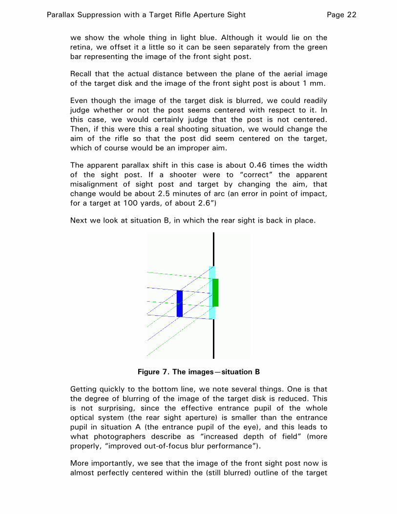
we show the whole thing in light blue. Although it would lie on the retina, we offset it a little so it can be seen separately from the green bar representing the image of the front sight post.
Recall that the actual distance between the plane of the aerial image of the target disk and the image of the front sight post is about 1 mm.
Even though the image of the target disk is blurred, we could readily judge whether or not the post seems centered with respect to it. In this case, we would certainly judge that the post is not centered. Then, if this were this a real shooting situation, we would change the aim of the rifle so that the post did seem centered on the target, which of course would be an improper aim.
The apparent parallax shift in this case is about 0.46 times the width of the sight post. If a shooter were to “correct” the apparent misalignment of sight post and target by changing the aim, that change would be about 2.5 minutes of arc (an error in point of impact, for a target at 100 yards, of about 2.6”)
Next we look at situation B, in which the rear sight is back in place.
Figure 7. The images—situation B
Getting quickly to the bottom line, we note several things. One is that the degree of blurring of the image of the target disk is reduced. This is not surprising, since the effective entrance pupil of the whole optical system (the rear sight aperture) is smaller than the entrance pupil in situation A (the entrance pupil of the eye), and this leads to what photographers describe as “increased depth of field” (more properly, “improved out-of-focus blur performance”).
More importantly, we see that the image of the front sight post now is almost perfectly centered within the (still blurred) outline of the target

Parallax Suppression with a Target Rifle Aperture Sight Page 23
disk. There has been no parallax shift, and the shooter would not have any reason to misaim the rifle.
Why did this happen?
As we described in the body of the article, the “point of perspective” of an optical system (the place from which the system seems to be looking at the world from a standpoint of perspective, parallax, etc.) is the center of the entrance pupil of the system. We see here why. An actual “view” of the front sight post and target from a vantage point off that axis (as we saw in case A) would involve rays traveling to that off-axis location. But the rear sight aperture only admits those rays that would be captured by a “viewer” located on the sight axis. In effect, the “view” is forced to be from the sight axis. Thus the effective point of perspective is on the sight axis.
#