PARAFOIL FIH EFRAC - Defense Technical … ~ APPMUT-71.38 PARAFOIL FIH EFRAC JOHN D. NICOLAIDES AND...
72
CV ~ APPMUT-71.38 PARAFOIL FIH EFRAC JOHN D. NICOLAIDES AND MICHAEL A. TRAGARZ UNIVERSITY OF NOTRE DAME TECHNICAL REPORT AFFDL-TR-71-38 JUNE 1971 App~roval for pubki rde~m; ditrbutias unlimitd. Eepmduced by NATIONAL TECHNICAL INFORMATION SERVICE Spilngflhld Vi. 21151 AMR FORCE FLIGHT DYNAMICS LABDtA~k~Y AMR FORCE SYSTEMS COWMMD WRGTPT'M AMR FORCE BASE, 01IO 1' 1
Transcript of PARAFOIL FIH EFRAC - Defense Technical … ~ APPMUT-71.38 PARAFOIL FIH EFRAC JOHN D. NICOLAIDES AND...

CV ~ APPMUT-71.38
PARAFOIL FIH EFRAC
JOHN D. NICOLAIDES AND MICHAEL A. TRAGARZ
UNIVERSITY OF NOTRE DAME
TECHNICAL REPORT AFFDL-TR-71-38
JUNE 1971
App~roval for pubki rde~m; ditrbutias unlimitd.
Eepmduced by
NATIONAL TECHNICALINFORMATION SERVICE
Spilngflhld Vi. 21151
AMR FORCE FLIGHT DYNAMICS LABDtA~k~YAMR FORCE SYSTEMS COWMMD
WRGTPT'M AMR FORCE BASE, 01IO
1' 1
UNCLASSIFIEDSecurity Classifcstion
DOCUMENT CONTROL DATA - R & D(Security classificationof t.1i , body of abstract and indexing annotIeion must be enteted when the overall report is clsaeified)
I. ORIGINATING ACTIVITY (CoopCiete a1utho) 28. REPORT SECURITY CLASSIFICATION
University of Notre Dame UNCLASSIFIEDNotre Dame, Indiana 46556 .
N/A3. REPORT TITLAr
Parafoil Flight Performance
4. DESCRIPTIVE NOTES (7ype ot report mid Inclusive delw.)
Final Reiort. ADril 1968 to April 1971S. AUTHONRI) (Fitrenmm, middle Initial, last nner)
John D. Nicolaides and Michael A. Tragarz
5. REPORT OATE ?a. TOTAL NO. OF PAGES 7b. NO. OF REFS
June 1971 83 14be. CON',RArT OR GRAN
T NO. be. ORIGINATOR'S REPORT NUMIBERIS)
Contract AF33615-68-C-1459b. PROJECT NO.
6065 N/A4065 01 Ob. OTHER REPORT .0,(5 (Any oi.er.mnlbere "t,.ey be 0..0,0-.dthis report) ,
4065 01 009 AFFDL-TR-71-3810. OISTRIBUTION STATEMENT
Approved for public release; distribution unlimited
11- SUPPLEMENTARY NOTES I1. SPONSORING MILITARY ACTIVITY
Air Force Flight Dynamics LaboratoryN/A (AFFDL/FER)
WPAFB, Ohio 45433IS. ABSTRACT
/The steady state flight performance of the Parafoil is computed by using aerody- .namic cRefficient data obtained from wind tunnel tests 2f both small scale models .
-(SG-4-,.' and full scale aspect ratio 2.0 units 14"--ft9. The actual free flightperformance of the Parafoit is obtained from both manned ascending flights andmanned jumps from aircraft. Attention is also given to the flight stability andcontrol of the Parafoil and to its unique landing flare. The agreement betweenthe performance predictions based on the wind tunnel data and the results obtainedfrom actual flight tests is presented. The performance of a more advanced aspectratio 3.0 Parafoil design is considered./
FI RI
D D NOV.41473 UNCLASSIFIEDSecurity Classiltiction

NOTICES
When Gove.rnment drawings, specifications, or other data are usedfor any purpose other than in connection with a definitely related Govern-ment procurement o1eratlon, the United States Goverment thereby incurs -no responeibility nor any obligations whatsoever; and the fact that theGovernment may have formulated, furnished, or in any way supplied theaald drawings, specifications, Qr other data, is not to be regarded byImplication or otherwise as in any manner licensing the holder or any otherperson or corporation, or conveying any rights of permission to manufacture,use, or sell any patented invention that may in any way be related thereto.
n WHITE SWll
MOl. AVAIL NI/Vt
Copies of this report should not be returned unless return isrequired by security considerations, contractual obligations, or notice ona specific document.
*U.S. Gornmowt PrInting Offices 1971 - 759-077/A49

| IN~I A•TF•T FfSeurity Clamssfication
14. LINK A LINK 9 LINK CKEY WORDS
ROLE WT ROLE WT ROLE WT
Parafoi l
Para-Fol 1
Steerable Parachute
Flexible Wing
Hi-Glide Canopy
Parachute
Gliding Parachute
Maneuverable Parachute
Personnel Parachute
Parachute Free Flight Testing
UNCLASSIFIEDSecurity Classification

PARAFOIL FLIGHT PERFORMANCE
JOHN D. NICOLAIDES AND MICHAEL A. TRAGARZ
Approved for public release; distribution unlimited.

1
FOREWOBD
This report was prepared by the University of Notre Dame, NotreDame, Indiana,under U.S. Air Force Contract AF33615-68-C-1459. Thiscontract was initiated under Project 6065, "Performance and Design ofDeployable Aerodynamic Decelerators", Task 606501, "Terminal DescentDeceleration Concepts". The work was administered under the direction ofthe Recovery and Crew Station Branch of the Air Force Flight DynamicsLaboratory at Wright-Patterson Air Force Base, Ohio. Mr. S. Metres andMr. R. Speelman served as successive project engineers during the dura-tion of the effort.
The authors, of the University of Notre Dame Aerospace andMechanical Engineering Depsrment, were J. D. Nicolaides, Professor andM. A. Tragarz, Graduate Student. Contributing students of the Universityof Notre Dame Aerospace and Mechanical Engineering Department wereBarney Goren, John Dunlop, Patrick Sullivan, Robert Hengstebeck, andMichael Higgins.
The University of Notre Dame wishes to acknowledge the contributionsof Major Gerrell Plummer and the U. S. Army Golden Knights at Ft. Bragg,North Carolina and also the University of Dayton Research Institute, Dayton,Ohio.
The manuscript for this report was released by the authors inApril 1971 for publication as an AFFDL Technical Report.
Publication of this report does not consitute Air Force approval ofthe reports findings or conclusions. It is published only for the exchange andstimulation of ideas.
Chief, Recovery and Crew Station BranchVehicle Equipment DivisionAF Flight Dynamics Laboratory
ii

ABSTRACT
The steady state flight performance of the Parafoil is computed byusing aerodynamic coeffici~nt data obtained from wind tunnel tests of bothsmall scale models (50 in.') and full scale aspect ratio 2. 0 units (147 ft2 ).The actual free flight performance of the Parafoil is obtained from bothmanned ascending flights and manned jumps from aircraft. Attention is alsogiven to the flight stability and control of the Parafoil and to its uniquelanding flare. The agreement between the performance predictions based onthe wind tunnel data and the results obtained from actual flight tests ispresented. The performance of a more advanced aspect ratio 3. 0 Parafoildesign is considered.
iii
CONTENTS
Page
INTRODUJCTION . .. .. .. .. .. .. .. .. .. . .. 1
PARAFOIL PERFORMANCE THEORY ............. . . 2
Equations of Motion . ............. . .. 2
Aerodynamic Coefficient Data ......... .............. 3
Parafoil Performance Predictions ................. 3
PARAFOIL ASCENDING FLIGHTS ........ .............. 4
Ascending Flight Test Procedures ................. 4
Ascending Flight Results ........... ................ 4
Flare Maneuver ........... ............. 5
PARAFOIL JUMP FLIGHTS ................ . 7
PERFORMANCE ESTIMATION .................... 8
Ascending Flights ............... .................. 8
Jump Flights . .. . . . . . . . . . . . . . . . . . . . 8
COMPARISON OF FLIGHT DATA AND PREDICTIONS ..... 9
FLIGHT PERFORMANCE OF ADVANCED PARAFOIL DESIGN. . 10
CONCLUDING REMARKS ........ ................. .... 11
APPENqDIX: COMPJI'ED PARAFOIL PERFORMANCE ..... 40
REFERENCES ................ ...................... 74
iv

LIST OF FIGURES
Figure Title Page
1 NASA Tow Test ...................... ...... 12
2 Notre Dame Ascending Flight ...... ........... 13
3 Notre Dame Jump Test .... ............. ..... 14
4 Flight Dynamic System ......... .............. 15
5 Parafoil Aerodynamic Data, Aspect Ratio = 2 . . . 16
6 Parafofl Flight Velocities Wing Loading = 1 . ... 17
7 Parafoil Flight Velocity ... ............. ...... 18
8 Parafoil Horizontal Velocity o............ ... 19
9 Parafoil Vertical Velocity . . . ... .......... 20
10 Air Force 2000# Cargo Parafoil, A= 864 ..... 21
Ila Boeing Chief Test Pilot, Dale Felix ........ .... 22
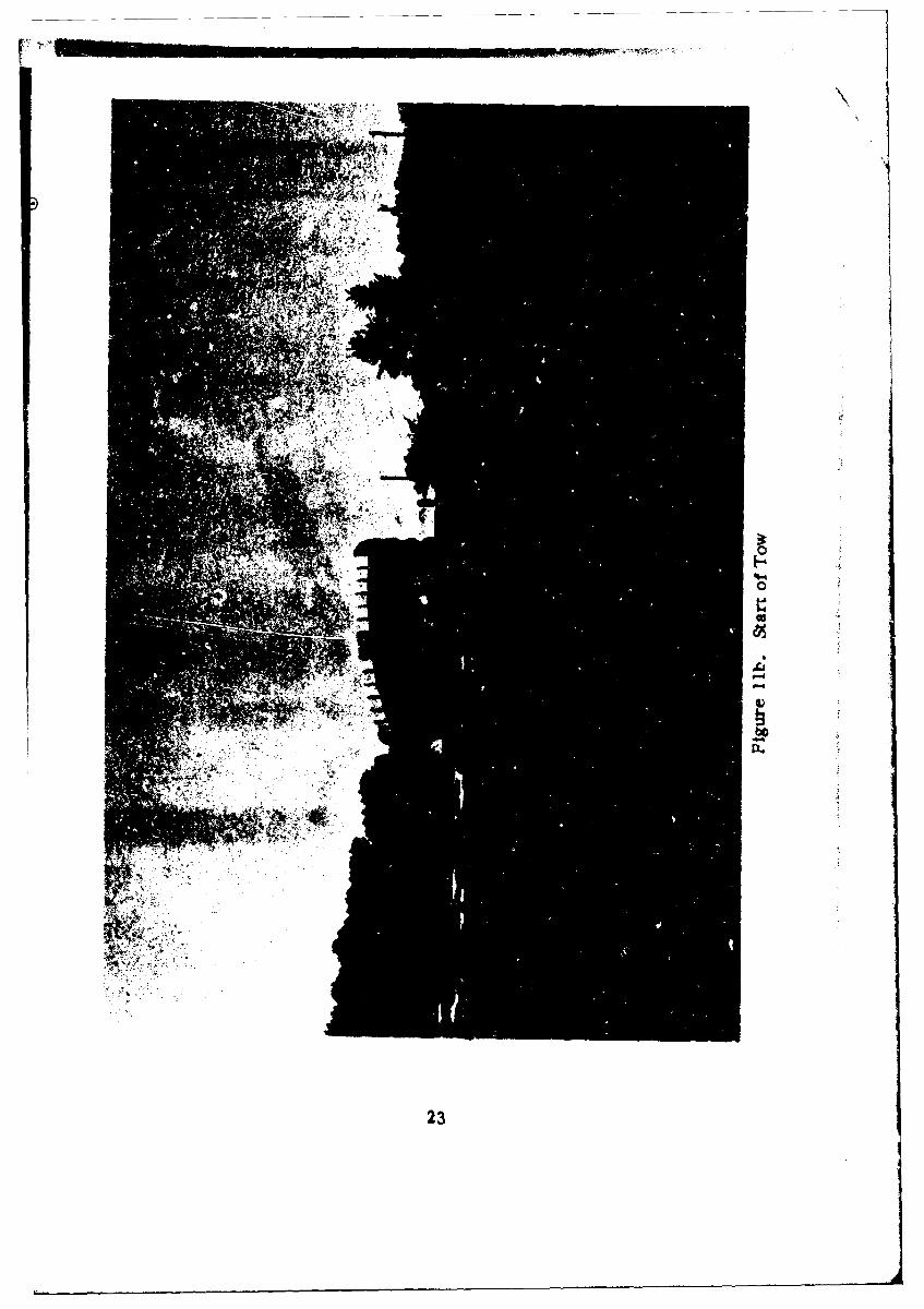
1lb Start of Tow ........ . .......................... 23
1 lc Manned Ascending Flight ......... . . . . 24
12a Flare Landing ...... .................. ..... 25
12b Flare Landing .. . .. . ..... ..... 26
13a Air Force Ascending Flight Data (634) University ofDayton ...... ........ .. ..... ..... ... ... 28
13b Air Force Ascending Flight Data (611) University ofDayton o -...... ...... .... ..... ....... 29
14 Parafoil Maneuvering and Turning Flights 30
ISa Air Force Phototheodolite Data on Flare Maneuver -University of Dayton ......... ............... 31
15b Comparison of Theory and Experiment on Flare
Maneuver .... ..... ..... .................... 32
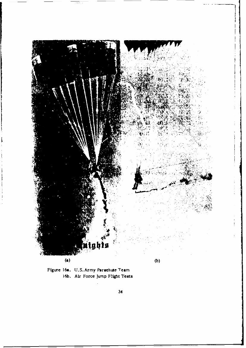
16a U.S.Army Paracbute Team .............. .... 34
16b Air Force Jump Flight Tests ...... ........... 34
17a Comparison of Flight Data and Prediction ..... 36
17b Comparison of Flight Data and Prediction . ... . 37
17c Comparison of Flight Data and Prediction ..... 38
17d Comparison of Flight Data and Prediction ...... 39
V

NOMENCLATURE
A area (feet 2)AR aspect ratio (span /chord)CD drag coefficientCL lift coefficient
D drag forc,. (pounds)Fx force in x direction (pounds)Fz fcrce in z "lrection (pounds)g acceloraclon of gravity (32.2 ft/sec2 )h altitude (ilee)
r.,.nent of inertia about pitch axis (slug-feet 2 )L lift lorce (pounds)
L/T) lift to dreg ratiom mass (07gs)M pitch moment (pound-feet)ND 2.0 (360) Designates Notre Dame Parafoil of aspect ratio 2.0 and
area of 360 sq. ft.R resultant aerodynamic force in z direction (pounds)Rs steady state aerodynamic force (pounds)Range horizontal distance along flight path (feet)t time (seconds)u horizontal velocity (ft/sec)V total velocity (ft/sec)w vertical velocity (rate of sink) (ft/sec)W weight (pounds)W/A wing loading (pounds/ft2)x, yh down range, cross range, and altitude coordinates (feet)x, z Parafoil performance coordinates (feet)a pitch angle of attack (degrees or radians)aT steady state angle of attackv glide angle (degrees or radians)P density of air (slugs/ft3)
vi
INTRODUCTION
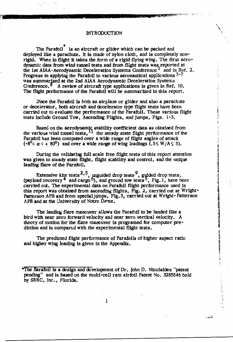
The Parafoil is an aircraft or glider which can be packed anddeployed like a parachute. It is made of nylon cloth, and is completely non-rigid. When in flight it takes the form of a rigid flying wing. The first aero-dynamic data from wind tunnel tests and from flight tests was reported atthe 1st AIAA-Aerodynamic Deceleration Systems Conference and in Ref. 2.Progress in applying the Parafoil to various aeronautical applications 3-7was summarjzed at the 2nd AIAA Aerodynamic Deceleration SystemsConference. A review of aircraft type applications is given in Ref. 10.The flight performance of the Parafoil will be summarized in this report.
Since the Parafoil is both an airplane or glider and also a parachuteor deceL-rator, both aircraft and decelerator type flight tests have beencarried out to evaluate the performance of the Parafoil. These various flight !tests include Ground Tow, Ascending Flights, and Jumps, Figs. 1-3.
Based on the aerodynamjq stability coefficient data as obtained fromthe various wind tunnel tests, the steady state flight performance of theParafoil has been computed over a wide range of flight angles of attack(-80< a < + 801) and over a wide range of wing loadings (.5< W/A•, 5).
During the validating full scale free flight tests of this report attentionwas given to steady state flight, flight stability and control, and the uniquelanding flare of the Parafoil.
Extensive kite tests2,5, nguided drop tests , ggided drop tests,(payload recovery 4 and cargo ), and ground tow tests , Fig. 1, have beencarried out. The experimental data on Parafoil flight performance used inthis report was obtained from ascending flights, Fig. 2, carried out at Wright-Patmerson AFB and from special jumps, Fig. 3, carried out at Wright- PattersonAFB and at the University of Notre Dame.
The landing flare mancuver allows the Parafoil to be landed like abird with near zero forward velocity and near zero vertical velocity. Atheory of motion for the flare maneuver is programed for computer pre-diction and is compared with the experimental flight tests.
The predicted flight performance of Parafoils of higher aspect ratioand higher wing loading is given in the Appendix.
"*The Barafoil is a design and development of Dr. John D. Nicolaides "patentpending" and is based on the multi-cell ram airfoil Patent No. 3285546 heldby SRRC, Inc., Florida.
1i,

PARAPOIL PERFORMANCE THEORY
Eq.,ations of Motion
The equations of motion for Parafoil flight are given by,
EFx = md = LsinV-Dcosy (1)
SFz = m"= -R +mg (2)
EM e (2a)
L CL•V 2 A (Fig.4) (3)
CD _C V 2A (4)D CD 2 A
CL =Ch (f) (5)
CD = CD (a) (6)
R D2 (7)as
The steady state flight velocity is obtained by setting Eq. (2) equal to zero andsubstituting Eqs. (3)-(7) as
v - 71+ 2 o(8)PCl
The rate of sink is given by
w = V sin v (9)
2

The glide angle is given by Eq. (1) as
Y = co"1 (L/D) = tan-1 w (10)
Aero4ynamic Coefficient Data
Extensive wind tunnel tests on various Parafoils have been carriedout.1I Representa ive wind tunnel data for a Parafoil of aspect ratio twois given in Fig. 5. oil, 10, Additional wind tunnel data exists on Parafoilshaving aspect ratios of .5, 1.5, 2.5, and 3. Rigid, semi-rigid, andcompletely non-rigid wind tunnel models have been tested.
Parafoil Performance Predictions
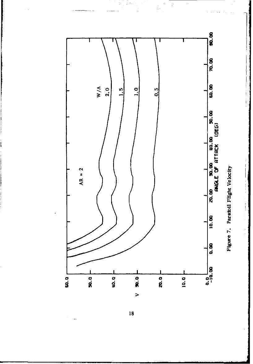
Utilizing the wind tunnel data of Fig. 5 for an aspect ratio 2.0 Parafoiland the basic equations of motion, the steady state flight performance of theParafoil has been computed. For example, in Fig. 6 the total velocity, thehorizontal velocity, and the vertical velocity of the Parafoil are given over arange of angles of attack from -80 to 800 for a wing loading of one. It isnoted that the lowest sink rate occurs near the angle of attar7k for the bestL/D value.
In Figs. 7-9, the various flight velocities are given for wing loadingsranging from .5 to 5 for an aspect ratio 2 Parafoil.
3
3

PARAFOIL ASCENDING FLIGHTS
The Parafoil was first tested as a kite whern it flight stability andaerodynamic efficiency, L/D, could be observed.' However,the variationsin the wind made accurate measurements difficult. When the wind was light,a tow car was used. Fig. 2. When the tow car was stopped, the Parafoil wouldglide stably back to earth. Fig. 10. Ribbons and small parachutes were tied tothe payload in order to provide a measure of the glide angle. Subsequentascending and giide tests utilized smoke for the measurement of lift-to-dragratios. B As on board instrmnentation increased, special flight carts wereconstructed. The flight measurements included total velocity, rate of sink,vertical glide angle and on board movies.
lDuring the early kite tests of large Parafoils (165 ft2Thu en
360 ),it was not unusual for students to be lifted into the air. Thus,whenthe flight test carts were available it became possible to carry out the firstmanned ascending flights. 7,8, 10, 1 The purpose of these ascending flightswas to investigate Parafoil performance and controllability and to study theunique landing flare maneuver. The simplicity and safety of these ascendingcart flights led to the elimination of the cart and to direct manned ascendingflights.
Ascending Flight Test Procedures
The ascending flight testing technique 4is illustrated in Fig. 11. The flierwears a standard jump harness with special tow harness and release. Fig.1Ia. A tow line is tied to the tow vehicle. Fig. 2. When the launch team isready and suitable commands are provided by radio, the tow vehicle movesforward. The two wing men assist in inflating the Parafoil and in providing acoordinated release. Fig. l1b. The flier upon leaving the ground ascendssmoothly to altitude (500 ft to 1000 ft). Fig. 11c. When he is nearly overhead,a signal is given to him to release himself. He then glides stably to earth. 11
At an altitude to approximately 6 ft., he is given a signal to flare out thus re-ducing both his forward velocity and his vertical velocity to near zero. Fig. 12.
Ascending Flight Results
Numerous manned ascending flights have been carried out, the mostextensive of which were those carried out in April and August of 1969 at Wright-Patterson AFB under the directio,. of Air Force Flight Dynamics Laboratory.
4

In these A!.: Force-Notre Dame tests, two phototheodolites were used todetermi•,. three position coordinates, x-down range, y-cross range, andh-altitude. By differentiating this position data, values are obtained for thehorizontal velocity, the total velocity and the sink rate. Representative datareduced by University of Dayton are given in Fig. 13. Values are alsoestimated for the lift to drag ratio; however, it can be seen from Fig. 13bthat the data is quite oscillatory.
Figure 13a illustrates a typical up wind flight (Wind 4 mph). Fig. 13bis a down wind (Wind 7 mph) flight. Here the flier is towed to altitude intothe wind and upon release he makes a right 1800 turn and flies down wind. Atthe end of the flight he makes another 180D turn placing himself into thewind for his flare landing.
One of the primary purposes of the Air Force-Notre Dame tests wasto determine the stability and contrcllability of the Parafoil. Accordingly, oncertain flights, the flier executed various turns of different steepness anddiameter. Plots of selected data from these maneuvering flights is illustratedin Fig. 14. Various control deflections from 1/4 to full were employed. TheParafoil is controlled by deflecting the right or the left trailing edge by pullinga cointrolline. The area of each control surface is 1/2 b x 1/4 -, which is25 ftW for the 200 ft2 Parafoil, ND 2.0 (200). The exact angle of controldeflection is difficult to determine. Full deflection is 900; thus 1/4 deflectionis 250, etc. Following aircraft practice the path of the center of gravity de-fines the turn. In view of the light weight of the Parafoil (121bs), the centerof gravity of the Parafoil plus flier system is taken to be at the flier. As seenin the ground tracks of Fig. 14, when the effects of wind drift are removed,turn circle diameters of 50 It to 400 ft were obtained. This represents goodaircraft performance In view of the fact that the span of the Parafoil ND 2.0(200) is 20 ft. During these maneuvering flights, the Parafoil exhibitedexcellent flight stability.
In order to provide an Indication of the average flight performance, thereduced data was punched on IBM cards. The results obtained from computeraveraging are given in Table I.
Flare Maneuver
One of the most impressive features of the Parafoil is its ability toland like a bird. On landing the flier heads into the wind. His nominal for-ward velocity is 25.6 MPH and his rate of sink is 10.5 ft/sec. , Fig. 3. Whenhe reaches an altitude of approximately 20 ft * he begins to pull down on both
*An experienced flier who commands his own flight normally initiates the flaremaneuver at an altitude approximately 20 ft by slowly pulling down bothcontrol lines so as to program CL and CD in a near optimum manner.
5

control lines. Approximately 3 seconds later his hands are down to hisknees and the entire trailing edge of (bx 4 c) of the Parafoil is fully
deflected (8 E z 900). The Parafoil appears to come to a complete stop in theair and the flier simply steps down lightly on one foot. Figs. 12a and 12b.
One of the purposes of the Air Force/Notre Dame Paraobil FlightTest Program was to measure and to compute this unique flare maneuver.Flight data on Parafoil total velocity and sink rate during the flare maneuveris given in Fig. 15a. In Figure 15b the flare maneuver data in flights 609,605, and 633 have been normalized to steady state flight conditions ofV = 40.5 ft/sec and w = 12.02 ft/sec.*
The equations of motion for transient flight are given by Eq. (1), (2),and (2a). These equations were coded for computer (Univac 1107) integrationusing programed CL and CD aerodynamic data. The agreement between theflight data and the computer integration of the equations of motion are givenin Fig. 15b and are itemized in Table II where it is seen that a substantialreduction in flight velocity and in rate of sink are obtained.*
*'lese conditions are representative of the final phase of the ascending flighttests. The differences from nominal Parafoll steady state flights are due topilot anticipation and minor controlling.
"**These data reproduce the flight performance and agree with the wind tunneldata for flap deflection except for the last four steps which were extrapolated.
6

PARAFOIL JUMP FLIGHTIS
Seven jump flight tests were carried out at the Air Force FlightDynamica Laboratory by the University of Notre Dame in conjunction withthe U. S. Array Golden Knights. Excellent flights were obtained with jumptraining Parafoil ND 2.0 (360), Fig. 16b. However, due to the high winds andthe runway thermals, abnormally high values of L/D were obtained.
Parafoil ND 2.0 (242) jump flight tests have been carried out by theU.S.Armyl3, 7 , (approximately 500+) Fig. 16a. Approximately 180 ParafoilND 2.0 (200) jump flight tests have been carried out by the University. Inthese Notre Dame tests a Magnus rotor was used to measure total flightvelocity; a rate of sink aircraft instrument was used to measure verticalvelocity; altitude and time of flight were recorded in the aircraft; smoke wasused to measure glide angle, and motion pictures of the deployment andflight were taken. From these flights (W/A 1 1. 0) representative values wereobtained for the rate of sink (11 ft/sec) and the total velocity (29 MPH). Onthese jumps the deployment bag and two pilot parachutes are attached to theParafoil so as not to loose them. When this extra drag was cut away, theflight velocity increased (31 MPH) and the rate of sink decreased (10 ft/sec).By measuring the smoke angle, lift to drag ratios in excess of 5 have beenconsistently obtained. For additional lift-to-drag ratio values see Ref. 8 and9.
7

PERFORMANCE ESTIMATION
Ascending Flights
Various Parafoil ascending flights have been carried out, some straight,some turning, and some with intentional pitching disturbance, Table I. * It isnoted that the straight and longer flights better permit the Parafoil to reachsteady state flight performance. Of the quantities measured from these flighttests, the best determined is the rate of sink since it is relatively insensitiveto wind indeterminancy. A review of Table I suggests that a representativerate of sink** for the ND 2.0 (200) is approximately 10.5 ft/sec., for theND 2.0 (360) is approximately 6.5 ft/sec., and for the ND 2.0 (242) isapproximately 8.0 ft/sec. Representative values for horizontal velocity aredifficult to determine because of wind changes and inaccuracy of wind measure -
ment. It is suggested by Table I that the horizontal velocity for ND 2.0 (200)may be 36 ft/sec, for ND 2.0 (360) may be 24 ft/sec, and for ND 2.0 (242)may be 30 ft/sec. A summary is provided in Table I1. Measurements of theflight angle of attack of the Parafoil were found difficult to obtain. Howevermeasurements from the sequence still photographs of the flight angle ofattack of ND 2.0 (200) were found to be approximately 30.
jump Flights
The representative quantities measured in the jump flights were givenpreviously and are also summarized in Table I11. The measurements of totalvelocity are considered quite good. The values for rate of sink are approxi-mate. The values for the lift to drag ratio are considered good since they areobtained from smoke tracks of steady state flight ove-" long observationtimes, Figure 3.
•The data in Table I was obtained by computer averaging all of the AF/DaytonUniversity Parafoil data for each flight. All transient as well as steady statedata is included.
"•For Parafoil ND 2.0 (200) flights 604, 608, and 611 were used since theywere of long duration and therefore allowed the Parafoll to reach steady stateperformance. For Parafoll ND 2.0 (360) flight 630 was used because of itslong duration. For Parafoil ND 2.0 (242) flights 625 and 627 were used be-cause of thtir long duration.
8

COMPARISON OF PREDICTED AND MEASUREDPARAFOIL PERFORMANCE
It is now possible to compare the predictions of Parafotl flight per-formance, Figures 5-9, with the actual measured Parafoll flight performanceas obtained on the Standard Jump Parafofl, ND 2.0 (200), and on the TrainingJump Parafoil, ND 2.0 (360). This comparison may begin by considering themeasured rate of sink for Parafoil ND 2.0 (200) which is 10.5 ft/sec. Enter-ing Fig. 9 or Fig. 17b with this rate of sink and using the curve prepared fora wing loading of one, we find a predicted angle of trim of approximately30. The angle of trim measured from the sequence stills of actual flight wasapproximately 3S. Thus there is good agreement between the measuredvalue and the predicted value of trim as obtained from Figure 17b using themeasured rate of sink.
A comparison between predicted total velocity and measured totalvelocity may be obtained by using Fi we 7 or Figure 17c. By enteringFigure 17c with an angle of trim of 3 we obtain a value of the predictedtotal velocity of approximately 38 ft/sec. The valLw z a velocity "from the ascending and glide tests is 37.6 ft/sec,W(36 + 10.52), and fromthe jump tests is 42.5 ft/sec. The agreement between the predicted totalvelocity and the value obtained from the ascending flights is quite good.However, the measured Jump value is high.
A comparison between the wind tunnel measured lift-to-drag ratioand flight measured lift-to-drag ratio may be obtained by considering Figure5 or Figure 17a where for a trim of 30 we obtain a value of 3.8. The valueof lift-to-drag ratio measured in the ascending and glide flight tests wps3.4 and in the jump tests was 3.7. (See Table 1li. The ascending flight valueis low. However, as mentioned previously, the wind correction is uncertainas is the measured aT.
The agreement with the jump value Js misleading since the jump unitscarried considerable extra drag due to two pilot parachutes and the deploy-ment bag which are all tied to the trailing edge of the Parafoll. As indicatedin Table IIl, the lift-to-drag ratio increases to 4.4 when thits extra drag isremoved. Also, the jump unit is trimnmed at a larger angle of attack whichaccounts for their improved lift-to-drag ratio which agrees quite well withthe wind tunnel value for best trim. Figure 17a.
Figures 17a-17d also contain similar performance comparisons forParafoil ND 2.0 (360). In general the agreement between the predicted andthe measured performance for both Parafolls is good.Thus the Parafollperformance curves given herein should prove useful to designers in con-sidering the application of Parafoils to various missions and requirements.Excellent flare agreement is illustrated in Figure 15b.
9

FLIGHT PERFORMANCE OF ADVANCED PARAFOIL DESIGN
The first multi-cell kites (Falcon and Hawk)" 1 1 had an aspect ratioof approximately 1/2 and 1. The first Parafoil had an aspect ratio of 2.0.Since most Parafoil studies and tests had been carried out on the aspect ratio2.0 units, it was decided to use nominal AR=2 units in the various applicationprograms which arose. The flight tests carried out under this currentprogram also used aspect ratio 2.0 units. (An147, 200, 242, and 360 ft2 .)Wind tunnel tests, however, have been carried out on Parafoil designs havingaspect ratios of .5, 1.0, 1.5, 2.0, 2.5, and 3.0. Thus, since the com-parison of the predicted and the measured flight performance on the aspectratio 2 Parafoil was good, it is of special interest to consider the predictedflight performance of the other units. These calculations of flight performanceof various Parafoil designs are given in the Appendix.
The flight performance of Parafoil ND 3.0 (200) with a wing loading ofone, Fig. 1-24, is of special interest when compared with ParafoilND 2.0 (200).
_ _ L/D V w aT
ND2.0 (200) 4.6 32.6 6.9 80
IND 3.0(200) 6.5 30 4.6 60
Thus, by using a Parafoil of aspect ratio 3.0 the total flight velocity and therate of sink are reduced and the glide distance is improved.
10

CONCLUDING REMARKS
An ascending and gliding Parafoil testing technique has been developedand has been successfully utilized for the determination of steady state flightperformance data. Both straght flights and turning flights have been carriedout from altitudes of approximately 1000 ft. The unique landing flaremaneuver has been measured and analyzed.
A technique for manned jumping the Parafoll from aircraft has beenevolved and has been employed for the determination of Parafoil flight per-formance.
The equations of motion for steady state Parafoll flight have beendeveloped and coded for computer computation utilizing basic Parafoll windtunnel data. The computer runs have provided predictions of Parafoil per-formance for various wing loadings and trim angles.
A comparison of the predicted flight performance of the Parafoll withthe measured flight performance of the Parafolil, as obtained from ascendingflight and glide tests and from jump tests, has been made. The agreementbetween the predicted performance and the measured performance is good, andthus a designer, desiring to use the Parafoil in various applications, maywith confidence employ the curves and data in the report.
The flight performance of various aspect ratio (1-3) Parafotl designs#t difrent wing loadings (1-10) and trim angles (-80 - 670) is given in theAppendix...
i
$
11

S4 ffFigure 1. NASA Tow Test
C.,
12

4\
id
'3L

14

L
x D
'Img
Figure 4. Flight iDnamic System k
gnsi.

xc
C4 d
IC4I
ly 0
a /-:16S

-S
17-
SI
188

• ci
q. 0
19
- 2
n GI S
S~- S
0 i-- 0 'I"
: 4.- - -S
Iii
19 *
[ . . .. . . .

C48
lS
qg
...................... .. .. .. ... .. .. .
C! 9~
zr itS
20-

4
I' I
if!
Figure 10. Air Force 20000 Cargo Parafoil. A- 864.
21
h..

I!
_b
22
22
0\
02
23

Figure I 1c. Manned Ascending Flight
24
L

OT~r
Figure 12a. Flare Landing
25

26

TABLE I
ASCENDING FLIGHT DATA
(Low aT)
FlightFligh Duration_(sec) V(ft/sec) u w LD A (ft2) Type
603 44.7 3s.4 32.7 13.0 2.7 200 St.604 50.7 33.2 31.3 10.6 3.2 200 St.605 51.5 30.7 27.9 12.6 2.4 200 St.606 42.0 32.8 29.1 13.8 2.1 200 St.607 48.5 28.1 24.3 14.0 1.9 200 St.608 57.7 32.0 30.1 10.5 3.2 200 St.611 59.2 36.3 34.3 10.5 4.1 200 DW612 47,2 40.3 37.9 12.6 3.4 200 DW613 37.7 42.9 40.4 13.7 3.0 200 DW614 44.5 41.2 38.8 13.3 3.0 200 DW617 59.0 36.9 34.7 12.3 2.8 200 Turns618 46.2 32.0 28.8 13.1 2.5 200 Turns619 42.0 38.2 34.3 15.9 2.7 200 Turns620 39.2 35.4 31.5 15.5 2.2 200 Turns623 45.2 35.7 32.7 13.7 2.5 200 Pitch624 50.2 33.8 30.8 13.8 2.7 200 Pitch625 94.7 31.3 30.1 8.0 3.9 242 DW 2:626 54.2 32.5 30.1 10.8 3.5 242 DW627 73.0 29.9 28.7 7.9 4.0 242 DW628 79.0 26.7 25.0 8.9 2.9 360 DW629 92.2 25.1 23.8 7.5 3.5 360 DW630 '9.0 23.8 22.8 6.0 4.1 360 DW631 ,,.2 36.7 34.5 12.2 2.9 200 DW/P632 52.7 34.2 31.4 13.2 2.4 200 St/P633 40.0 38.3 35.9 13.1 2.8 200 DW/P634 44.5 35.4 33.1 12.2 2.7 200 St/P636 47.7 37.9 35.3 13.6 2.7 200 DW/P
W 185 # (200 ft2) St. = Straight FlightW = 197# (360 ft2 ) DW = Down Wind FlightW = 186# (242 ft2 ) Turns = Turning Flight
Pitch, P = Pitch Disturbance
27

600 600
400 h 400ymh
200 200
S0 0 1 t I I I a
0 200 400 600 800 1000 1200 0 400 800 1200 1600 2000x Range
600
400
h200
0
40 , _
V 30.20100
o Lod• p
6-
4,.
L/D
0 10 20 30 40 50 60t (sec)
Figure 13a. Air Force Ascending Flight Data (634) University of Dayton
28

600
h400,400
V 200 id 7mhh20
22000 20 400 600 00 10 400 800 1200 1600 2000
x Range
400
h200
40 O30
V 201001
20
W 0
10
8
6L/D
4
2
00 10 20 30 40 50 60
t (sec);
Figure 13b. Air Force Ascending Flight Data (611) University of Dayton29

1000
800
600
-y 400
20
0 I | 2 I| I A
0 200 400 600 800 1000 1200 1400 1600
x
#618 \ #619 "N60d#620400. 400 200win 7- mh,40 wind
3ypyy\4 3 mph
200- 260 4 6, 0 00 2b ,- 6) 2000 1 , 0 -- L I OI
00 200 400 600 0 200 400 600 0 200 400 600
x x
Figure 14. Parafoil Maneuvering and Turning Flights
30

50 - 50
40 - #605 40 #605
30 30V 20 w 20
10 - 10
0 0I v0 5 10 15 20 0 5 10 15 20
t t
50 #633 50 #633
40 40
30 30 "
V 20 w 20
10 , 10
0 I I I 0 I I I0 5 10 15 20 0 5 10 15 20
t t
Figure 15a. Air Force Phototheodolte Data on Flare Maneuver -
University of Dayton
31

40
V35
30
25
Flight 604Flight 605Flight 6332Oiriputer Integration20
15
10
w
0 I5 Flight 604 •' i•-J /
~Flight 605
Flight 6330 • ~~Computer Integration-----I
-1 0 1 2 3 4t
Figure 15b. Comparison of Theory and Experiment on Flare Maneuver.
32

TABLE 1I
LANDING FLARE MANEUVER COMPUTATION
Time UVel WVel TotalV X Ft ZFt CL CD
. 38.75 12.02 40.57 .00 .00 .477 .151.25 38.68 11.67 40.40 9.68 2.96 .477 .151.50 38.55 11.40 40.20 19.33 5.84 .477 .151.75 38.33 10.16 39.65 28.95 8.53 .544 .166
1.00 37.90 9.20 39.00 38.48 10L 94 .544 .1661.25 36.65 7.72 37.46 47.80 13.04 .603 .2211.50 35.31 7.00 36.00 56.80 14.87 .603 .2211.75 33.72 5.52 34.17 65.43 16,41 .723 .2582.00 32.11 5.00 32.49 73.66 17.71 .723 .2582.25 29.47 3.77 29.71 81.35 1&.77 .893 .3932.50 27.21 4.00 27.50 88.43 19.71 .893 .3932.75 23.04 3.86 23.36 94.68 20Q 64 1.143 .8123.00 20.27 5.50 21.00 100.06 21.79 1.143 .8123.25 17.69 6.33 18.79 104.78 23.24 1.537 1.1473.50 16.12 8.00 18.00 108.99 25.02 1.537 1.147
X = Horizontal Distance
Z s Vertical Distance
33
"I -
(a) (b)
Figure 16a. U.S.Army Parachute Team16b. Air Force j•up F!ight Tests
34

TABLE III
SUMMARY PARAFOIL FLIGHT PERFORMANCE
Ascending Flight Data
Parafoil w u V Vmph L/D W/A
ND 2.0 (200) 10.5 36 37.6 25.6 3.4 .925
ND 2.0 (242) 8.0 30 31.0 21.2 3.7 .77
ND 2.0 (360) 6.5 24 24.8 17.0 3.7 .55
Jump Flight Data
ND 2.0 (200)
(2 chutes and bag) 11 41.0 42.5 29 3.7 1.0
( clean ) 10 44.4 45.5 31 4.4 1.0
ND 2.0 (360)8 8.4 -- -- -- 4.5* .59
ND 2.0 (242)8 --. . 25+13 5.5* 1.0
Smoke measurements.
35

co
n Cd
00
0
00
III
0 r0
0'
NN
-ý
I-. 0iZ- ~
:16

0
0U
0o a
0
0n-u-I
..................
0 '6~ C; 8W ingM
Cl -~37

S~8
dS
dd44a
II
S
10
(J3S/1.4l 11013A33 -MIY,
38

II,
a'a

APPENDIX I
COMPUTED PARAFOIL PERFORMANCE
Robert Hengstebeck*
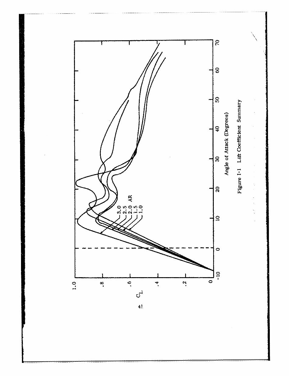
The steady state flight performance of the Parafoil with various winA,loadings (0 < W/A < 10) and at various flight trim angles (-80 < aT + 670)may be computed from the wind tunnel data which is now availab1e on Parafoilsof aspect ratios 1.0, 1.5, 2.0, 2.5, and 3.0. A summary of the wind tunnellift coefficient data is provided in Figure I-1 for Parafoils of various aspectratios. 8, 1l It should be noted that the Parafoil does not exhibit the stallrange of angle of attack from -80 to over 750. The important lift to drag ratioplotted as a function of trim angles of attack is given in Figure 1-3.8 Thecorresponding wind tunnel drag coefficient data is illustrated in Figure 1-2.
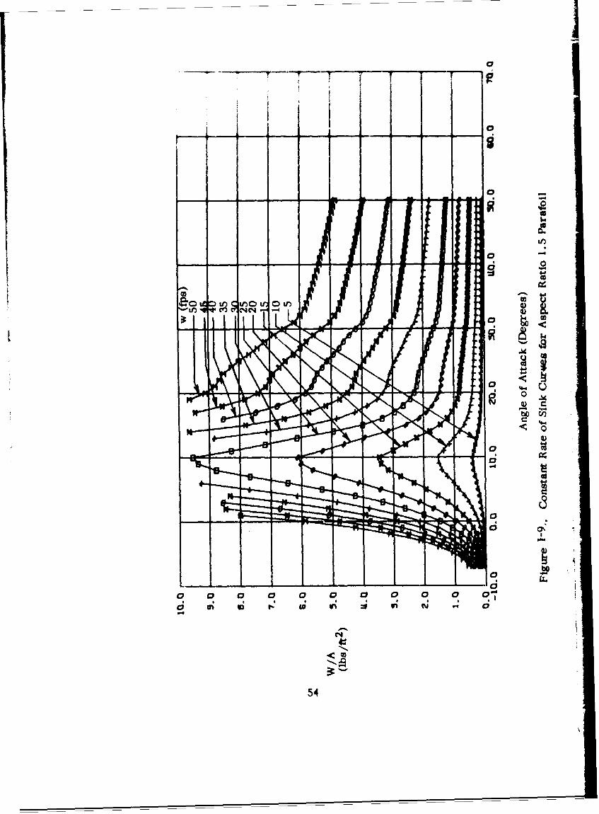
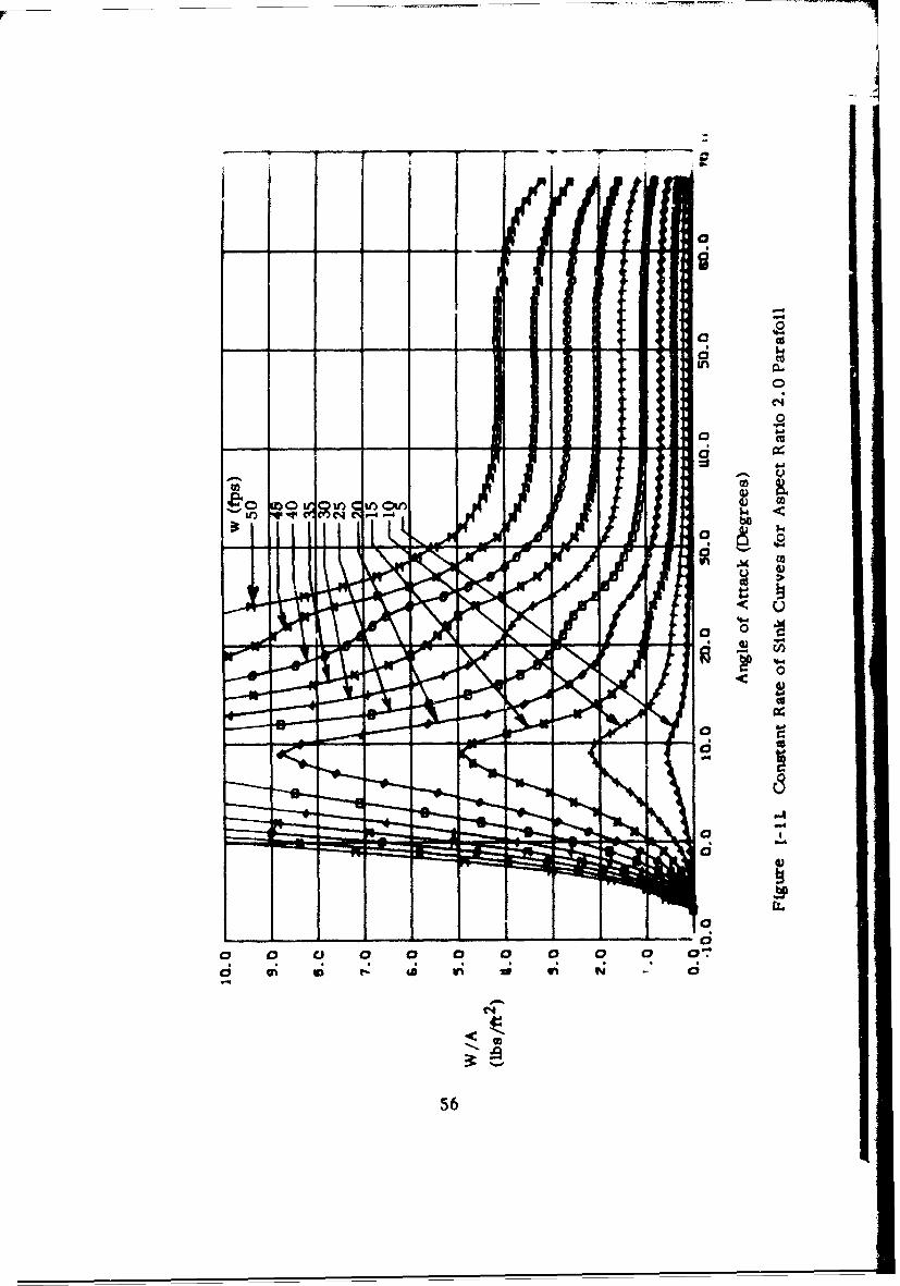
Utilizing the equations of steady state motion given in the basic report,the flight performance of the various aspect ratio Parafoils is computed.Table I-1 lists the aerodynamic data used in the calculation of the performanceof all the aspect ratios. The results of these computations are shown inFigure 1-4 and Figure 1-5 for a wing loading of 1.0. In Figure 1-4 the rate ofsink is plotted as a function of angle of attack for each aspect ratio, and inFigure 1-5 the total velocity is plotted for each aspect ratio. In order to easilyfind the maxirtmu wing loading allowable for a given rate of sink Figures 1-6through 1-15 were generated. Each curve represents a constant rate of sink,and rates of sink from 2 feet per second to 50 feet per second are representedfor each aspect ratio.
*Resear'ch Assistant.**At the time of these computations, wind tunnel data beyond 670 was not
available.***The model used in the Notre Dame wind tunnel tests had various proturbences
(e.g. bolts, nuts, and thick metal flares) which were required in the con-struction and mounting of this semi-fabric model. The additional estimateddrag coefficient due to these proturbences is CD z. 023. The standard flightParafoil ND 2.0 (200) has line and payload drag estimated to be CD =. 026.Since these estimated additional drag coefficients are approximately thesame, the wind tunnel data may be considered to represent a complete flightParafoil with lines and payload. The line drag estimate is based on anarea of 5.5 ft and a drag coefficient of .6 (Fig. 18, Hoerner). l4. The pay-load drag estimate is based on an area of 2.5 ft2 and a drag coefficient of.8.
40
/N
/~o
00 1-
000
o41.J0
41.

* .. ... ',,
I i_ _ __ _ __ __ _ __ _ -.--- ---
>1
* b.0
I'0.
, Aia
SiK
*. . ..... ....... .
SC
42. . .0
F.. *
P-
V or
4t2

. - . .u 0
00N C0)
tfl
* .4
43~

o v W r4 W"W -cýot -
N I 0N vt 0 00t-co 9- P-4 -4 \ if,4v n00
-- 1- 4NNene)*vvtot fV f COt~'~ M~ N C4 CNN
0o Cf f -t)t 00 N0 4OA(,mXt 00OyN g\ g to
N- 'O\alC) \ 00 Cf '0% 0 to4 NoCC)-0C -0 ON '4 0 00-4 LONo(V4 a. * * .- _: .4 .4 *4 .f *fC .4 M: M. * 4 1; 4 4C 4
to4- 00 00, a ~C ~C ~ CU4 § C12 00 N~ "I~N
N l_0 - 1%t-ato-4\0-- 0 0 N N ky
N v 4'- O\ P-4 v44' \0G Nvt-a N N0 t- NNrc* C * C4C C4 C4 C4 Cf Cý C cf C4 Cf C4 C C4 C4 C4 C4 C
-f 9W- f 0C)a CV) 7-4 Na,- 000Cf) rN U T CY t-0 '1 0 ot f
-4 -1- 4ý 4MC N N N N N
ce N N N N N N N C,- *f W *. \* 00 a. o N v *f r, a, 4
< ~ ~ ~ ý - CO -00\0~q - ~ C 0 N
09 00-NN0io \O'-4 co 4r 0C 4. 0i)- o-
/3F4NN NC~ NI-0 Cf C C Cf Ce Ce co c? 9e m m v v to C ý 0C G\ C N C f p *
NNN Nco00t4Y4N WNU~I0 C NoC C C " C N c c! c! c! c! C 0! c! "I c! c! CCC
-4N O ' ~ f N O%
<4 '-- Rf N~0 "D N0 i4 -N i -44 to -Wa V-*4 C4 C m \0 \C C- C0 0 m C C\ 0\ m ON C0 C0 0C 0
<4 V-4N N " vt t 0 l -W 00 0 -t -t -\
r_ *~ C4 \0 \ Cf C_ Cf C, 40 .0 N \C C * N q C ý CD ce C0 PC C C
N r-Nr ýNr r -NII f-4 -4 N N I) S Y V V )Ir D0 0 r.
r" f~ý G v--4 m 44 m 0\ 'jto0

*V *71- V %D 1- 0. . W 0 N a M M 0 M M .- 0% \
'D 0 tf cf)op00 % V 4c 0"00 - y -Cr( ~ m -4 00r-4 01 0
m )N -40 0--4C o o00- ~N10\ CO a,8 N00 % n "0
C4 00% 0 P- so0 vIV)N N qg 8 % 0000 00 t" 0N l% " N
t- N 0 -1 al a *4 a a a a a a\ a a 0 0 a a a * a
o0 '0 10 . . 0 00 0 0 6i- 0 0 * . *
Nl N. W4 W 4 eq "A4 "-I4 "-I V-4 -4 r-4 "- -4 P- 4 W.4
En r,00 v 00 ar%~ 00r.4N 0 0 N n N o ,
L V. co A Pý4 % O 044 O
r, to C()-V 0% 4ý 00I % 0-e 0 QC00% V-4 N a% o %.0 -4 - P-
CL4 % W - %00 0 M NN r- P-4 r 0 r 0% 00 0000 r r t
,~~C1N v r 001OOD04 ON w~'o4~~q m 0C~ C-- 4w4C 0 fl- c'if'0O -4N)rl ýP4 f 0 0P4 U? - V-4CC) U.0) C%0Go
< C4
4t,. Cf) II U t*-.- 0000rý(.. v 0 0 -
04 oo29 00 t o 0 % Mtt r 0 Q
N )r 0 0%Q " V -0%00 V- mv- t % 0 - NA UlU 'D 1,sf
v v0'40 v '.o o0V N 1R00 -t t 00 0 0
C .u0 f' 0 o' 'Cf) v0c 0 % %Nu N 0 0 --4CK N V N0C
S r- 47 0 CY 0 % IN 0 .O.0ý V- 0lQ. %0CY) v %0 r- N crCýCoV Vv t i 0NOsorl r t"W'.a4 - t '-4 - r0 0 0 00
N- NN NoN 0000 ANNNNN Go 8 CY) 0
NNNN R -- f) C4,14C9 -04 10 P414
V a a1 a* a a a a, a 0 a ao a N - 1- a% aa
r- tOf4 W) V) W) 0 0 V)0V) 0 V) w V
C) 0 0, 0 - 12,a,,00 a. Nco y ý4C4V C4 C0 m cf r, t,
04 ýs r'- r'- t0 ,, " 2 1)"0 r"oV)4oV5:
0 L nt ot ot nt ,i

U- .I V V r.S W . -- Lt . o r- * . 0 P- 444 4 to -44.4
""S0 - ~ c 4 SI P-4 V-l 4
0 -0 q 4 C4 4 to *4 N M 00 V4 0 %0 Go V4 ý C4 V4 .- 0 4
C4 a4 04 4ý ** m * v m 49 V. 4 * 4 4 r-4 4 . 0 N
0 r- "400 00 C*4 000 in vCf4 '-4 P- Q% 0% 0 l
C4 to %0 r4 V4 m * v 4 4 D In to w w
r, 00 0000 00000 o 0% m a% a.-01 O% a% 0N %Olt llok m
Im in NO - M 4 C4 C4 *f X * 4 in 0, 0 0 4l 4n * to to
C4r-r-t-r"t-t-W o o 0 G o00 00co00go00 0
U c to-rr-' 00vc000000) SC4f 0 C)vr-r i8 * %4 t* *0 "4 C4 *o 4" *l w w 47 04 a, 04 m 4N 4 4
P-4~ r- r rlr- - t-anco000 00 0000co00 000MGo00 o Go000000o
n .0 - 0. 04 V4 -4 C4 4CAAA 0mmmCf nmf)mn
00- 00 CD go(20 m011 71 m01 m m m (% m0%%ok maka,0 , 0%0 a',0m
C4) 0OO0v 4mCf) aUl r-. v r 00) C 00 O0r- g
<CI~~~v N-4~4~ ~
Ln c 00 r- ')4 - r No V) WI) '000 N -C'
W- -4 09 00 N '-4 . 0%0N-I)4 r-rN mww r, -m ,Nmm N N N N N " V-44 -4 -4 - %0 0 v N p 4v 4 I
U 4 n t '0 f cc iVc nn4 t' tI lý'
LrO q, O% U CV. 0'c@ IIZI'%DO
C'- -4 )00 r- 40 cO' r-4cc)'4 r-. 0 m ~ ml f-%0v
46

00
C4C
Scca
U
II
o o <,g
o 0 0
4 ° 00
0
0 0
0
0 04
~v
17,

Cd1
L -
Cl9
0
°0 b
48

0
cft) u•d
0 00CCI
°.0
0 I l 4
0
CrC
49

I. I.
Cl-9
b0
CD
I|
C4~
4.'
~.6
oD
) -4
0
50

.0
0)
0)
C144

Vý _rV
4wlw
C'9-
520

0
0
0 FID
00
C4.
go
=p Ci)
C44
v// A en" '
La
'1 0
"II
S!S
be
I t
0 So a-0
54-

00
I +- - - --• - - ; g
% I
, 7 0
0 0
a.
€",,I<a)
s.Co -O
0.
.2 w ::f y 0.
55
0C,'
-40
o
0
a-
C4Z
o56W r
56

FC
0 ca
ID 014o
~O oOO CR0'0~57

i e
--- -..- - - -'S
to-j
doc 0
"" •
0
Cu
oo
C~Cu
o58.•m6
58C

C0
bO G
C3)
V4
e~4
59

dd
o o.0
10.
0 Op.
Oax cd
-4-
4-a
bý W; 96
6C - O

REFERENCES
1. Nicolaides, John D., and Knapp, Charles F., "A Preliminary Study'of theAerodynamic and Flight Performance of the Parafoil," AIAA 1st Conferenceon Aerodynamic Deceleration, University of Minnesota, July 8, 1965.
2. Nicolaides, John D., "On the Discovery and Research of the Partfoil,"International Congress on Air Technology, Little Rock, Arkansas,November 1965.
3. Ntcolaides, J.D., Knapp, C. F., "Para-Foil Design", University of NotreDame Report (866). Prepared for the Ur. S. Air Force Flight DynamicsLaboratory, Wright-Patterson AFB, Ohio under Contract AF 33(615)-5004.
4. Knapp, C. F., and Barton, W.R., "Controlled Recovery of Payloads atLarge Glide Distances, Using the Parafoll". Presented at the AIAASounding Rocket Vehicle Technology Specialist Conference, Williamsburg,Va., Feb. 1967; J. Aircraft, Vol. 5, No. 2; Sandia LaboratorySC-R-67-1049, under contract No. 48-2942, November 1967.
5. Nicolaides, J.D., "Summary Report on Parafoil Targetry", Universityof Notre Dame Report, 1968, prepared for the U.S. Air Force, EglinAir Force Base, under Contract No. AF08(635)-6003.
6. Metres, Solomon R., et al. "Project Pin Point" Review Report, Air ForceFlight Dynamics Laboratory, Director of Laboratories Air Force SystemsCommand, Wright Patterson Air Force Base, Ohio!
7. Saar, J., LIFE, Sept. 1968.
8. Nicolaides, J.D., Speelman, R.J., Menard, G.L.C., "A Review ofPara-Foil Programs", AIAA 2nd Aerodynamic Deceleration SystemsConference, El Centro, Calif., Sept. 1968.
9. Menard, George, "Performance Evaluation Tests, Parafoil ManeuverablePersonnel Gliding Parachute Assembly Aspect Ratio 2 ,Area 360 sq. ft. ",September 1969, Rpt. 2-69.
10. Nicolaides, J. D., "Improved Aeronautical Efficiency Through PackableWeightless Wings," CASI/AIAA Meeting on the Prospects for Improve-ment in Efficiency of Flight, Toronto, Canada, AIAA Paper No. 70-880,July 9-10,1970.
11. Nicolaides, J.D., "Summary of Para-Foil Wind Tunnel Tests", Universityof Notre Dame report, 1969, prepared for the U.S. Flight DynamicsLaboratory, Wright Patterson AFB, Ohio under contract F33615-67-C-1670.
61

REFERENCES (continued)
12. Neumark, Walter, "Ascending Flight Technique", Manchester, England,1970.
13. U. S. Army, Golden Knights Brochure, 1970.
14. Hoerner, Sighard F. , "Fluid-Dynamic Drad: Published by the author,Midland Park, N.J. 1965.
*Reference 6 has been superseded by:
Speelman, R. J., et al. Para-Foil Steerable Parachute, ExploratoryDevelopment for Airrop System Application. Air Force Flight DynamicsLaboratory Report, AFFDL-TR-71-37.
AIR FORM. O•O71/l2O
62