
paper551_551
10
Introducing SOFT MAC Ghassan M. Abdalla*, Mosa Ali Abu-Rgheff** and Sidi-Mohammed Senouci*** *University of Khartoum, Sudan **University of Plymouth, UK ***University of Bourgogne, France [email protected] ABSTRACT The IEEE is working on a MAC standard (802.11p) for VANET based on 802.11e. Although the access function of 802.11e supports QoS by using different counters for different QoS requirements, it reduces to a best effort service and low performance when the number of nodes increases. Some applications of VANET, particularly safety related, have strict QoS requirements that cannot be guaranteed by 802.11p especially in heavy traffic conditions. To resolve these issues, we propose a Space-Orthogonal Frequency-Time medium access control (SOFT MAC) protocol that can support QoS requirements and is compatible with 802.11 standard. The proposed MAC allocates guaranteed transmission slots via reservation and also has a random access period for best effort service. Reservations are allocated in a distributed manner without the need for a basestation or a cluster head. In this paper we analyse and discuss in details the rules and algorithms that govern SOFT MAC protocol. The analysis of SOFT MAC proves it achieves higher saturation throughput than 802.11. The improvement in throughput depends on the maximum number of reservation slots in SOFT MAC. Keywords: 802.11, DCF, CSMA, FDMA, MAC, OFDMA, PCF, SDMA, TDMA. 1 INTRODUCTION Vehicular Networks (VANET) aim at reducing the number of accidents in the road by exchanging safety and road condition information and, at the same time, providing commercial applications. The IEEE is working on a Medium Access Control (MAC) standard known as IEEE 802.11p. The standard is based on the previous 802.11e which uses an Enhanced Distributed Co-ordination Function (EDCF), an extension of the Distributed Co- ordination Function (DCF), to organise channel access. Since DCF is a random access mechanism based on Carrier Sense Multiple Access with Collision Avoidance (CSMA/CA), it has an unreliable broadcasting service, achieves low throughput when the number of devices increases and has little support for Quality of Service (QoS) [1-4]. A request-to-send clear-to-send (RTS/CTS) handshake, supported in DCF, can be used to improve the performance of point-to-point transfers but is not applicable to broadcast messages. Since a large number of applications in VANET is broadcasting by nature (e.g. safety messages, location messages, traffic condition messages … etc), the RTS/CTS handshake cannot be used with these applications. Moreover the number of nodes varies with time and location, and peaks in congested areas leading to severe degradation in DCF performance [1-4]. EDCF provides some QoS by using different queues and counters for each QoS requirement, but still packets contend for the channel and may collide with packets having the same QoS requirements (e.g. safety messages from different cars). We propose a MAC protocol which is a combination of Space, Orthogonal Frequency and Time Division Multiple Access (SDMA, OFDMA and TDMA) called SOFT MAC protocol. In SOFT MAC the space (road) is divided into cells and a portion of the available subcarriers is assigned to each cell. These subcarriers are then shared between nodes within the cell via a TDMA protocol. The rest of the paper is organised as follows: some related work is reviewed in the next section. Section III describes the new protocol. Section IV explains the implementation of the protocol using 802.11 standard. In section V the saturation throughput is theoretically analysed and closed form expressions are obtained. The results of the analysis are presented and discussed in section VI then the paper is concluded. 2 RELATED WORK Several MAC protocols for VANET considering different approaches were proposed [5-11]. In [7, 8, 10] a TDMA access mechanism was used, SDMA in [5, 6, 9] and a combination of FDMA and CDMA in [11]. In [8] cluster based MAC (CBMAC) was introduced where unsupervised nodes form clusters and a cluster head is elected to organise access to the channel. Issues of cluster head election, clusters merging and loss of connection to cluster head are usually of concern in this and all cluster-based protocols in addition to the large signalling overhead. UbiCC Journal, Volume 6: Issue 2 833 Ubiquitous Computing and Communication Journal (ISSN 1992-8424)
-
Upload
usman-tariq -
Category
Documents
-
view
213 -
download
0
description
http://www.ubicc.org/files/pdf/paper551_551.pdf
Transcript of paper551_551

Introducing SOFT MAC
Ghassan M. Abdalla*, Mosa Ali Abu-Rgheff** and Sidi-Mohammed Senouci***
*University of Khartoum, Sudan **University of Plymouth, UK ***University of Bourgogne, France
ABSTRACTThe IEEE is working on a MAC standard (802.11p) for VANET based on 802.11e. Although the access function of 802.11e supports QoS by using different counters for different QoS requirements, it reduces to a best effort service and low performance when the number of nodes increases. Some applications of VANET, particularly safety related, have strict QoS requirements that cannot be guaranteed by 802.11p especially in heavy traffic conditions. To resolve these issues, we propose a Space-Orthogonal Frequency-Time medium access control (SOFT MAC) protocol that can support QoS requirements and is compatible with 802.11 standard. The proposed MAC allocates guaranteed transmission slots via reservation and also has a random access period for best effort service. Reservations are allocated in a distributed manner without the need for a basestation or a cluster head. In this paper we analyse and discuss in details the rules and algorithms that govern SOFT MAC protocol. The analysis of SOFT MAC proves it achieves higher saturation throughput than 802.11. The improvement in throughput depends on the maximum number of reservation slots in SOFT MAC.
Keywords: 802.11, DCF, CSMA, FDMA, MAC, OFDMA, PCF, SDMA, TDMA.
1 INTRODUCTION
Vehicular Networks (VANET) aim at reducing the number of accidents in the road by exchanging safety and road condition information and, at the same time, providing commercial applications. The IEEE is working on a Medium Access Control (MAC) standard known as IEEE 802.11p. The standard is based on the previous 802.11e which uses an Enhanced Distributed Co-ordination Function (EDCF), an extension of the Distributed Co-ordination Function (DCF), to organise channel access. Since DCF is a random access mechanism based on Carrier Sense Multiple Access with Collision Avoidance (CSMA/CA), it has an unreliable broadcasting service, achieves low throughput whenthe number of devices increases and has little support for Quality of Service (QoS) [1-4]. A request-to-send clear-to-send (RTS/CTS) handshake, supported in DCF, can be used to improve the performance of point-to-point transfers but is not applicable to broadcast messages. Since a large number of applications in VANET is broadcasting by nature (e.g. safety messages, location messages, traffic condition messages … etc), the RTS/CTS handshake cannot be used with these applications. Moreover the number of nodes varies with time and location, and peaks in congested areas leading to severe degradation in DCFperformance [1-4]. EDCF provides some QoS by using different queues and counters for each QoS requirement, but still packets contend for the channel and may collide with packets having the same QoS
requirements (e.g. safety messages from different cars). We propose a MAC protocol which is a combination of Space, Orthogonal Frequency and Time Division Multiple Access (SDMA, OFDMA and TDMA) called SOFT MAC protocol. In SOFT MAC the space (road) is divided into cells and a portion of the available subcarriers is assigned to each cell. These subcarriers are then shared between nodes within the cell via a TDMA protocol.
The rest of the paper is organised as follows: some related work is reviewed in the next section. Section III describes the new protocol. Section IV explains the implementation of the protocol using 802.11 standard. In section V the saturation throughput is theoretically analysed and closed form expressions are obtained. The results of the analysis are presented and discussed in section VI then the paper is concluded.
2 RELATED WORK
Several MAC protocols for VANET considering different approaches were proposed [5-11]. In [7, 8, 10] a TDMA access mechanism was used, SDMA in[5, 6, 9] and a combination of FDMA and CDMA in [11]. In [8] cluster based MAC (CBMAC) was introduced where unsupervised nodes form clusters and a cluster head is elected to organise access to the channel. Issues of cluster head election, clustersmerging and loss of connection to cluster head are usually of concern in this and all cluster-based protocols in addition to the large signalling overhead.
UbiCC Journal, Volume 6: Issue 2 833
Ubiquitous Computing and Communication Journal (ISSN 1992-8424)

In an attempt to avoid the cluster head issues,ADHOC MAC was developed for VANET [7, 12]. Nodes using ADHOC MAC exchange information about the status of each slot (BUSY/IDLE) as each node senses it. With this information, the nodes are aware of which slots are free and attempt to reserve only free slots. The main drawbacks of ADHOC MAC are the large overhead and fixed number of slots. The state of each slot in the frame must be transmitted along with the ID of the node transmitting in the slot. Under high traffic this overhead is justifiable but under low traffic the protocol becomes inefficient. Moreover since the number of slots is fixed, the number of nodes that can access the channel is limited to the number of slots.
The SDMA scheme was addressed in [5, 6, 9]. The basic principal is to divide the area into small cells, each cell is big enough to occupy only one node and assign a time slot, frequency band or code for each of these cells. The scheme is very reliable and simple but it has poor efficiency since most of the time a large percentage of these cells will not be occupied by nodes and therefore the slots are wasted. Another limitation in these SDMA schemes is that location errors may cause collisions.
The authors in [11] proposed the use of two transceivers. Nodes form clusters and exchange safety and non-safety messages. A cluster head (CH) organises the access to the channels and relays safety messages between clusters. One of the transceivers in the CH is tuned to the safety and control within the cluster and is used to exchange safety and data channel reservation requests from cluster members and organise channel access using TDMA while the other transceiver is used to communicate with other clusters and exchange safety messages using 802.11 MAC. For cluster members one of the transceivers is used to communicate with the CH while the other is used to transmit non-safety data in the channels assigned by the CH. To reduce interference between clusters each cluster uses a different CDMA code. This system has a high cost due to the use of two transceivers. Moreover CDMA has the near-far problem and power control is hard to implement in ad hoc networks since different destinations experience different path losses.
DCF and EDCF use CSMA for channel access. Under heavy load the performance of TDMA is superior to CSMA, however under light traffic CSMA shows better performance. An attempt to combine the two protocols was introduced in [13]. The nodes use CSMA as long as the traffic is below a certain threshold. Once the traffic exceeds the threshold, nodes switch to TDMA and do not switch back to CSMA unless the traffic drops below the threshold. However different nodes will have different traffic conditions, therefore some will prefer TDMA while for the others CSMA will be the best choice. The
Point Coordination Function (PCF) of 802.11 uses a combination of TDMA and CSMA. The basestation announces a contention free period (CFP) in which it polls node for data (TDMA). After the polling finishes or the maximum CP period has elapsed, the basestation announces the end of CFP and a contention period (CP) starts in which nodes use DCF[14-16].
The DSRC standard specifies seven communication channels. Channel 178 has been declared as a safety and control channel while the rest of the channels were left unspecified. The draft of the Wireless Access in Vehicular Environment (WAVE) IEEE standard solves the multi-channel access by dividing time into frames of 100ms interval. All nodes must switch to the control channel for 50ms every frame and may switch to any of the other channels for the other 50ms [17]. The MAC protocol we introduce in the next section is to share a single channel between available nodes. When integrated with WAVE, each channel will be independent from the others and has its own frame, subcarriers, and reservations. As nodes switch between channels every 50ms, they keep records of the status of the control channel and the channel(s) they switch to.
3 SOFT MAC
Our MAC uses a combination of SDMA, OFDMA and TDMA. Instead of defining the cells in SDMA to occupy only one node as in [5, 6, 9], a cell in our proposal usually contains several nodes. Cells can be as big as 1 km in diameter depending on the node density, thus location errors are not an issue. Each cell is assigned a number of subcarriers and nodes within the cell share these subcarriers in time. Time is divided into frames and each frame is divided into slots. However unlike Reservation ALOHA (R-ALOHA) [10, 18] and ADHOC MAC there are two types of slots or periods, reserved transmission slots (TS slots) and reservation (RS) slots/period. TS slots cannot be accessed without prior reservation while the RS period is accessed via a random access scheme(e.g. DCF or slotted ALOHA). The number of TSslots varies with the number of reservations as will be explained and the RS slots occupy the rest of the frame. Under low traffic most of the frame will be RS period while at high traffic most of the nodes will have a large amount of data and reserve TS slotstherefore most of the frame will be TS slots and hencethe performance will approximate that of TDMA systems. Hence the protocol should provide the performance of random access methods under low traffic and the performance of TDMA under heavy traffic.
3.1 SDMA-OFDMA in SOFT MAC
We assume the system uses N subcarriers, each node knows its location and the network is time and
UbiCC Journal, Volume 6: Issue 2 834

frequency synchronised possibly via GPS. In the SDMA scheme the roads are divided into cells of radius R and a portion Nc of the subcarriers is allocated to each cell as shown in Fig (1). Maps identifying which subcarriers are allocated to each portion of the road are pre-installed at the nodes. The radius of the cells and the number of subcarriers per cell are design parameters. At the physical layer, using more subcarriers per cell means higher data rates but shorter reuse distance since the number of subcarriers is limited whereas using a large radiusmeans longer reuse distance since higher power is required and hence the interference will be higher in adjacent cells. The radius also has a major impact on MAC layer performance. By increasing the radius we decrease the handoff process when nodes move between cells; however a larger radius also means more nodes within the cell and, therefore more traffic and contention. We expect a large radius will improve efficiency in low traffic conditions but cause more collisions in high traffic. There should be an optimum radius for a given traffic density. We can, therefore, optimise the cell radii to provide the best performance for the expected traffic density at a given time. A set of allocation maps can then be used with each map optimised for the expected traffic density. For instance the city centre at peak hours will use small radius cells, while the highway at night will have a large radius cell. Using this scheme we can improve the efficiency of SDMA in a distributed manner with small hardware complexity.
Figure 1: Illustration of Cells in SOFT MAC
An important advantage of using OFDMA over frequency division multiplexing (FDMA) is that nodes belonging to two cells can transmit/receive at both cells with a single transceiver whereas in FDMA this is not possible since the node must tune to one of the frequencies used in the cells. Fig (1) shows an example of how the subcarriers are assigned to cells assuming four unique sets of subcarriers (S1 to S4). Nodes in the intersection of two cells may transmit using the subcarriers of either or both cells.
A node wishing to transmit needs to identify which subcarriers it may use. First the node determines its position using GPS and then uses this position to find the subcarriers allocated for its position using the pre-installed maps. However since more than one node may exist within the same cell, the nodes must co-operate to share the available subcarriers. This is done through the TDMA protocol discussed in the next
section. To avoid collisions due to the hidden terminal problem at least four sets of subcarriers are needed. To show why at least four groups of subcarriers are required, consider the four left cells of Fig (1) and assume there were only three subcarrier sets (i.e. S4 = S1). The nodes in the intersections of cells S1 and S2 may use subcarriers S1. At the same time the nodes in the intersections of S3 and S4 can use subcarriers S3 and S1. These transmissions collide at the nodes in the intersection of S2 and S3. By using at least four groups we ensure the same subcarriers are not used for a distance of two hops which is the necessary condition to avoid collisions [19].
3.2 TDMA in SOFT MAC
TDMA has been the most popular medium access method and is used in several link access protocols. Its reliability and ease of implementation makes it a very attractive option. TDMA provides efficient, delay constraint access to the medium and therefore has been adopted for voice traffic standards, such as GSM as well as for data traffic in the Point Co-ordination Function (PCF) of the IEEE 802.11 standard. Under heavy traffic TDMA shows superior performance in terms of throughput, delay, fairness and efficiency compared to the Carrier Sense Multiple Access (CSMA), used in the DCF of IEEE 802.11.However in light load situations TDMA has longer delays and larger overhead compared to CSMA since a node can only transmit at its designated slots thus incorporating unnecessary delay. Another limitation of TDMA is the need for a central node, typically a basestation, to assign slots to the nodes and provide time synchronisation. To overcome these problems we propose a flexible, distributed TDMA method that combines the benefits of TDMA and random access techniques.
The proposed TDMA frame consists of two periods, a reservation (RS) period of duration dR and a transmission period of NTS transmission slots (TS) as shown in Fig (2). For simplicity, we assume constant TS slot duration and total frame duration. We also assume the reservation period has a minimum duration (dR,min). The RS period is used by the nodes to reserve one or more of the TS slots and to transmit short messages.
Access to the RS period is accomplished via a random access technique such as DCF, CSMA or slotted ALOHA (S-ALOHA) while access to the TS period is granted only via reservation. Each node should independently decide whether a TS slot is required or not based on some or all of the following parameters: The amount of data to be transmitted. QoS requirements (e.g maximum delay, data
rate, etc) A request for a connection from higher layers
S1 S2 S3 S4 S1
UbiCC Journal, Volume 6: Issue 2 835
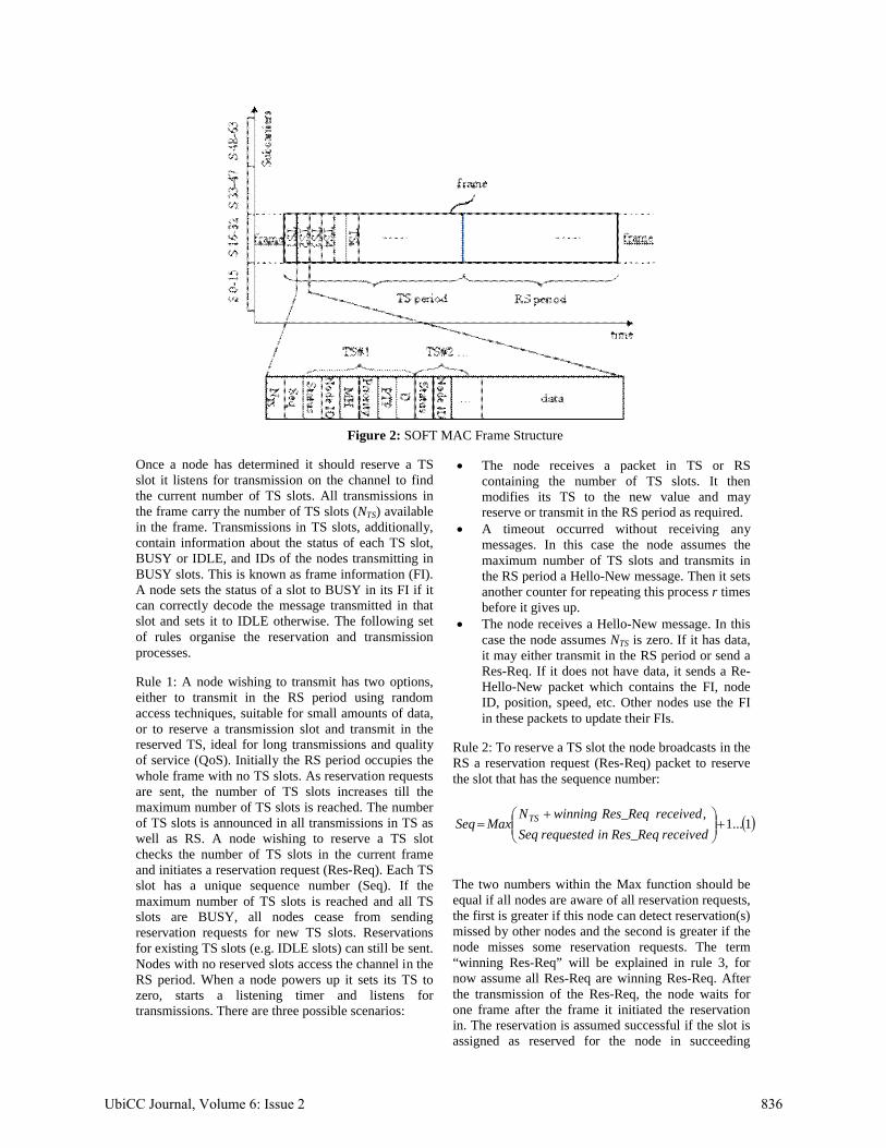
Figure 2: SOFT MAC Frame Structure
Once a node has determined it should reserve a TS slot it listens for transmission on the channel to find the current number of TS slots. All transmissions in the frame carry the number of TS slots (NTS) available in the frame. Transmissions in TS slots, additionally,contain information about the status of each TS slot, BUSY or IDLE, and IDs of the nodes transmitting in BUSY slots. This is known as frame information (FI). A node sets the status of a slot to BUSY in its FI if it can correctly decode the message transmitted in that slot and sets it to IDLE otherwise. The following set of rules organise the reservation and transmission processes.
Rule 1: A node wishing to transmit has two options, either to transmit in the RS period using random access techniques, suitable for small amounts of data, or to reserve a transmission slot and transmit in the reserved TS, ideal for long transmissions and quality of service (QoS). Initially the RS period occupies the whole frame with no TS slots. As reservation requests are sent, the number of TS slots increases till the maximum number of TS slots is reached. The number of TS slots is announced in all transmissions in TS as well as RS. A node wishing to reserve a TS slot checks the number of TS slots in the current frameand initiates a reservation request (Res-Req). Each TS slot has a unique sequence number (Seq). If the maximum number of TS slots is reached and all TS slots are BUSY, all nodes cease from sending reservation requests for new TS slots. Reservations for existing TS slots (e.g. IDLE slots) can still be sent.Nodes with no reserved slots access the channel in the RS period. When a node powers up it sets its TS to zero, starts a listening timer and listens for transmissions. There are three possible scenarios:
The node receives a packet in TS or RS containing the number of TS slots. It then modifies its TS to the new value and may reserve or transmit in the RS period as required.
A timeout occurred without receiving any messages. In this case the node assumes the maximum number of TS slots and transmits in the RS period a Hello-New message. Then it sets another counter for repeating this process r times before it gives up.
The node receives a Hello-New message. In this case the node assumes NTS is zero. If it has data, it may either transmit in the RS period or send a Res-Req. If it does not have data, it sends a Re-Hello-New packet which contains the FI, node ID, position, speed, etc. Other nodes use the FI in these packets to update their FIs.
Rule 2: To reserve a TS slot the node broadcasts in the RS a reservation request (Res-Req) packet to reserve the slot that has the sequence number:
1...1,
receivedqRes_ReinrequestedSeq
received Res_ReqwinningNMaxSeq TS
The two numbers within the Max function should beequal if all nodes are aware of all reservation requests, the first is greater if this node can detect reservation(s)missed by other nodes and the second is greater if the node misses some reservation requests. The term“winning Res-Req” will be explained in rule 3, for now assume all Res-Req are winning Res-Req. After the transmission of the Res-Req, the node waits for one frame after the frame it initiated the reservation in. The reservation is assumed successful if the slot is assigned as reserved for the node in succeeding
UbiCC Journal, Volume 6: Issue 2 836

received FIs, the reservation is also assumed successful if Seq = 1 and no FI was received during the waiting period. The reservation is assumed to have failed otherwise. A node may also request a slot which has been marked as IDLE in all received FIsfor k consecutive frames. All Res-Req packets containFI of current and new successfully reserved TS slotswithin the same frame. If a node has a TS slot and wishes to reserve another, this can be done either via the RS period or by signalling in the TS period.
To illustrate rule 2 assume there are 4 TS slots and 2new nodes (1 and 2) wishing to reserve. Let the first node (1) accesses the RS slots without collision, it then announces the number of TS slots as 4 and requests slot number 5. The second node accessing the RS slots will announce the number of TS slots as 5, the frame information (FI) will indicate TS with Seq = 5 is reserved for node (1), and request TS number 6. In the next frame the nodes at TS 1 to 4 will also announce the slot allocation and increase the number of TS slots, however the new nodes will delay their transmission for this frame to avoid any hidden terminals as will be explained in rule 8. Note that if a collision occurred the reservation either fails and the process is restarted or one of the reservations is successfully detected by some node(s) and is announced in subsequent transmissions or the two reservations were detected, each by a different group of nodes. In this case these groups announce two different reservations for the same slot. This is resolved using rule 8.
Rule 3: A node belonging to two cells and having a TS slot in cell 1 may reserve a TS slot in cell 2 and keep the reserved slot in cell 1 if the new slot satisfies one or more of the following conditions: It has the same sequence number as its reserved
TS in cell 1 The equivalent TS slot in the frame of cell 1 is
marked as point-to-point (PTP) and this node is not the destination
It is in the RS period of cell 1
If more than one slot satisfies different conditions, the slot satisfying the first conditions is preferred. If two or more slots satisfy identical conditions one is chosen randomly. If no slot satisfies the conditions, it is not possible to reserve a new slot in cell 2, the node needsto release the slot in cell 1 before reserving in cell 2.
If a TS slot is free, even if a reservation request has been sent for it by another node, or BUSY but a must-have (MH) flag is not set, a node may send a reservation request for this slot with the MH flag set.This is used only by nodes belonging to two cells. The slot is then allocated to one of the nodes that have set the MH flag on a first come first serve basis and the MH status of the slot in the FI is set. The node that occupied, or first requested, the slot with the MH flagunset is allocated another slot if possible. Nodes
which have requested the slot and set the MH flag but failed the first come first serve process are not allocated a slot. These are ‘failing’ Res-Req and all the others are ‘winning’ TS-Req. The MH statusremains set as long as the node has reserved slots in the frames of two, or more, cells otherwise it is unset. A node may have several slots in the same frame but only one of them can have the MH flag set. This rule provides seamless handoff between cells. The conditions for reserving a slot in a new cell ensure the node does not miss any broadcast messages in the original cell since typically a node cannot transmit and receive at the same time.
Rule 4: If a node correctly decodes a packet in a TS slot, it announces this slot as reserved for the transmitting node. Otherwise it announces the slot as IDLE.
Rule 5: A broadcast transmission is assumed successful if all the frame information (FI) received by the source indicate the slot is reserved for it. If this is not true a collision is assumed, the slot is released and a new reservation is started.
Rule 6: A node modifies its FI information to include any new TS slots if it receives an FI with the new slot(s) allocated to certain destination(s). This is a case when a node cannot sense the reservation but another node within the cluster can (hidden terminal problem).
Rule 7a: In the FI each TS slot has a delete (D) flag. An active node broadcasts a delete request by setting in its FI the D flag of a slot to delete the assignment of that unused TS slot to an inactive node if for qconsecutive frames (q > k) the slot was sensed idle and declared IDLE in all received frame information (FI). Each node checks its own FI to determine the slots it can occupy in the frame and broadcasts this in its own transmission. A node declares it can occupy a slot if it is IDLE in all received FI and on its own FI.
Rule 7b: The active node that broadcasted the delete request rearranges the allocation of slots to nodes so that last TS slot becomes IDLE and broadcasts the new slot assignment to the active nodes in the next frame. The number of TS slots is reduced for each unassigned TS slot while the RS period increases i.e. the last TS slot(s) becomes part of the RS period. If a node declares it cannot occupy a slot (e.g. because a neighbour indicates slot is BUSY) then the slot cannot be re-assigned to it but can be re-assigned to another node that can occupy it. If a slot cannot be re-assigned, the delete counter is reset to q.
Rule 8: An active node with no reserved TS sets a timer if it detects two successful reserve requests for the same TS slot (at least the second request has the MH flag unset, which may be generated by a hidden node). Let’s call this case double reservation. The
UbiCC Journal, Volume 6: Issue 2 837

node reduces the timer (Gateway counter) to half itscurrent value for each additional successfully detectedreserve request for the same slot. Note that a reserve request refers to reservations via Res-Req messages in the RS as well as new TS assignments in the FI of other nodes. If the Gateway counter expires, the node sends a message (Gateway-Hello). In the Gateway-Hello message the number of TS slots is set to be:
)2.....(
,_
seservationRdoublereceivedof No
nodeinNqResReinNMaxN TTST
The FI field in the Gateway-Hello message arranges the assignment of the slots to nodes based on a first come first served basis. If the Gateway already has a reserved slot it can defer the transmission and transmit in its TS slot. The node resets its Gateway counter and does not transmit a Gateway-Hello message if there are no more free TS slots or if all the following conditions became true:1. A Gateway-Hello message or FI sent from
another node is received2. The received Gateway-Hello or FI has equal or
greater NTS
3. The received Gateway-Hello or FI assigned slots to all the nodes requesting new reservations
To illustrate rule 8 consider the clusters shown in Fig (3). The nodes in Fig (3) are represented by circles while the ovals are clusters. Assume each node within a cluster can correctly receive packets from all the nodes within the same cluster but not from nodes inother clusters. For instance node 2 can receive from 4, 5 and 6 but not from the other nodes while 4 can sensethe transmission from all the nodes. Let the number of TS slots = 0 and assume nodes 1, 2 and 3 each want to reserve a slot and each of them successfully accessed the RS period without collision. Since none of them can sense the reservation request of the others they will all request the same slot i.e. TS 1. Let node 1 bethe first to transmit a reservation, this will be sensed by nodes 4, 6 and 7. Then node 2 broadcasts a reservation for the same slot. Nodes 4 and 6 both nowdetect a double reservation and each of them sets its own Gateway counter to resolve this double reservation while 5 and 7 have only detected a single reservation. Now node 3 announces its reservation thus nodes 5 and 7 start their Gateway counters since they detected double reservation, however 4 now has detected 3 reservations for the same slot, so it reduces its counter by half to access the channel before nodes 5, 6 and 7 and announces an NTS of 3, assigned to nodes 1, 2 and 3 respectively. Nodes 5, 6 and 7 receiving the FI of node 4 and realising the NTS
announced is 3, which is greater than their NTS (= 2), and all reservation requests have been resolved, ceasefrom transmitting the Gateway Hello packet and update their FIs. Note that even if node 4 does not exist and, for instance, node 6 accessed the channel, nodes 5 and 7 will become aware of the additional
hidden node from the FI of node 6 and reduce their counters by half. Now nodes 5 and 7 both have the information of all the reserving nodes and any one of them upon announcing the reservation will reset the other. If node 4 has a TS reserved then it simply waitsfor its reserved TS to announce the slot allocationwithout the need to set a counter.
Figure 3: Illustration of double reservations
3.3 Point-to-Point Transmission in SOFT MAC
For point-to-point (PTP) communications we adapt the approach proposed in [7] to work with our proposal. A Point-to-Point (PTP) flag is used to differentiate between a broadcast transmission and a PTP transmission.
Rule 9: A node sets the PTP flag for a TS slot in its own FI to 1 if:1. The message received in that slot is a broadcast
message or2. It is the destination of this packet in PTP
communications
The PTP flag is set to 0 otherwise. If the destination does not have a reserved slot it must reply with an acknowledgement packet (explicit ACK) in the same TS slot. The transmitter can determine whether to expect an ACK or not by checking its FI, if the destination has a reserved BUSY slot the ACK packet is not expected but the PTP flag of the transmitter’s slot in the FI of the destination is checked and the transmission is successful if PTP equals 1 (implicit ACK). If the destination has no TS slot an ACK is expected and the transmitter must adjust its packet length so that the duration of the packet + ACK + any waiting time does not exceed the TS slot duration.
Rule 10: A TS slot can be accessed for PTP communication if the following conditions are satisfied:1. The PTP flag in set to 0 in all received FIs2. The FI received from the intended destination
declares the slot as IDLE3. An ACK cannot be sensed in the specified slot.
The first and third conditions ensure that the ongoing communication in the slot is PTP and the destination
1
2
3
4 56
7
UbiCC Journal, Volume 6: Issue 2 838

of this transmission is not within the range of the transmitter. The second condition ensures the new destination is not within the range of the transmitter or the receiver of the original transmission.
Rule 11: The transmission is considered successful if the slot is set to BUSY with the correct node ID and PTP set in the FI of the destination terminal or if an ACK was received; otherwise it is assumed that the transmission has failed.
3.4 Priority in SOFT MAC
We adapt the 2-bits priority field of the IEEE 802.11e standard to identify the type of traffic in a given TS slot [15, 16]. Nodes then use this field, along with the MH flag, to request TS slots occupied by lower priority traffic. Table (1) shows the proposed priority scheme in descending order.
The priority of the traffic transmitted in the TS is announced in the header. If a node wishes to overtake a TS slot, it checks its priority against that announced in the TS. If its traffic has higher priority it may send a reservation request and the TS will be reassigned to it. If the priority is lower, the reservation will be declined. The MH flag has the highest priority since it is indicates the node is moving from one cell to another, thus it is necessary to perform the handoffbetween cells. Other than the handoff case, reservation requests for BUSY TS slots are not sent unless the maximum number of TS slots is reached.
Table (1): Priority in SOFT MAC
MH flag Priority Type of Traffic1 X Handoff0 3 Safety0 2 Road Traffic data0 1 Multimedia0 0 Best Effort
4 IMPLEMENTATION OF SOFT MAC USING 802.11
The 802.11 standard has two modes of operation, the Distributed Co-ordination Function (DCF) and thePoint Co-ordination Function (PCF). PCF is implemented using an Access Point (AP). In PCF there are two intervals, Contention Period (CP) and Contention Free Period (CFP). During the CP, nodes access the channel using DCF in a distributed manner without the intervention of the AP. In the CFP, the AP polls the nodes for data. A node must register itself with the AP to enter the polling list [14-16].
There are four basic time units in 802.11, the slot time (), Short Inter Frame Space (SIFS), Priority Inter Frame Space (PIFS) and Distributed Inter Frame Space (DIFS). The slot time, the smallest of all of them, is the time unit used for the back-off counters.
SIFS is the smallest of the Inter Frame Spaces and is used between a transmission and its acknowledgement as well as in-between request to send/clear to send handshakes (RTS-CTS-data-ACK). PIFS (=SIFS+) is used only by the AP while the DIFS (=SIFS+2) is used by all nodes [14].
In PCF the AP waits for the channel to be idle for a PIFS before broadcasting a beacon packet. This beacon announces the start of the CFP period and indicates the channel will be busy for the maximum CFP period. All nodes then set their Network Allocation Vector (NAV) to the channel busy duration specified in the beacon. During this period no node will attempt to access the channel unless the AP polls it for data. After the AP finishes polling (even if the maximum CFP is not reached), it broadcasts another beacon that terminates the CFP (starts the CP). The nodes then reset their NAV and contend for the channel using the DCF [16].
SOFT MAC can be easily implemented using the PCF features. When the TS period starts, the node that reserved TS 1 waits for a PIFS before transmission. This will ensure the node gains access to the channel before any other node. Subsequent nodes follow the same strategy to access their TS slots. All nodes transmitting in the TS will broadcast the time left in the TS period, number of TS slots and sequence number of current slot. This will be used by nodes unaware of the number of slots to update their NAV as well as number of TS slots and hence do not attempt to access the channel during the TS period. After the TS period, all nodes must wait for a DIFS before attempting to access the channel. Although the PCF mode is optional, the 802.11 standard specifies that all nodes must be able to co-operate with the PCF function even if they do not support the polling service of the AP [16]. This ensures that SOFT MAC can coexist with 802.11. Fig (4) shows this access scheme. In the next section we analyse the saturation throughput of this implementation.
Figure 4: SOFT MAC implementation using 802.11standard
5 THROUGHPUT ANALYSIS OF SOFT MAC
In this section we theoretically analyse the performance of the TDMA protocol of SOFT MACfor one cell and compare it to the basic access mode of 802.11 standard. The following assumptions will be used for our analysis: Both SOFT MAC and 802.11 have the same
bandwidth (20MHz) and number of subcarriers (64) per cell.
The data rate is 6Mbps
DIFSPIFS TS 3PIFS RS PeriodTS 2TS 1
UbiCC Journal, Volume 6: Issue 2 839

Nodes share a single channel SOFT MAC is implemented using 802.11 as
described in the previous section The frame duration (Tframe) is fixed and equal to
100ms All transmissions start and finish within the
frame (i.e. no transmission extends between two frames)
We adopt the specifications for 802.11a (5.8GHz), since 802.11p specifications are based on 802.11a
All TS slots have been reserved Implicit ACK is used The nodes always have data to transmit
(saturation throughput) No hidden terminals
4.1 Throughput of the TS period
Since the TS period is contention free, the throughput (STS) is given by:
)3...(.........._ timeWaitrate
DataHeaderrate
DataSTS
Where Data is the total transmitted data, rate is the data rate, Header is the total header (control bits) and Wait_time is the total channel idle time (PIFS). The header in each TS slot is calculated as:
)4..(
_
DestIDFrDUFrCONSeqNo
DNodeIDPMHPTPstatusNH
TS
TSTS
NTS is the number of TS slots. The other parameters (based on 802.11 standard [14]) are listed in Table (2).Since there are NTS slots per frame, the parameters of Eq. (3) are given by:
PIFSNtimeWait
PNData
HNHeader
TS
TSTS
TSTS
_
)5......(........................................
Where PTS is the average payload size per TS slot.The TS period duration (TTS) should satisfy:
)6.......(_ timeWait
rate
DataHeaderTT TSframe
After the TS period all nodes wait for a DIFS before attempting to access the channel. Therefore the RS period duration (TRS) is given by:
)7....(..............................DIFSTTT TSframeRS
Table (2): Fields of TS header
Field Use Number per TS slot
Size (bits)
status TS slot status (BUSY/IDLE)
NTS 1
PTP Point-To-Point flag
NTS 1
MH_P MH/Priority of each slot
NTS 1+2
D Delete flag NTS 1NodeID MAC Address
of node transmitting in a
TS slot
NTS 48
NoTS Announces current number
of TS slots
1 8
Seq Sequence No. of current TS slot
1 8
FrCON Frame Control 1 16
FrDU Frame Duration (Time left in TS
period)
1 16
DestID MAC address of the destination
of the slot
1 48
Nodes access the RS period via the DCF. Eq. (4) to Eq. (7) are the key to the design of the frame as they specify the possible number of TS slots for a specific frame duration, TS duration and packet size. As the packet size increases, the possible number of TS slots decreases while improving the throughput since less header and wait time is needed. On the other hand a smaller number of TS slots means less nodes can reserve TS slots.
4.2 Throughput of the RS period
The theoretical saturation throughput (SRS) of the RS period is the throughput of the DCF. This has been analysed in [1] and closed form expressions were obtained as:
8.............
21121
212mppWWp
p
9............................................11 1 np
10............................................11 ntrP
11.........................................11
1 1
n
n
sn
P
)12....(
1..1
..
cstrsstrtr
trsRS TPPTPPP
PEPPS
13... DIFSACKSIFSPEHTs
14...........................* DIFSPEHTc
UbiCC Journal, Volume 6: Issue 2 840

Where is the probability that a node transmits in a randomly chosen slot time, p is the probability of collision. These are found by solving Eq. (8) and Eq. (9). W is the window size, m defines the maximum window size, n is the number of nodes, Ptr is the probability of at least one transmission in the considered slot time, Ps is the probability of successful transmission, is the duration of a slot, Ts
is the average channel busy time due to successful transmission, Tc is the average channel busy time due to collision, H is the packet header, E[P] and E[P*] are the average packet durations for successful transmission and collision respectively and is the propagation delay [1]. Combining the throughput of the TS with the throughput of the RS, the total throughput of the frame is then:
)15.....(....................frame
RSRSTSTS
T
TSTSS
Note that if the RS period is smaller than the time required to transmit a packet and its ACK, we set the throughput of the RS period to zero.
6 RESULTS
In this section we analyse the protocol and compare its performance to the basic access method of DCF. Fig (5) shows the efficiency (= data packet size) and number of TS slots versus the payload size assuming TS duration = Tframe. As the payload size increases the number of possible TS slots drops thus reducing the overhead and wait time and improving efficiency but the number of nodes that can access the channel becomes smaller. Therefore there is a trade-off between efficiency and number of TS slots.
Figure 5: Slot Efficiency and No. of TS slots vs. Payload Size
Fig (6) shows the performance of SOFT MAC versus the number of nodes for TS durations starting from 0
(pure DCF) to the maximum possible slots in Tframe
duration (pure TDMA). The payload size is 2312 bytes which is the maximum payload in 802.11 [14]. The performance improves as the TS duration increases reaching approximately 90% for pure TDMA but then only 29 nodes can access the channel. Reducing the payload to 1000 bytes increases the maximum number of slots to 53 but the maximum achievable throughput is less than 75% as shown in Fig (7).
Figure 6: Throughput vs. No of Nodes(Payload size = 2312B)
Figure 7: Throughput vs. No of Nodes(Payload size = 1000B)
Finally Fig (8) shows the performance of SOFT MAC versus the payload size for a network of 50 nodes. For a small payload size, the number of slots is high, thus, the header becomes a considerable percentage of the packet and the throughput drops. As the payload increases, the throughput increases but the possible number of TS slots decreases. A payload size of approximately 500 bytes is the threshold for SOFT MAC to perform better than 802.11.
UbiCC Journal, Volume 6: Issue 2 841

Figure 8: Throughput vs. Payload Size (50 Nodes)
7 CONCLUSION
In this paper we introduced and analysed a new MAC protocol for VANET known as SOFT MAC. The protocol divides the roads into cells and allocates each cell a group of subcarriers. Within the cell, the nodes share the available subcarriers using a combined TDMA-CSMA protocol. Time is split into frames and each frame has two periods. The first period consists of transmission slots (TS period) and is accessed after reservation. The second period is the reservation (RS) period and is accessed using a random access technique (DCF). The RS period is used to send reservation requests as well as data. A mathematical analysis of the saturation throughput was derived and used to analyse the protocol. Compared to 802.11 basic access, SOFT MAC shows improvement in throughput as long as the payload size exceeds 500 bytes. As the TS period increases the performance improves but the number of nodes that can access the channel is reduced.
8 REFERENCES[1] G. Bianchi, "Performance Analysis of the IEEE 802.11
Distributed Coordination Function," IEEE Journal on Areas in Communications, vol. 18, pp. 535-547, March 2000.
[2] H. Fattah, "Analysis of the Channel Access Mechanism in IEEE 802.11 Wireless Local Area Networks," in IEEE Pacific Rim Conference on Communication, Computing and Signal Processing, Aug 2007, pp. 74-77.
[3] L. Kleinrock and F. A. Tobagi, "Packet Switching in Radio Channels: Part I-Carrier Sense Multiple-Access Modes and Their Throughput-Delay Characteristics," IEEE Transactions on Communications, vol. COM-23, pp. 1400-1416, Dec 1975.
[4] L. Kleinrock and F. A. Tobagi, "Packet Switching in Radio Channels: Part II-Carrier Sense Multiple-Access Modes and Their Throughput-Delay Characteristics," IEEE Transactions on Communications, vol. COM-23, pp. 1417-1433, Dec 1975.
[5] S. V. Bana and P. Varaiya, "Space Division Multiple Access (SDMA) for Robust Ad hoc Vehicle Communication Networks," in IEEE Intelligent Transportation Systems Conference, Oakland (CA) USA, 25-29 Aug 2001, pp. 962-967.
[6] J. J. Blum and A. Eskandarian, "A Reliable Link-Layer Protocol for Robust and Scalable Intervehicle
Communications," IEEE Transactions on Intelligent Transportation Systems, vol. 8, pp. 4-13, March 2007.
[7] F. Borgonovo, A. Capone, M. Cesana, and L. Fratta, "ADHOC MAC: New MAC Architecture for Ad Hoc Networks Providing Efficient and Reliable Point-to-Point and Broadcast Services," Wireless Networks, vol. 10, pp. 359-366, 2004.
[8] Y. Gunter, B. Wiegel, and H. P. Grossmann, "Cluster-based Medium Access Scheme for VANETs," in IEEE Intelligent Transportation Systems Conference, Seattle, USA, Oct 2007, pp. 343-348.
[9] S. Katragadda, C. N. S. Ganesh Murthy, M. S. Ranga Rao, S. Mohan Kumar, and R. Sachin, "A decentralized location-based channel access protocol for inter-vehicle communication," in The 57th IEEE Semiannual Vehicular Technology Conference, 2003. VTC 2003-Spring, 22-25 April 2003, pp. 1831-1835.
[10]T.-K. Liu, J. A. Silvester, and A. Polydoros, "Performance Evaluation of R-ALOHA in Distributed Packet Radio Networks with Hard Real-time Communications", IEEE 45th Vehicular Technology Conference,1995.
[11]X. Zhang, H. Su, and H.-H. Chen, "Cluster-Based Multi-Channel Communications protocol in Vehicle Ad Hoc Networks," in IEEE Wireless Communications, Oct 2006, pp. 44-51.
[12]F. Borgonovo, A. Capone, M. Cesana, and L. Fratta, "ADHOC MAC: a new, flexible and reliable MAC architecture for ad-hoc networks," in IEEE Wireless Communications and Networking, 2003, pp. 965-970 vol.2.
[13]C. Chih-Min, S. Jang-Ping, and I. C. Chou, "A load awareness medium access control protocol for wireless ad hoc network," in IEEE International Conference on Communications, 2003, pp. 438-442.
[14]B. O'Hara and A. Petrick, IEEE 802.11 Handbook A Designer's Companion. New York: Institute of Electrical and Electronics Engineers Inc., 1999.
[15]N. Reid and R. Seide, 802.11 (Wi-Fi) Networking Handbook. USA: McGraw-Hill, 2003.
[16]J. Larocca and R. Larocca, 802.11 Demystified. USA: McGraw-Hill, 2002.
[17]Y. Zang, L. Stibor, B. Walke, H. J. Reumerman, and A. Barroso, "A Novel MAC Protocol for Throughput Sensitive Applications in Vehicular Environments," in IEEE Vehicular Technology Conference, 22-25 April 2007, pp. 2580-2584.
[18]X. Ma, P. Hrubik, H. Refai, and S. Yang, "Capture Effect on R-ALOHA Protocol for Inter-Vehicle Communications", IEEE 62nd Vehicular Technology Conference,25-28 Sept 2005.
[19]F. Borgonovo, L. Campelli, M. Cesana, and L. Fratta, "Impact of User Mobility on the Broadcast Service Efficiency of the ADHOC MAC protocol," in IEEE 61st Vehicular Technology Conference, 30 May -1 June 2005, pp. 2310-2314.
UbiCC Journal, Volume 6: Issue 2 842


