PAPER • OPEN ACCESS Design of Area Efficient Filter Bank ...
20
Journal of Physics: Conference Series PAPER • OPEN ACCESS Design of Area Efficient Filter Bank for Digital Hearing Aids To cite this article: Narem Mohith Reddy and M Suchetha 2020 J. Phys.: Conf. Ser. 1716 012049 View the article online for updates and enhancements. This content was downloaded from IP address 106.195.40.208 on 06/08/2021 at 08:07
Transcript of PAPER • OPEN ACCESS Design of Area Efficient Filter Bank ...

Journal of Physics: Conference Series
PAPER • OPEN ACCESS
Design of Area Efficient Filter Bank for Digital Hearing AidsTo cite this article: Narem Mohith Reddy and M Suchetha 2020 J. Phys.: Conf. Ser. 1716 012049
View the article online for updates and enhancements.
This content was downloaded from IP address 106.195.40.208 on 06/08/2021 at 08:07

Content from this work may be used under the terms of the Creative Commons Attribution 3.0 licence. Any further distribution
of this work must maintain attribution to the author(s) and the title of the work, journal citation and DOI.
Published under licence by IOP Publishing Ltd
National Science, Engineering and Technology Conference (NCSET) 2020Journal of Physics: Conference Series 1716 (2021) 012049
IOP Publishingdoi:10.1088/1742-6596/1716/1/012049
1
Design of Area Efficient Filter Bank for Digital Hearing Aids
Narem Mohith Reddy1 and M Suchetha
2*
1School of Electronics Engineering, VIT Chennai, India 2Division of Healthcare Advancement, Innovation &Research, VIT Chennai, India
E-mail:[email protected], 2*[email protected]
Abstract. The objective of the work scheduled is to design an area-efficient filter bank in a digital hearing aid by making use of Verilog HDL for functional verification, Synthesis & Physical Design in Cadence- Genus & Innovus respectively using ASIC design flow. Hypoacusis is a medical term which is well referred to as hearing impairment is a total or partial incompetence to hear. Around 466 million people live with Hypoacusis worldwide this is over 5% of the world's populace. Hearing Aid is an Acoustoelectric Transducer which selectively enhances signal to ear to reimburse hearing loss. As technology is advancing day by day digital hearing aids are more adaptive, small and lightweight. The main block of the hearing aid is a filter bank which performs sound decomposition. To design a filter bank, it requires a precise intelligence of distinct digital signal processing approaches used in hearing aids among them the most important is to design a filter in which FIR, IIR, IFIR are crucial, which extracts signal within frequency bands. The proposed design area is minimized by 70.53%. thereby the size of the device is drastically reduced. The proposed design has an added advantage of lower power and delay.
1. Introduction
Hearing impairment which debilitates communication- a vital human function, is a key factor of inability notably in aged people which is ranked as the third most regular health issue effecting nature and relations of the life. People who is suffering from hearing impairment over 40 decibels in the enhanced hearing ear in grown-ups, over 30 decibels in the enhanced hearing ear in kids are examined has inability in hearing. WHO Chronicle states- "Over 5% of the world's population (466 million people) has disabling hearing impairment including 432 million grown-ups and 34 million kids. This has increased from 360 million people five years ago These eye-opening statistics further envisages an enormous increase in the count of hearing-impaired subjects. These 'Hard of Hearing' people can take advantage from hearing aids.
However, current production of hearing aids meets below 10% of global need and below 3% of developing countries' needs. It is also estimated by WHO that by 2050 over 900 million people or one in each ten people going to have disabling hearing impairment. Lack of treatment to this disorder might lead to Alzheimer's disease or hearing-impaired people might develop Dementia. The unaddressed hearing loss even costs countries an estimated US$ 750 billion annually in direct health costs and fall of productivity. Though hearing aids can easily compensate for the majority of hearing losses, they are widely available only in the most highly developed countries. In United States, out of the hardly 16% of hearing impaired (aged between 20-69 years) and 30% of hearing- disabled (above 70 years) who can be benefitted using hearing aids actually wears it.

National Science, Engineering and Technology Conference (NCSET) 2020Journal of Physics: Conference Series 1716 (2021) 012049
IOP Publishingdoi:10.1088/1742-6596/1716/1/012049
2
The alarming growth rate of the hearing impaired and terrifying human tribulations associated with it indicates the dire need to address the research in augmenting the performance of existing hearing aids to ensure that it overcomes the bottlenecks which restricts the hearing impaired from using hearing aids and thus minimize the loopholes between the potential and actual hearing aid users leading to betterment of community. Rest of the paper is organized as follows: Section II gives an overview of types of hearing loss, different auditory problems faced by hard-of-hearing people, what are causes of different hearing loss with cure and how hearing aid plays a crucial role in overcoming this disheartening disability of hearing. This section also gives a comparative analysis of the advanced hearing aids based on their features and performance. Section III elaborates selection of filter bank for a hearing aid.
Filter bank and types of filter banks and comments of suitability of filter type for hearing aid application. Section IV presents a review of the proposed design in which performance parameters to be considered for filter design and evaluation from the perspective of hearing instruments. Section V throws light on Synthesis of the Interpolated FIR filter bank which can enable hearing aids to become customized and tailor made as per the hearing profile of the patients and further scrutinizes the filter parameters that can be optimized in IFIR filter bank. Section VI presents a bird's eye view of the Synthesis of the proposed design in the ASIC design flow (semi-custom design) of the proposed IFIR filter bank design for hearing aid application and in additionally it provides synthesis of the design Section VII elaborates the elaborates the overall performance parameter review on the proposed work. Section VIII presents results and discussions on the performance improvement of hearing aids.
2. Hearing Aids & Its Contribution towards Hearing Loss
Hearing impairment is a usual problem that regularly created with age oris caused by rehashed exposure to loud noises. Hearing impairment is the result of sound signals not arriving at the cerebrum of brain. Hearing impairment can happen unexpectedly, but usually develops slowly. General signs of hearing impairment can incorporate trouble in hearing others clearly and having misconception what they say, listening to music with the volume turned up higher than other people require and requesting that individuals rehash what they state.
Basically, a patient can experience the ill effects on an ear from three types of hearing impairment. Patients who are suffering with sensory neural hearing loss caused by damage to the delicate hair cells inside the internal part of an ear or damage to the aural nerve; this occurs naturally with age or as a result of injury. A portion of the aural nerves do not appropriately reverberate with their designated frequencies and are not able to send short pulses to the brain. The other kind is conductive hearing loss at the point when sounds can't go from your external ear to your inward ear frequently due to a blockage, for example, earwax stick ear or a development of fluid from an ear contamination or on account of a perforated ear drum or as a consequence of a perforated ear drum or disorganization of the hearing bones. It's likewise feasible to have both sensory neural loss and conductive loss. This is called as mixed hearing loss. Some people are brought into the world with hearing impairment, but most part of the cases develop as you get aged.
The level of hearing impairment of an individual can be gauged by taking their audiometry test. The audiogram obtained as a result of this hearing test highlights the hearing capability of patient over a varied range of frequencies by measuring patient's hearing threshold with respect to frequency. The frequency range of hearing for a normal human is 20Hz to 20 kHz. Human hearing is most sensitive in the range of 1 kHz to 4 kHz [1].

National Science, Engineering and Technology Conference (NCSET) 2020Journal of Physics: Conference Series 1716 (2021) 012049
IOP Publishingdoi:10.1088/1742-6596/1716/1/012049
3
Figure 1. Structure of Human Ear.
This auditory evaluation of hearing- weakened is done at each octave viz. 250Hz, 500Hz, 1kHz, 2kHz,4kHz and 8kHz owing to the fact that human ear responds to sounds in logarithmic manner and shows the mildest sound that the person can hear at different frequencies. The audiogram provides a visual representation of hearing capacity of hearing challenged for varying frequencies and thus enables audiologist to interpret the hearing loss to be of which type depending on their hearing threshold as shown in Figure 2 [2][3].
Figure 2. Types of Hearing Loss with Hearing Threshold and their Effect.
Hearing aids have huge potential to enable hearing impaired with mild[4] to extreme hearing impairment to listen and communicate in a better manner. Digital Hearing Aid compensates the reduced sensitivity of ear and thus improves hearing quality of patients with hearing misfortune. Digital Hearing Aids are composed with microphones and the signal is converted using analog to digital converter, Filter bank which after decomposition multiplied with weights and sent through low and high pass filters, and reconstruct the signal and converts the signal using digital to analog converter and gives the sound which is shown in Figure 3.

National Science, Engineering and Technology Conference (NCSET) 2020Journal of Physics: Conference Series 1716 (2021) 012049
IOP Publishingdoi:10.1088/1742-6596/1716/1/012049
4
Figure 3. Block Diagram of Digital Hearing Aid.
Hearing It is entrenched fact that when speech is heard and perceived at correct amplitude, it becomes more intelligible. In line with this, the fundamental role of hearing aid is to amplify and process the input sound to provides best possible match to the audiogram of the patient and ameliorate their problems related to hearing impairment. Today's modern digital hearing aids have variety of features being provided by manufacturers like:
• Reprogrammable • Adaptive • Multiple listening modes • Best sound quality with noise cancellation • Small & light in weight However, the adoption rate of hearing aid is insignificant as compared to the rate at which
advancements are happening in hearing aids. This is a clear indicator that people with hearing misfortune still faces a variety of problems which hampers the adoption of hearing aid. The Challenges in hearing aid design for researchers include:
• Less hardware Complexity • Noise Reduction • Improvement in speech intelligibility & speech enhancement • Reduce size • Low power dissipation because of portability • Low Distorted output at amplifier with high efficiency • Improved sound quality [5]
3. Filter Banks in Hearing Aids
The list of key design challenges of hearing aid highlighted in Section II evidently shows that the hearing aid which aims to benefit the masses with this sensory disturbance needs to be personalized in the sense that it is able to provide different decomposition schemes to serve the varying needs of different patients. It should be more natural and humanized. Filter bank is the holy grail of Digital hearing aid. This inevitable part of hearing aid is a group of parallel low pass, high pass and band-pass filters. It splits given sound signals in different sub-bands [6] which is illustrated in Figure 6.
After decomposing into different bands, the selective gain is provided to each band to ensure better matching to audiogram. The filter banks broadly delineate input sound signal characteristics from perspective of different patients and thus ensure auditory compensation in Hearing aids. Normally frequencies ranging from 125 Hz to 8 KHz are considered to be the average normal hearing frequency and thus, in most cases, entire frequency range is divided up to 8 KHz. The generic structure of filter bank is depicted in Figure 5.

National Science, Engineering and Technology Conference (NCSET) 2020Journal of Physics: Conference Series 1716 (2021) 012049
IOP Publishingdoi:10.1088/1742-6596/1716/1/012049
5
Figure 4. Standard Architecture of Filter Bank.
Optimized performance of hearing aid greatly depends on the choosing the right type of filter bank. The filter types are categorized below as per their characteristics and critically analysed with respect to their suitability for hearing aid application. The filter bank breaks the input frequency signal into eight frequency bands. These are amplified individually and merged into two frequency bands. Finally, these two signals undergo additional signal processing. The filter bank constitutes about half of the signal processing circuitry in the hearing aid. As illustrated in Figure 6, it consists of a tree structure of filters [7]. For the better performance we need to select the filter in such a way that the filter should meet the design specifications.
Figure 5. 8-Band Tree Structured Filter Bank.
3.1. Analog vs Digital Filter
Some Filter banks can be either analog or digital in type. Digital and analog filters both removes undesirable noise in the signal, but filters work distinctively in the analog and digital domains. However, compared to analog counterpart, digital filters have advantage of programmability, can be more precise in filtering, can also be adaptive to change their filter characteristics, can exploit parallelism, provide higher accuracy, exact linear-phase, can filter low frequencies, time-invariant performance and require relatively smaller silicon area[8]. These advantages, coupled with the advent of VLSI technology, has led to ubiquitous presence of digital filters in hearing aid design [9].

National Science, Engineering and Technology Conference (NCSET) 2020Journal of Physics: Conference Series 1716 (2021) 012049
IOP Publishingdoi:10.1088/1742-6596/1716/1/012049
6
3.2. FIR vs IFIR Filter
In digital Filters, Finite Impulse Response filter shown in Figure. 6[10] is more favourable for hearing aid application because of its stability, linear phase response with no phase distortion, symmetric coefficients and low coefficient sensitivity as against the popular nonlinear phase Infinite Impulse Response (IIR) Filter [11][12]. This further aids in acoustic noise cancellation improvement and preserves phase cues in a better manner for binaural hearing where both hearing aids are worn together and the response of the filter is as in (1) [13].
Figure 6. Architecture of FIR Filter
( ) ∑ ( ) (1)
Figure 7. RTL Schematic of FIR Filter
National Science, Engineering and Technology Conference (NCSET) 2020Journal of Physics: Conference Series 1716 (2021) 012049
IOP Publishingdoi:10.1088/1742-6596/1716/1/012049
7
Figure 8. Simulation result of FIR Filter
However, FIR filter poses high computational complexity and relatively high computational cost in addition to higher stop band attenuation in comparison to IIR filter. With the increasing order of FIR filter bank, the overhead also increases. As compared to IIR, FIR implementation is expensive with respect to hardware and power usage. This problem is further elevated when transition bandwidth of desired filter is very narrow. To ensure linear phase and stability but at no additional complexity, FIR filters realized using transposed direct form can be utilized [14]. It reduces implementation complexity and produces high output with no added complexity. The functional verification of FIR & IIR filters is done in Altera Quartus whose Schematics are shown in Figure 7 and Figure 10 respectively and their respective simulation waveforms are shown in Figure 8 and Figure 11 and the response of the IIR filter is given as (2)
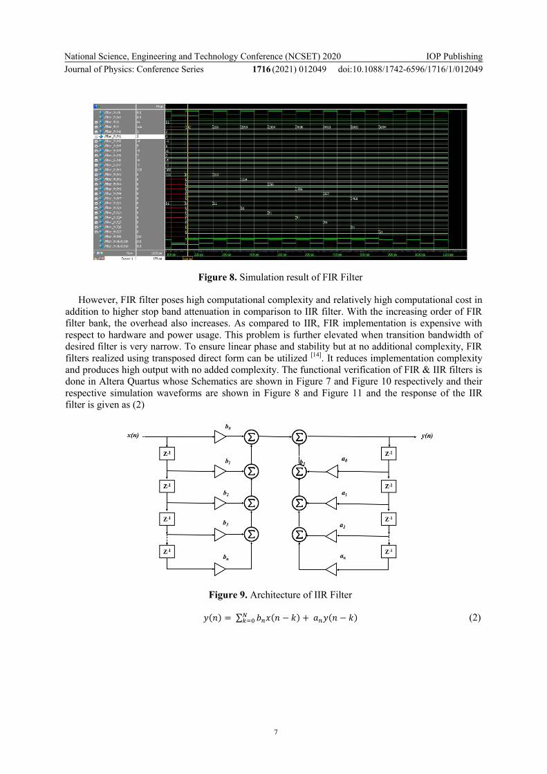
Figure 9. Architecture of IIR Filter
( ) ∑ ( ) ( ) (2)
National Science, Engineering and Technology Conference (NCSET) 2020Journal of Physics: Conference Series 1716 (2021) 012049
IOP Publishingdoi:10.1088/1742-6596/1716/1/012049
8
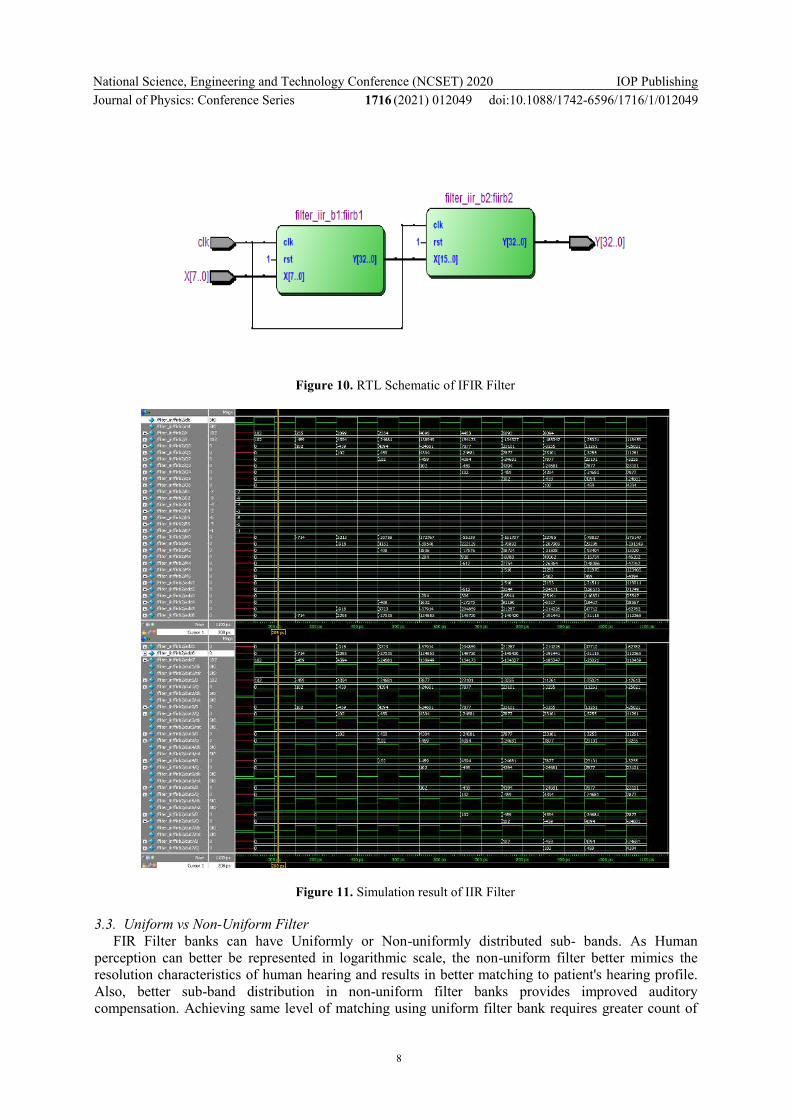
Figure 10. RTL Schematic of IFIR Filter
Figure 11. Simulation result of IIR Filter
3.3. Uniform vs Non-Uniform Filter
FIR Filter banks can have Uniformly or Non-uniformly distributed sub- bands. As Human perception can better be represented in logarithmic scale, the non-uniform filter better mimics the resolution characteristics of human hearing and results in better matching to patient's hearing profile. Also, better sub-band distribution in non-uniform filter banks provides improved auditory compensation. Achieving same level of matching using uniform filter bank requires greater count of

National Science, Engineering and Technology Conference (NCSET) 2020Journal of Physics: Conference Series 1716 (2021) 012049
IOP Publishingdoi:10.1088/1742-6596/1716/1/012049
9
sub-bands [15]. This further adds to hardware complexity and cost. Also, uniform filter bank doesn't take into consideration the unique auditory characteristics of hearing as well as fails to consider auditory features of different hearing loss patients. Hence use of uniform filter bank doesn't give satisfactory performance in terms of audiogram fitting. Owing to this, non-uniform filter gained lots of attention from researchers and are considered as a better choice for hearing aids.
3.4. IFIR Filter
Interpolated FIR Filter is one of the most used non-uniform FIR filter whose advantages are minimum area and delay compared with FIR filter and minimum power dissipation when compared with IIR filter. Since size matters while designing a hearing aid it is an apt choice to choose the IFIR as the filter for designing a filter bank [16]. The architecture [17] & their respective schematics and results are illustrated below and the response is demonstrated as in (3)[18].
Figure 12. Architecture of IFIR Filter
( ) ∑ ( ) ( ) (3)
Figure 13. RTL Schematic of IFIR Filter

National Science, Engineering and Technology Conference (NCSET) 2020Journal of Physics: Conference Series 1716 (2021) 012049
IOP Publishingdoi:10.1088/1742-6596/1716/1/012049
10
Figure 14. RTL Schematic of IFIR Filter
Thus, the extensive analogy of filter bank types in this section suggests that Digital Interpolated FIR Non-Uniform filter banks with plenty of sub bands and bandwidth is an apt choice for digital hearing aid application.
4. The Proposed Design
The proposed 16-band non-uniform filter bank is designed based on an Interpolated FIR scheme served as a vehicle for this research. It is heart of the fully digital hearing aid and it was chosen because it is a realistic industrial example where low power consumption is very important. The existing design which are made with FIR & IIR filters have more area ns power which makes the proposed design unique with optimum delay and area. Hence the design is re-implementation have been fabricated in the same 0.18nm CMOS technology, and the detailed reports optimization in power dissipation, timing, and area has been evaluated.
Figure 15. Area & Power Comparison of FIR, IIR, IFIR filters
The performance parameters report which is demonstrated in Figure 15. and Figure 16. The allocation of each subband in the proposed design is carefully planned such that it maximizes the matching performance for various kinds of hearing impairment. It is widely known that hearing threshold measurements are made at each octave: 250/500/1000/2000/ 4000/ 8000Hz in a standard audiogram[19]. By allocating more bands at low frequencies, it is easy to adjust frequency response of the filter to match audiogram. As hearing impairment mostly happens in the high frequency range,

National Science, Engineering and Technology Conference (NCSET) 2020Journal of Physics: Conference Series 1716 (2021) 012049
IOP Publishingdoi:10.1088/1742-6596/1716/1/012049
11
introducing more bands at high frequencies improves the matching performance as well. With the above two considerations, the proposed filter bank adopts a symmetric band arrangement for the lower and upper eight subbands.
Figure 16. Propagation Delay Comparison of FIR, IIR, IFIR filters
The structure of the proposed work of the filter bank depends on Interpolated FIR Filters. The Sixteen sub bands illustrated in Figure 18. are produced by the splitting of each filter. There are two outputs in both yc(n) and y(n) in Figure 12. The lower branches represent the reciprocating output in favour of yc(n) and the mirrored output over π/2 for y(n)[20].
Figure 17. 16-Band Non-Uniform Interpolated FIR filter bank
Table 1. Cutoff Frequencies of the 16 Sub-bands
Band Low 3dB frequency (Hz)
Upper 3dB frequency (Hz)
1 - 250
2 250 500
3 500 750
4 750 1000
National Science, Engineering and Technology Conference (NCSET) 2020Journal of Physics: Conference Series 1716 (2021) 012049
IOP Publishingdoi:10.1088/1742-6596/1716/1/012049
12
5 1000 1500
6 1500 2000
7 2000 3000
8 3000 4000
9 4000 5000
10 5000 6000
11 6000 6500
12 6500 7000
13 7000 7250
14 7250 7500
15 7500 7750
16 7750 -
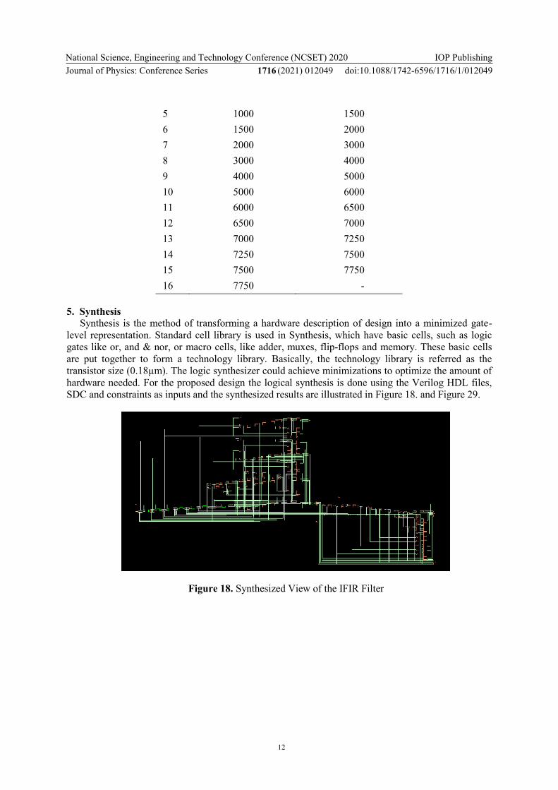
5. Synthesis
Synthesis is the method of transforming a hardware description of design into a minimized gate-level representation. Standard cell library is used in Synthesis, which have basic cells, such as logic gates like or, and & nor, or macro cells, like adder, muxes, flip-flops and memory. These basic cells are put together to form a technology library. Basically, the technology library is referred as the transistor size (0.18µm). The logic synthesizer could achieve minimizations to optimize the amount of hardware needed. For the proposed design the logical synthesis is done using the Verilog HDL files, SDC and constraints as inputs and the synthesized results are illustrated in Figure 18. and Figure 29.
Figure 18. Synthesized View of the IFIR Filter

National Science, Engineering and Technology Conference (NCSET) 2020Journal of Physics: Conference Series 1716 (2021) 012049
IOP Publishingdoi:10.1088/1742-6596/1716/1/012049
13
Figure 19. Synthesized View of the IFIR Filter Bank
6. Physical Design
The physical design is the way toward changing over a converting a circuit characterization into the physical layout, which explains the location of standard library cells and routes to be done for interconnecting the cells between them. As a result of its complex architecture, the physical design is regularly split in numerous measures.
First the circuit has to be partitioned to create few macros/IPs. Second, in floor planning stage the standard cells ought to be positioned over the surface of the layout. After placement the global routing should be performed. At the current phase the brief estimated routes of the global routing for the interconnections among the IP’s are resolved. In the detailed routing the precise routes for the connecting metals in the channels among the IP’s need to be calculated. The final phase in physical design is the densification of the layout, where ever the size of the core is optimized in all coordinates such that the die area of the chip is optimized. All the physical design and synthesis is designed using Cadence Genus, Innovus.
Figure 20. Floorplan View of the Core of Filter bank after PNR
A floor planning is the method of positioning IP’s or macros in the core area, thus identifying routing paths among the IP’s. Floorplan computes the aspect ratio, utilization factor and generates interconnecting paths for placing the logic cells which are to be selected from ASIC Library. It creates

National Science, Engineering and Technology Conference (NCSET) 2020Journal of Physics: Conference Series 1716 (2021) 012049
IOP Publishingdoi:10.1088/1742-6596/1716/1/012049
14
power ground (PG) connections. It also determines the I/O pin/pad placement information. A perfect floor planning must fulfil the below mentioned constraints:
Optimize the core area,
Efficient routing (with minimum wire length),
Enhancing performance by minimizing the delay in signal.
The floorplan inputs are gate-level netlist, Timing Constrains (SDC), partitioning details of the design, .uef, .def files for power intent, IP positioned file, RC coefficient files. In the proposed design the inputs are netlist and design constraints which are the outputs of the synthesis.
Clock Tree Synthesis (CTS) is method of implanting inverters or buffers together with the clock paths of the IC design to maintain the delay of the clock with respect to all clock inputs. The objective of CTS is to optimize the clock latency and clock skew. The timing constraints includes Skew, jitter, latency, Maximum capacitance, Maximum transition, Maximum fan-out, number of inverters and buffers etc. The clock tree synthesis consists clock tree balancing and clock tree building. Clock tree can be developed by clock tree inverters so as to balance the perfect switching and clock tree balancing is obtained by implanting clock tree buffers (CTB) to meet the latency and skew requirements. Minimum clock tree buffers and inverters should be used to fulfil the power & area constraints. After CTS the amoebic view is shown in Figure 21.
Figure 21. Amoebic View of the Core of Filter bank after PNR
Routing is to place a set of wires in the routing area that interconnects all the IP’s & cells in the netlist. One must consider width of wires, wire crossings and capacities of channels etc. Two types of approaches are used in routing the first is Global Routing in which entry to global routing is the netlist generated after floorplan that contains the positions of all fixed and movable IP’s & cells. It creates a brief layout for every net. Assign a list of routing area to every net and without predefining the authentic layout of interconnects. Second is Detailed Routing to find the actual dimensions of every individual net with in the allocated routing section. Detailed route is the actual route done after estimation of wires with the help of global route. The complete physical layout view till routing is shown in Figure 22.

National Science, Engineering and Technology Conference (NCSET) 2020Journal of Physics: Conference Series 1716 (2021) 012049
IOP Publishingdoi:10.1088/1742-6596/1716/1/012049
15
Figure 22. Physical View of the Core of Filter bank after PNR
7. Review of Performance for the Proposed Design
There are diverse performance benchmarks that are very exceptional from the viewpoint of hearing aid users. Thus, these benchmarks can be adopted as standard to design and estimate the analysis of filter banks in hearing aid applications.
1. Flexibility: Adaptability is recommended for more precise fit, in order to enhance the
clearness of customer.
2. Power Dissipation: Digital hearing aid is a man-portative device. Hence, there is
extreme need to restrict utilization of power, as power expanded results in warming up
of device and might have adverse impact on health of ear. High power utilization
additionally affects battery life. Consequently, power consumption and dissipation need
should be low to have long last battery life.
3. Hardware Dissipation: In order to optimize utilization of power, is a requirement of
minimum hardware complexity. decreasing the number of multipliers helps to
accomplish minimized hardware complexity.
4. Computational complexity: The IC requires minimum or at least acceptable
computational complexity. Filtering process is very computationally complicated and
demands large amount of power. Therefore, designing efficient hardware for a filter
bank is a main issue.
5. Size: Hearing aid, being a man-portative device, appearance is also an extremely
important element. The exploitation of hearing aid leads to it the societal stigma. Thus,
hearing aid with optimum feasible size likewise a significant need for hearing loss
people. Thus, a small chip/IC area is also a crucial design benchmark to be looked after.
6. Delay: However non-uniform filter is superior over uniform filter, design utilizing non
uniform filter bank has huge delay. The maximum acceptable delay is 20ns for proper
synchronization with movements in lips. Latency above 20ns might affect the lip
reading. Therefore, delay is one of the crucial benchmarks under examination.
7. Quality of signal: Enhanced signal quality is member of the most requested demand of
hearing-impaired patients.
National Science, Engineering and Technology Conference (NCSET) 2020Journal of Physics: Conference Series 1716 (2021) 012049
IOP Publishingdoi:10.1088/1742-6596/1716/1/012049
16
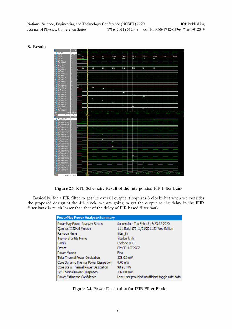
8. Results
Figure 23. RTL Schematic Result of the Interpolated FIR Filter Bank
Basically, for a FIR filter to get the overall output it requires 8 clocks but when we consider
the proposed design at the 4th clock, we are going to get the output so the delay in the IFIR
filter bank is much lesser than that of the delay of FIR based filter bank.
Figure 24. Power Dissipation for IFIR Filter Bank

National Science, Engineering and Technology Conference (NCSET) 2020Journal of Physics: Conference Series 1716 (2021) 012049
IOP Publishingdoi:10.1088/1742-6596/1716/1/012049
17
Figure 25. Delay of IFIR Filter Bank
The Power, Area and Delay in the IFIR filter are 2.05% lesser than that of IIR filter, 70.5% lesser than that of IIR filter and 3.5% less than that of FIR filter respectively. So, the IFIR filter is an apt choice for designing a Filter bank for Digital Hearing Aids.
Table 2. Gates report after RTL Synthesis
Type Instance (cell count) Area (µm2)
Sequential 833 47105.151
Inverter 248 1649.894
Logic 2239 76793.271
Table 3. Areas report after RTL Synthesis
Instance Total cell count Area (µm2)
IFIR Filter Bank 3320 125548.317
After the RTL Synthesis the core of the filter bank has a silicon area of 0.12554mm2 in which 62.48% is Combinational Logic and 37.5% is Sequential Logic. Power consumption of core is 24.28mW @1.8V, 83.33MHz i.e. time period 12ns with 50% duty cycle and timing results are also tabulated in Table 5.
Table 4. Power report after RTL Synthesis
Type of Power Dissipation
(nW)
IFIR Filter bank
Leakage Power 4817.265
Dynamic Power 24282917.901
Total Power 24287735.166

National Science, Engineering and Technology Conference (NCSET) 2020Journal of Physics: Conference Series 1716 (2021) 012049
IOP Publishingdoi:10.1088/1742-6596/1716/1/012049
18
Table 5. Timing report after RTL Synthesis
Instance (ps) IFIR Filter bank
Arrival time 12000
Setup time 418
Required Time 11582
Datapath 9909
Slack 1673
9. Conclusion
The work in this paper explores the use of different types of digital filter designs in the design of digital hearing aids with optimum area, delay and also power consumption. In the preliminary phase different signal processing methodologies were assessed made up of wavelet transform, FIR filter banks, Interpolated FIR filter banks. In the phase two, a software execution was performed on Altera Quartus to check the functionality of the design. In the third phase, everything was in physical design. In physical design power, timing, area are key issues in advanced electronics, which are most essential in the event of hearing aids. In physical design, custom IC design is better to do analysis on power, timing, and area of the design with the help of Cadence-Genus, Innovus. The introduction to IFIR filter gives rise to low delay and in addition gives low delay. Compared with other described filters, the proposed design has an additional advantage of very minimal power consumption for hearing aid. From this research, inference that Non-Uniform Interpolated FIR filter is an appropriate alternative for filter bank design of a hearing aid.
References
[1] Abdul Rehman Buzdar, Azhar Latif, Liguo Sun and Abdullah Buzdar 2016 FPGA prototype
implementation of digital hearing aid from software to complete hardware design, Int.
Journal of Advanced Computer Science and Applications 7(1).pp.645-654.
[2] Ritwik Dhawan and Mahalakshmi P 2016 Digital filtering in hearing aid system for the hearing
impaired Int. Conf. on Electrical, Electronics & Optimization Techniques pp. 1494-1497.
[3] Arpitha Nagesh K, Kavya P, Kavyashree B K, Kruthishree K S, Surekha T P and Girijamba D L
2017 Digital hearing aid for sensorineural hearing loss: (Ski-Slope Hearing Loss) Int. Conf.
on Current Trends in Computer, Electrical, Electronics and Communication.pp.505-507.
[4] Ying Wei and Debao Liu 2013 A reconfigurable digital filter bank for hearing-aid systems with
a variety of sound wave decomposition plans IEEE Trans. Biomed. Eng. 60(6) 1628-1635.
[5] Lunner T and Hellgren J 1991 A digital filter bank hearing aid-design, implementation and
evaluation Int. Conf. on Acoustics, Speech, and Signal Processing.pp.3661-3664.
[6] Vollmer M and Kopmann H 2002 A novel approach to an IIR digital filter bank with
approximately linear phase IEEE Int. Symp. on Circuits and Systems. pp. II-II.
[7] Nielsen L S and Sparso J 1998 Designing asynchronous circuits for low power: an IFIR filter
bank for a digital hearing aid Proc. IEEE 87(2) 268-281.
[8] Lim Y C 1986 A digital filter bank for digital audio systems IEEE Trans. Circuits Syst. CAS-
33, pp.848-849.
[9] Gopal S Gawande and Khanchandani K B 2015 Efficient design and fpga implementation of
digital filter for audio application Int. Conf. on Computing Communication Control and
Automation pp.906-910.
[10] Supriya Dhabal, Lalan Chowdhury S M and Venkateswaran P 2012 A novel low complexity
multichannel cosine modulated filter bank using ifir technique for nearly perfect
reconstruction Int. Conf. on Recent Advances in Information Technology (RAIT).pp.802-

National Science, Engineering and Technology Conference (NCSET) 2020Journal of Physics: Conference Series 1716 (2021) 012049
IOP Publishingdoi:10.1088/1742-6596/1716/1/012049
19
813.
[11] Soon-Suck Jarg, Lingfen Chen, and You-Jung 2005 Digital hearing aid specific µdsp chip by
verilog hdl Proc. Int. Conf. on Control, Automation & Systems.
[12] Damjanovic S, Milic L and Saramaki T 2006 Frequency transformations of iir filters with filter
bank applications IEEE Asia Pacific Conf. on Circuits and Systems pp.1051-1054.
[13] Saab S, Lu W S and Antoniou A 1998 Sequential design of IIR digital filters for low-power
DSP applications IEEE Symp. on Advances in Digital Filtering and Signal Processing.
pp.96-100.
[14] Ying Wei and Debao Liu 2013 A reconfigurable digital filter bank for hearing aid systems with
a variety of sound wave decomposition plans IEEE Trans. Biomed. Eng. 60(6) 1628-1635.
[15] Ying Wei and Yong Lian 2005 A computationally efficient nonuniform FIR digital filter bank
for hearing aids IEEE Transactions on Circuits and Systems 52(12) 2754-2762.
[16] Mehrnia A and Willson A N 2004 On optimal IFIR filter design Proc. of the 2004 International
Symposium on Circuits and Systems. pp. III-133
[17] Nielsen L S and Sparso J 1996 A low-power asynchronous data-path for a FIR filter bank 2nd
Int. Symp. on Advanced Research in Asynchronous Circuits and Systems.pp.268-281
[18] Jorge E Cadena and Louis Beex A A 2016 Interpolated FIR based practically perfect
reconstruction filter bank 50th Asilomar Conf. on Signals, Systems and Computers pp.869-
876.
[19] Ying Wei and Yong Lian 2006 A 16-band nonuniform FIR digital filter bank for hearing aid
IEEE Biomedical Circuits and Systems Conf. pp.186-189
[20] Ying Wei, Tong Ma, Bing Kun Ho and Yong Lian 2019 The design of low-power 16-band
nonuniform filter bank for hearing aids IEEE Trans. Biomed. Circuits Syst. 13(1) 112-123.