Paper No. 12826 · Bitumen-sand mix laid on top of concrete ring wall stops sand from eroding out...
17
Corrosion Risk Assessment, Failure Analysis and Corrosion Mitigation for Aboveground Storage Tanks and Case Histories M. Zee, PhD Matergenics, Inc Fellow of NACE, Fellow of ASM NACE Certified Corrosion/Materials Selection/Design /Coating /Cathodic Protection Specialist Anil Kumar Chikkam, Edward Larkin, Peyman Taheri, Alireza Rezaie, Andrew Campbell Matergenics, Inc 100 Business Center Dr, Pittsburgh, Pennsylvania - 15205 ABSTRACT In this paper a general description of aboveground storage tank (AST) foundations and corrosion mitigation technques to provide long term service is presented. Case studies involving earth foundation, soil corrosion, and double bottom tank are provided. The case studies apply standard electrochemical and failure analysis techniques to determine the primary causes and modes of failures. Soil chemistry, Microbiologically Induced Corrosion (MIC), pH and presence of chlorides in the soil will provide evidence for accelerated corrosion if there is deficiency in cathodic protection. Soil chemistry can be used to predict the pentration due to corrosion attack. If air traps or shielding is present, localized corrosion attack will take place in corrosive soil. Concrete foundations and corrosion inhibitors may be considered in corrosive conditions. Keywords: Corrosion Protection, AST, Vapor Phase Corrosion Inhibitor (VCI), Failure Mechanism, Cathodic Protection, Concrete Foundations, Double Bottom Tanks. 1 Paper No. 12826 ©2019 by NACE International. Requests for permission to publish this manuscript in any form, in part or in whole, must be in writing to NACE International, Publications Division, 15835 Park Ten Place, Houston, Texas 77084. The material presented and the views expressed in this paper are solely those of the author(s) and are not necessarily endorsed by the Association.
Transcript of Paper No. 12826 · Bitumen-sand mix laid on top of concrete ring wall stops sand from eroding out...

Corrosion Risk Assessment, Failure Analysis and Corrosion Mitigation
for Aboveground Storage Tanks and Case Histories
M. Zee, PhD Matergenics, Inc
Fellow of NACE, Fellow of ASM NACE Certified Corrosion/Materials Selection/Design
/Coating /Cathodic Protection Specialist
Anil Kumar Chikkam, Edward Larkin, Peyman Taheri, Alireza Rezaie, Andrew Campbell Matergenics, Inc
100 Business Center Dr, Pittsburgh, Pennsylvania - 15205
ABSTRACT
In this paper a general description of aboveground storage tank (AST) foundations and corrosion
mitigation technques to provide long term service is presented. Case studies involving earth
foundation, soil corrosion, and double bottom tank are provided. The case studies apply standard
electrochemical and failure analysis techniques to determine the primary causes and modes of failures.
Soil chemistry, Microbiologically Induced Corrosion (MIC), pH and presence of chlorides in the soil will
provide evidence for accelerated corrosion if there is deficiency in cathodic protection. Soil chemistry
can be used to predict the pentration due to corrosion attack. If air traps or shielding is present,
localized corrosion attack will take place in corrosive soil. Concrete foundations and corrosion inhibitors
may be considered in corrosive conditions.
Keywords: Corrosion Protection, AST, Vapor Phase Corrosion Inhibitor (VCI), Failure Mechanism,
Cathodic Protection, Concrete Foundations, Double Bottom Tanks.
1
Paper No.
12826
©2019 by NACE International.Requests for permission to publish this manuscript in any form, in part or in whole, must be in writing toNACE International, Publications Division, 15835 Park Ten Place, Houston, Texas 77084.The material presented and the views expressed in this paper are solely those of the author(s) and are not necessarily endorsed by the Association.

INTRODUCTION Unless protective measures are taken, ungrade steel storage tanks, piping, and other metallic
components of fuel storage systems corrode and leak product into the environment. Corrosion can
attack the metal either over the entire surface of the metal (general corrosion) or in a small, localized
area, creating a hole. Localized corrosion can perforate an unprotected tank in little as a few years and
is the most common form of corrosion.
Tank bottom corrosion from the soil could be prevented by using a concrete foundation but corrosion
could still occur due to moisture accumulation between the tank bottom and the concrete pad due to
condensation, blowing rain or snow, or flooding due to inadequate drainage and moisture entrapment.
Proper measures should be taken for concrete foundation construction to eliminate the ingress of water
and other corrosive contaminants between the tank bottom and the concrete pad.
A typical system for Monitoring and Mitigation of Corrosion in the Interstitial Space includes a) sealing
any gaps between the tank floor and dead shell on double-bottom tanks, or gaps between the tank floor
and concrete ring wall on single bottom tanks to prevent intrusion of fresh water and air into the
interstitial spaces of these tank systems, b) engineered application of the Vapor Phase Corrosion
Inhibitors (VCI) into the interstitial space in such a way that effective distribution of the chemistry is
ensured and c) a corrosion rate monitoring system utilizing electrical resistance probe technology to
measure the real-time rate of corrosion shoud be placed within the interstitial space and near the tank
floor.
TYPES OF FOUNDATIONS FOR AST
EARTH FOUNDATION Earth foundation is the most often applied foundation as it is easy to construct and also it is the
cheapest compared to other foundations.However, the challenges with earth foundation are: 1) small
leak moving out of the soil could lead to the destruction of the tank, 2) poor leveling or drainage of the
bottom of the tank, 3) ineffective corrosion protection of the tank bottom due to voids and water pooling
owing to uneven settlement of the foundation.
In practice, earth foundation will be used when the soil can withstand the pressure of the upper steel
construction. Prior to earth foundation, determining the aggressive ions such as chlorides and sulfates
along with measuring the pH and resistivity of the soil is very important as the soil analysis results will
aid in designing the most practical corrosion prevention system for the tank bottom. In order to avoid
corrosion of AST bottom due to corrosive soils, clean sand is used beneath the AST bottom.
EARTH FOUNDATION WITH A CONCRETE RING WALL This particular foundation is most widely used for large diameter aboveground storage tanks because
rigid reinforced concrete ring provides stability to the larger diameter tanks. It provides better leveling
compared to earth foundation. However, the major drawback of this foundation is irregular settlement of
the foundation/backfill that could lead to voids in the soil to steel interface.
2
©2019 by NACE International.Requests for permission to publish this manuscript in any form, in part or in whole, must be in writing toNACE International, Publications Division, 15835 Park Ten Place, Houston, Texas 77084.The material presented and the views expressed in this paper are solely those of the author(s) and are not necessarily endorsed by the Association.

Clean sand is the most common material used for backfill beneath the AST bottom. Clean sand
minimum of 75 mm (3 in) thick is laid on top of the foundation. It is recommended to place 150 mm (6
in) thick of clean sand if cathodic protection is to be utilized. Bitumen-sand (cold patch asphalt) mix 50
mm (2 in) thick laid on top of the foundation under the tank steel bottom acts as a corrosion prevention
layer. Bitumen-sand mix laid on top of concrete ring wall stops sand from eroding out from under the
tank. This type of foundation allows for cathodic protection and leak detection materials/components to
be placed in, or pass through, the sand pad for corrosion prevention and monitoring.
EARTH FOUNDATION WITH CRUSHED STONE RING WALL This particular foundation is considered when high loads are imposed by a shell on the foundation.The
advantages of this foundation is 1) good leveling, 2) preserves contour during construction and, 3)
retains fill under the tank bottom. The drawback of this foundation is the difficulty of construction to
close tolerances, selection of design and pitting corrosion of the AST bottom at contact areas between
the large particles of the tank pad and the metal due to formation of differential aeration corrosion cells.
In the event of water intrusion in to the tank bottom, the environment under the tank becomes alkaline,
which may reduce corrosion. However, with time infiltrate the pad, corrosion may accelerate. Thus, the
use of crushed limestone or clam shells does not clearly eliminate the need for cathodic protection.1
This type of foundation allows for Cathodic protection and leak detection materials/components to be
placed in, or pass through, the sand pad for corrosion prevention and monitoring. The use of cathodic
protection on this type of foundation has produced mixed result.
With aging, there is a possibility that all the abovementioned foundations provide limited degree of
protection due to ingress of corrosive ions from soil such as moisture, chlorides, and microorganisms.
Many tanks are upgraded with double bottoms with interstitial space CP systems. However, designing
and the maintenance/repair of CP system is problematic and considerations should be given to
corrosion monitoring under the tank to monitor the effectiveness of corrosion mitigation.
SOIL CORROSIVITY
Soil resistivity may provide valuable information about the corrosivity of the material used in the
interstitial spaces, under and around a tank. A general resistivity classification is given in Table 1.
Table 1
Classification of Soil Corrosivity Based on Resistivity 2
Resistivity Range (ohm-cm) Corrosivity
0 - 1000 Very severe
1,001 – 2,000 Severe
2,001 – 5,000 Moderate
5,001 – 10,000 Mild
>10,000 Very mild
There are several techniques for measuring soil resistivity. A common method is described in ASTM (1)
G57.3 It should be noted that soil resistivity alone should not be used to determine soil corrosivity. The
(1) ASTM International, 100 Barr Harbor Dr., West Conshohocken, PA
3
©2019 by NACE International.Requests for permission to publish this manuscript in any form, in part or in whole, must be in writing toNACE International, Publications Division, 15835 Park Ten Place, Houston, Texas 77084.The material presented and the views expressed in this paper are solely those of the author(s) and are not necessarily endorsed by the Association.

resistivity of the pad material may be higher than the existing surrounding soil. Corrosive soil beneath
the higher resistivity pad material may contaminate the pad fill by capillary action and should be a
consideration when determining sand pad thickness. Thus, resistivity of surrounding soil may be used
to help determine the probability of corrosion on the tank bottom. The results of soil resistivity surveys
should be considered and used to help determine the need for cathodic protection. However, other
properties such as chlorides, sulfides and sulfates of the soil should also be considered. Example of
analysis for sand in an AST application s shown in Table 2.
Table 2
Sand analysis results
Parameter & Method Test Result API 2 651 4
Guideline Limit
Comments
Resistivity FM 5-551 57,400 ohm-cm
(dry)
>30,000 ohm-cm Pass
18,240 ohm-cm
(saturated)
Lower when wet due to
chlorides (salt entrainment)
Water content
ASTM D2216
5.9% <5% Marginal Fail – suggest
scheduling use in dry season
pH FM 5-550 8.01 6.5 - 8.5 Pass
Chloride FM 5-552 15 mg/L <300 mg/L Pass
Sulphate FM 5-553 7 mg/L <1000 mg/L Pass
Figure 1: Photograph showing three different corrosivity rating and resulting pentration rates that can be used for remaining life determination.
(2) American Petroleum Institute (API), 1220 L Street, NW, Washington, DC 20005-4070, USA
4
©2019 by NACE International.Requests for permission to publish this manuscript in any form, in part or in whole, must be in writing toNACE International, Publications Division, 15835 Park Ten Place, Houston, Texas 77084.The material presented and the views expressed in this paper are solely those of the author(s) and are not necessarily endorsed by the Association.

PREDICTIVE MODELING AND SOIL CORROSIVITY DETERMINATION A mathematical model to estimate the localized corrosion penetration and propagation in buried
structures has been developed considering soil chemistry in the field (pH, resistivity, redox potential,
and electrochemical potential at the soil–metallic structure interface) under the tank. According to many
test results, this model provides an adequate description of thickness loss due to corrosion attack.
This type of predictive modeling provides good damage prediction by using soil corrosivity parameters
typically measurable in field. The plots (Figure 1) provide three different corrosivity rating and resulting
pentration rates that can be used for remaining life determination.
FOUNDATION CORROSION CONTROL For a better outcome, the following corrosion controls can be used a standalone or in combination.
CATHODIC PROTECTION Cathodic protection to the tank bottom plates can be provided by either sacrificial galvanic anodes or by
an impressed current cathodic protection (ICCP) system. Galvanic system is normally considered only
for small diameter tanks (<20 feet (6.10 m)) or for the tanks with externally coated bottoms. Cathodic
protection systems are designed and installed to prevent corrosion of a tank bottom by satisfying the
requirements of one or more of the NACE criteria stated below.5
A negative (cathodic) potential of at least 850 mV with the CP applied. This potential is
measured with respect to a saturated copper/copper sulfate reference electrode contacting the
electrolyte. Voltage drops other than those across the structure/electrolyte boundary must be
considered for valid interpretation of this potential measurement.
A negative polarized potential of at least 850 mV relative to a saturated copper/copper sulfate
reference electrode, abbreviated as CSE).
A minimum of 100 mV of cathodic polarization. The formation or decay of polarization may be
used to satisfy this criterion.
In order to achieve the desired results, a cathodic protection system shall be properly designed. The
cathodic protection system should be designed after a study of the following items:
design and engineering specifications and practices
operating procedures;
safety, environmental, and hazardous area requirements;
Field testing.
Cathodic protection is achieved by directing the flow of current from an anode to a cathode, resulting in
protection of the cathode. Anything that acts as a barrier or shield to the flow of current will prevent the
application of cathodic protection. In 2012, a survey carried out at an oil and gas facility in the Arabian
Peninsula on randomly selected tanks showed that soil-side corrosion was present on all CP protected
and non-CP protected tanks.6 Voids or air gaps formed between the tank bottom plates and the tank
foundation due to filling and refilling of the storage tanks and weld overlaps also prevent the CP current
from reaching to the bottom plates at these areas.
5
©2019 by NACE International.Requests for permission to publish this manuscript in any form, in part or in whole, must be in writing toNACE International, Publications Division, 15835 Park Ten Place, Houston, Texas 77084.The material presented and the views expressed in this paper are solely those of the author(s) and are not necessarily endorsed by the Association.

COATING To avoid soil-side corrosion of the tank bottoms, coatings may be considered in conjunction with
cathodic protection. However, mechanical damages during installation, pin holes, blisters and
delamination in the coatings are real challenges. Damaged coating substantially reduce CP current
requirement and enhance CP current distribution unless shielding conditions exists for CP at the
coating defect/crevice.
VAPOR PHASE INHIBITOR (VCI) VCI is a chemical substance when injected into the interstitial spaces between the foundation and the
tank bottom adsorps onto surfaces in the space and prevents or decreases the reaction of the tank
bottom with the environment. VCI chemistry is also available as a thin liquid solution that can be
delivered into the interstitial spaces under the tank floor through injection pipes placed in the sand layer
while the tank is in service.7
Research and fieldwork show that some vapor phase corrosion inhibitors (VCI) by themselves or in
combination with cathodic protection can be used for the protection of the bottoms of the above ground
storage tanks. 8,9,10
CORROSION MONITORING Monitoring the corrosive environment of the tank bottom is important in determining predictive
maintenance plans to increase the service life of the tank. Tank-to-soil potential measurement is the
standard method of determining the effectiveness of cathodic protection at the tank bottom. These
measurements are performed using a high-impedance voltmeter and a reference electrode contacting
the electrolyte (sand in between both tank bottoms) in the dual bottom storage tanks.
Another good resource in determining the corrosion rate of the underside of the tank is electrical
resistance (ER) probes. ER probe measures electrical resistance of a steel element in the probe face
over a period of time. The increase in electrical resistance compared to initial reads is an indication of
accumulated corrosion in the exposure period. ER probes can be used in a wide range of environments
and can be considered for low conductivity and nonaqueous conditions, where electrochemical
techniques are generally unsuitable. ER corrosion sensors have been likened to "intelligent" coupons,
facilitating a simple corrosion measurement without the need to remove the coupon from service.
LEAK DETECTION
Leak detection is an effective way to minimize environmental damage and limiting the cost for cleanup.
There are few different methods for leak detection but the most common are:
1. Secondary containment with interstistial monitoring: Secondary containment uses a barrier or a
liner around the tank. The product leaked from the tank is directed towards an interstitial
monitor located between the tank and the outer barrier. Interstitial monitoring methods include
the use of an automated vapor or liquid sensor permanently installed in the system to monitor
interstitial spaces.
2. Automatic tank gauging system: In this system the probe installed in the tank is connected to a
monitor to provide information on product level and temperature. The system automatically
calculates the change in product volume that can indicate a leaking tank.
6
©2019 by NACE International.Requests for permission to publish this manuscript in any form, in part or in whole, must be in writing toNACE International, Publications Division, 15835 Park Ten Place, Houston, Texas 77084.The material presented and the views expressed in this paper are solely those of the author(s) and are not necessarily endorsed by the Association.

3. Vapor monitoring: Product fumes in the soil around the tank or special tracer chemicals added
to the tank which escape in order to check for a leak can be measured by vapor monitoring.
This method requires installation monitoring wells at strategic locations. Vapor monitoring
should be performed periodically using permanently installed equipment.
4. Groundwater monitoring: Liquid floating on the ground water can be sensed by groundwater
monitoring. In this monitoring method, monitoring wells will be installed in the ground near the
tank and along the piping. The wells should be checked periodically with permanently installed
equipment to discover if leaked product has reached groundwater. It is recommended that this
method should not be used at the site locations where groundwater is more than 20 feet (6.10
m) below the surface.
This systems are best when used in conjunction with one another with a proper maintainance schedule.
Electrochemical measurements and installing test copuns are necessary to determine that corrosion
protection has been established. Conditions that affect protection are subject to change with time, this
requires periodic measurements and inspections to determine that corrosion protection is still being
achieved.
CASE HISTORY 1
This section describes the investigation of a corrosion failure and perforation of the bottom plate on an
aboveground diesel fuel storage tank in an island environment. 60 feet (18.29 m) diameter tank was
constructed on concrete ringwall in 2004. The nominal bottom plate thickness is 0.312 inch (0.12 cm).
As part of the investigation an (1) on-site inspection, (2) cathodic protection system evaluation, (3) soil
corrosivity study and metallurgical failure analysis was performed. These efforts are described in the
following sections. Seven (7) of these areas were through-thickness holes initiating from soil side. 160
areas were exhibiting accelerated thickness loss on the soil side.
The onsite investigation consisted of internal inspection, visual examination of bottom plate,
electrochemical potential and rectifier readings and samples were identified for subsequent laboratory
testing.
Tank considered for inspection is shown in Figure 2. Tank internal photographs are shown in Figures 3
and 4. There is extensive thickness loss and perforation observed on bottom plate.
ON-SITE CATHODIC PROTECTION EVALUATION The cathodic protection system was installed during construction of the tank. The cathodic protection
system consists of an impressed current cathodic protection (ICCP) system with a rectifier and four
mixed metal oxide (MMO) anode hoops placed under the bottom plate. Commissioning of the cathodic
protection system was performed on August 1, 2005.
A measurement of 1.8 Amps was obtained across the shunts in the junction box at the time of the
investigation. The potentials collected at the junction box between the cables from tank and
permanenet reference electrodes are in the range -419mVCSE to – 437mVCSE which indicates less than
adequate protection. 100mV shift criteria is also not satisfied. The presence of extensive loss in
thickness, perforation and review of historic data also indicates a lack of corrosion control for the
bottom plate.
7
©2019 by NACE International.Requests for permission to publish this manuscript in any form, in part or in whole, must be in writing toNACE International, Publications Division, 15835 Park Ten Place, Houston, Texas 77084.The material presented and the views expressed in this paper are solely those of the author(s) and are not necessarily endorsed by the Association.

LABORATORY INVESTIGATION A laboratory investigation was performed that consisted of a soil corrosivity study and metallurgical
failure analysis of the corroded section of the tank.
SOIL CORROSIVITY STUDY Analysis of soil sample collected from the perforated area revealed that the soil resistivity was 1300
ohm-cm. This indicates a conductive soil which is considered corrosive in direct exposure to steel with
mill scale. Corrosion rate data was measured using Linear Polarization Resistance (LPR). Corrosion
rate of 3.8 mpy was measured for water saturated soil sample collected from project site. Soil chemistry
indicated the presence of calcium carbonate, iron corrosion products and silicates.
FAILURE ANALYSIS
VISUAL EXAMINATION The underside of the sample taken from tank bottom plate is shown in Figure 5. Note that the second,
circular hole in the center of the sample diameter is a drilled hole needed for sample removal. Thick
corrosion products and deposits were observed on one area of the bottom plate underside. Loss of
plate thickness due to corrosion was also observed in some areas including around the hole. Figure 6
shows the locations of maximum corrosion product thickness, and loss of thickness due to corrosion
with respect to the hole. The line in Figure 5 shows the plane of cutting and cross section examination.
The hole in the tank bottom as viewed from the outside of the tank is shown in Figure 7. The hole in the
tank bottom as viewed from the inside of the tank is shown in Figures 8. No appreciable corrosion was
observed on the inside surface of the tank bottom plate.
The corrosion products on the underside of the tank bottom plate were examined at moderate
magnifications using an optical stereomicroscope. The corrosion products are shown in Figures 9 - 10.
SEM/EDS ANALYSIS Qualitative analysis of the corrosion products on the underside of the tank bottom plate was determined
using a scanning electron microscope (SEM) equipped with an energy dispersive x-ray spectrometer
(EDS). A spectrum of the bright orange corrosion products is shown in Figure 11 and consisted
primarily of iron (Fe) and oxygen (O) plus lesser amounts of carbon and chlorine (Cl). A spectrum of the
black corrosion products is shown in Figure 12 and consisted primarily of iron (Fe) and oxygen (O) plus
lesser amounts of aluminum (Al), silicon (Si), sulfur (S), chlorine (Cl), calcium (Ca), chromium (Cr),
manganese (Mn) and copper (Cu).
METALLOGRAPHIC EXAMINATION Transverse cross sections through an area of minimal plate thickness loss, maximum plate thickness
loss, and maximum corrosion product thickness were prepared for subsequent metallographic
examination. In the as polished condition the corrosion in a lightly corroded area of the tank bottom
underside is shown in Figures 13 and 14. A layer of mill scale was observed within the corrosion
products that had been lifted by corrosion occurring underneath the mill scale layer (Figure 15). The
thick corrosion product layer is shown in Figure 16.
8
©2019 by NACE International.Requests for permission to publish this manuscript in any form, in part or in whole, must be in writing toNACE International, Publications Division, 15835 Park Ten Place, Houston, Texas 77084.The material presented and the views expressed in this paper are solely those of the author(s) and are not necessarily endorsed by the Association.

SUMMARY OF FINDINGS Tank failed due to accelerated corrosion of the bottom plate side exposed to the soil. Extensive
thickness loss and 7 perforated holes were observed during the inspection of the tank. The existing
cathodic protection system did not protect these areas. The presence of extensive thickness loss at the
bottom plate, perforation, through thickness holes due to corrosion attack and review of historic data
indicates the CP system was not adequate and failed to provide corrosion protection and extend the life
of the tank adequately.
CASE HISTORY 2
This section describes the corrosion risk assessment of a double bottom aboveground storage tank. As
part of the investigation an (1) on-site inspection, (2) cathodic protection system evaluation, (3) soil
corrosivity study and metallurgical failure analysis was performed. These efforts are described in the
following sections. 50 feet (15.24m) diameter tank was constructed on concrete ringwall in 1957. New
second bottom was put in 1993. The nominal bottom plate thickness is 0.250 inch (0.1 cm). Galvanic
anode cathodic protection system was installed during construction of the tank.
ON-SITE TESTING
POTENTIAL MEASUREMENT
In-situ potential measurements was performed by placing a copper/copper sulphate (CuSO4) reference
electrode in the electrolyte (sand between tank bottoms) and electrically connecting a high impedance
potential measuring instrument, high impedance voltmeter, between the reference electrode and the
top tank bottom (Figure 17). Potential measurements revealed that at least -850 mV instant OFF and
100 mV shift NACE CP criteria are not satisfied which indicates that there is no cathodic protection for
the tanks.
CURRENT REQUIREMENT TEST
Current requirement test was performed to identify the number of anodes to be placed between the
tank bottoms in order to establish cathodic protection of the tank bottoms. During this test, 15 feet (4.57
m) long randomly perforated PVC pipe was inserted in between the tank bottoms and then 15 feet
(4.57 m) long carbon steel rod was inserted inside the PVC pipe. PVC pipe was used to avoid the
contact between carbon steel rod and the tank bottoms. In this case, carbon steel rod is the auxiliary
electrode (Figure 18).
External power source is connected to the auxiliary electrode and the current is increased in steps up to
10 amperes. Reference electrode is placed in other ports for the potential measurements. Even with
increase in current settings to the maximum in the external power source unit, there was no increase in
potential reads (Figure 19) which indicates low conductivity of the electrolyte and that large amount of
current is required to achieve -850mV minimum NACE CP criteria.
The findings of the site visit are as follows:
1. During CP assessment, it was noticed that at most of the locations the sand was not in contact with
the top bottom plate. At the time of testing, tank was full. It should be noted that CP will be
9
©2019 by NACE International.Requests for permission to publish this manuscript in any form, in part or in whole, must be in writing toNACE International, Publications Division, 15835 Park Ten Place, Houston, Texas 77084.The material presented and the views expressed in this paper are solely those of the author(s) and are not necessarily endorsed by the Association.
ineffective at the locations where the sand is not in contact with the bottom plate and accelerated
corrosion could take place at these locations.
2. From the CP survey, it was observed that a large bare surface has to be protected. So, large
amount of current is required to protect the large bare surface of the tank bottom.
3. As the area around the tank is lined, the anodes should be placed in between the two bottom
plates.
4. Since a large amount of current is required to protect the large bare surface of the tank bottom,
several anodes have to be installed in between the two bottom plates. Careful attention has to be
paid to avoid placing of the anodes too close to each other and to the tank bottoms. If the anodes
are in close proximity to one another, there is a possible threat of hydrogen generation when CP is
in place which could result in unacceptable risk of hydrogen gas ignitions. Hydrogen generation
depends on pH, oxygen concentration and presence of magnetite on the bottom surface .
Hydrogen generation should be considered and is considered a risk at less noble potentials in this
application.
SOIL RESISTIVITY MEASUREMENT
Field measurements involved the use of four metallic pins driven into the ground outside the
containment dike. The instrument supplies a current to the soil through two outer pin electrodes and the
voltage difference is read between the two inner pin electrodes. To measure the soil resistivity at
different depths, measurements were performed with different spacing (10, 15 and 20 feet) between the
pins at the surface. Test results indicate that the soil is non-corrosive.
Table 3
Soil Resistivity Test results
Depth, ft Resistance, ohms Resistivity, ohms-cm
10 5.4 10341
15 3.5 10054
20 2.1 8043
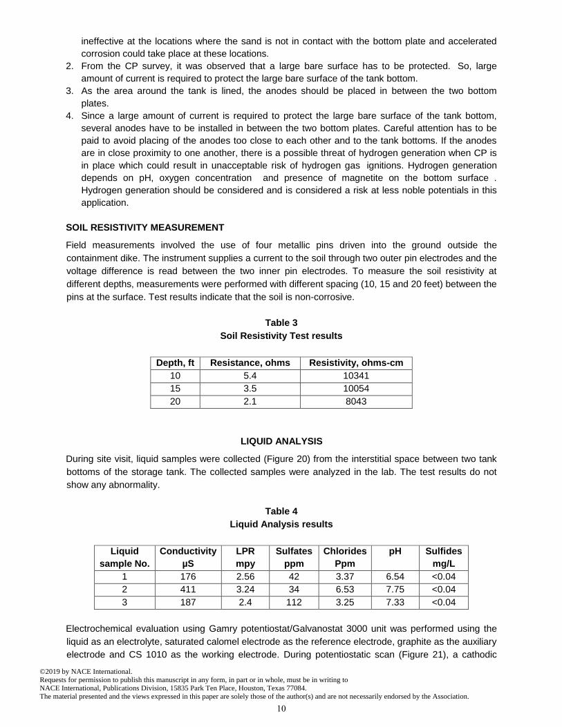
LIQUID ANALYSIS
During site visit, liquid samples were collected (Figure 20) from the interstitial space between two tank
bottoms of the storage tank. The collected samples were analyzed in the lab. The test results do not
show any abnormality.
Table 4
Liquid Analysis results
Liquid
sample No.
Conductivity
µS
LPR
mpy
Sulfates
ppm
Chlorides
Ppm
pH Sulfides
mg/L
1 176 2.56 42 3.37 6.54 <0.04
2 411 3.24 34 6.53 7.75 <0.04
3 187 2.4 112 3.25 7.33 <0.04
Electrochemical evaluation using Gamry potentiostat/Galvanostat 3000 unit was performed using the
liquid as an electrolyte, saturated calomel electrode as the reference electrode, graphite as the auxiliary
electrode and CS 1010 as the working electrode. During potentiostatic scan (Figure 21), a cathodic
10
©2019 by NACE International.Requests for permission to publish this manuscript in any form, in part or in whole, must be in writing toNACE International, Publications Division, 15835 Park Ten Place, Houston, Texas 77084.The material presented and the views expressed in this paper are solely those of the author(s) and are not necessarily endorsed by the Association.

potential of -1.022VCSE was applied to the working electrode and the current corressponsing to this
potential was measured as 160 microamps for the exposed working electrode area of 8.3 cm2 (1.29
inch2).
ANALYSIS OF SAND
During site visit, sand sample was also collected from the interstitial space between two tank bottoms of
the storage tank. The collected sand sample was analyzed in the lab. The test results are shown in
Table 5. Moreover, corrosion rate was also predicted (Figure 22).
Table 5
Sand Analysis results
As
Received
Resistivity
Ω-cm
LPR
mpy
Sulfates
ppm
Chlorides
ppm
pH Moisture
%
Redox
mV
Sulfides
mg/L
1,394 2.79 10 2.01 8.64 20 291.9 <0.04
SUMMARY OF FINDINGS
Considering the challenges with installation of anodes in between the tank bottoms, consideration of
the injection of VCI/contact inhibitor between the tank bottom plates is recommended. A promising
industrial practice is to introduce VCI materials under tank bottoms to either supplement existing CP
systems or provide protection in its absence.
RECOMMENDATIONS
Different types of foundations are considered for aboveground storage tanks based on the surface,
subsurface, and climatic conditions. The pad material, air gap and voids under the tank has a
significant influence on the soil-side corrosion of the tank bottom and can influence the effectiveness
and applicability of external cathodic protection. Moisture and presence of salty environments (C5)
should be considered in corrosion mitigation strategy.
Reference electrodes and ER probes should be installed at various locations under the tank for
monitoring the corrosion rate to determine the remaining life of the VCI.
Reference cells should be installed under the tank. The investment is worth as we can achieve
accurate potential readings by installing reference electrodes under the tank.
ER probes need to be monitored on a monthly basis to ensure corrosion protection.
The chim of the tank should be sealed to prevent intrusion of moisture.
For optimal corrosion protection utilizing the ring wall foundation, cathodic protection should be used.
An impressed grid system utilizing mixed metal oxide ribbon anodes (MMO) coke breeze and VCI
should be installed under the tank with an HDPE linear as a bearer in case of leaks and to prevent
shallow ground water from migrating to the sand causing a highly corrosive environment.
Cathodic protection should be designed for the life of the tank bottom.
Reference cells should be placed under the tank.
11
©2019 by NACE International.Requests for permission to publish this manuscript in any form, in part or in whole, must be in writing toNACE International, Publications Division, 15835 Park Ten Place, Houston, Texas 77084.The material presented and the views expressed in this paper are solely those of the author(s) and are not necessarily endorsed by the Association.

VCI in conjunction with cathodic protection can last up to 15 years depending on the
corrosiveness of the environment.11
ER probes need to be monitored on a yearly basis to ensure corrosion protection.
Cathodic protection needs to be monitored on a yearly basis to ensure that criteria is met.
The rectifier needs to be monitored on a bi-monthly basis.
The chim of the tank should be sealed to prevent intrusion of moisture.
Corrosion protection can be achieved, provided care is taken in montoring and quantifing the corrosion
risk.
REFERENCES
1. API 650 (latest revision), “Welded Tanks for Oil Storage” (1220 L Street, NW, Washington, DC 20005-4070, USA).
2. J. D. Palmer Mater. Perform., 13(1), 41 – 46. 3. ASTM G57 (latest revision), “Standard Test Method for Field Measurement of Soil Resistivity Using
the Wenner Four-Electrode Method,” (West Conshohocken, PA: ASTM). 4. API 651 (latest revision), “Cathodic Protection of Aboveground Petroleum Storage Tanks” (1220 L
Street, NW, Washington, DC 20005-4070, USA). 5. NACE SP0285 (formerly RP0285) (latest revision), “External Corrosion Control of Underground
Storage Tank Systems by Cathodic Protection” (Houston, TX: NACE). 6. I.Y. Barnawi, “Comparison of corrosion attack on tank bottoms with and without cathodic
protection” MP (8) (2012), 31-35. 7. T. Whited, “Mitigation of Soil side corrosion on double contained aboveground storage tank floors”,
MP (2011), 7-10. 8. X. Yu, “Evaluation of the Tank Bottom Corrosion and CP Effectiveness at a Saudi Aramco Crude
Oil Tank Farm,” Paper No. 10043, 13th Middle East Corrosion Conference, Bahrain (2010). 9. T. Whited, X. Yu, R. Tems, “Mitigating Soil-Side Corrosion on Crude Oil Tank Bottoms Using Vapor-
phase Corrosion Inhibitors”, CORROSION 2013, Paper No. 2242, (Houston, TX, NACE, 2013). 10. Calvin R. Pynn, Khalil Abed, “Compatibility and Interactions Between Cathodic Protection and a
Vapor Phase Corrosion Inhibitor”, MP (2017),14-18. 11. A. Gandhi, “Storage Tank Bottom Protection Using Vapor-phase Corrosion Inhibitors”, MP (2001),
28-30.
Figure 2: Photograph showing Fuel storage tanks.
12
©2019 by NACE International.Requests for permission to publish this manuscript in any form, in part or in whole, must be in writing toNACE International, Publications Division, 15835 Park Ten Place, Houston, Texas 77084.The material presented and the views expressed in this paper are solely those of the author(s) and are not necessarily endorsed by the Association.

Figure 3: Photograph exhibiting perforated areas due to external corrosion. Perforated
areas are randomly distributed.
Figure 4: Close up of a perforated area
Figure 5: Photograph showing the hole in the tank bottom as viewed from the outside of the
tank. Note-circular hole in center is a drilled hole.
Figure 6: Photograph shows the locations of maximum corrosion product thickness and
loss of thickness due to corrosion.
Figure 7: Photograph showing the hole in the tank bottom as viewed from the outside of the
tank.
13
©2019 by NACE International.Requests for permission to publish this manuscript in any form, in part or in whole, must be in writing toNACE International, Publications Division, 15835 Park Ten Place, Houston, Texas 77084.The material presented and the views expressed in this paper are solely those of the author(s) and are not necessarily endorsed by the Association.

Figure 8: Photograph showing the hole in the tank bottom as viewed from the inside of the tank.
Note-circular hole in center is a drilled hole.
Figure 9: Photograph at 7x showing the
corrosion products on the underside of the tank bottom.
Figure 10: Photograph at 7x showing the corrosion products on the underside of the tank
bottom.
Figure 11: EDS spectrum of the bright orange
corrosion products. Figure 12: EDS spectrum of the black corrosion
products.
Note the presence of chlorides and sulfur containing compounds.
14
©2019 by NACE International.Requests for permission to publish this manuscript in any form, in part or in whole, must be in writing toNACE International, Publications Division, 15835 Park Ten Place, Houston, Texas 77084.The material presented and the views expressed in this paper are solely those of the author(s) and are not necessarily endorsed by the Association.

Figure 13: Photograph at 50x showing
corrosion of the underside of the tank bottom in an area on minimal corrosion. As polished.
Figure 14: Photograph at 50x showing corrosion of the underside of the tank bottom in
an area on minimal corrosion. As polished.
Figure 15: Photograph at 200x showing mill scale
within the corrosion products. As polished. Figure 16: Photograph at 50x showing the thick corrosion products on the underside of the tank
bottom. As polished.
Figure 17: Photograph showing that reference electrode is pushed into the sand from the slot available between both tank bottoms and the tank bottom – to – sand potential was measured.
Reference
Electrode
15
©2019 by NACE International.Requests for permission to publish this manuscript in any form, in part or in whole, must be in writing toNACE International, Publications Division, 15835 Park Ten Place, Houston, Texas 77084.The material presented and the views expressed in this paper are solely those of the author(s) and are not necessarily endorsed by the Association.

Figure 18: Photograph showing placing of auxiliary electrode in between the tank bottoms.
Figure 19: Photograph showing that at least -850 mV with the CP applied criteria is not satisfied which
indicates that there is no cathodic protection for the tanks. Reference electrode is pushed into the sand from the slot available between both tank bottoms
16
©2019 by NACE International.Requests for permission to publish this manuscript in any form, in part or in whole, must be in writing toNACE International, Publications Division, 15835 Park Ten Place, Houston, Texas 77084.The material presented and the views expressed in this paper are solely those of the author(s) and are not necessarily endorsed by the Association.

Figure 20: Photograph showing collection of liquid samples from the space between the tank
bottoms of the storage tank.
Figure 21: Photograph showing potentiostatic scan plot
Figure 22: Photograph showing resulting pentration rates that can be used for remaining life determination.
17
©2019 by NACE International.Requests for permission to publish this manuscript in any form, in part or in whole, must be in writing toNACE International, Publications Division, 15835 Park Ten Place, Houston, Texas 77084.The material presented and the views expressed in this paper are solely those of the author(s) and are not necessarily endorsed by the Association.