paper. - International Energy...
71
Collection of the Position Paper and all final deliverable papers of the joint task IEA SHC Task 42 and IEA ECES Annex 29. The papers were presented at the SHC Conference 2015, December 2-4 Istanbul, Turkey. They will be published in the proceedings of this conference in due time. Contents: 1. Position Paper Matthias Rommel and Wim van Helden 2 2. Overview on the Task Compact Thermal Energy Storage Matthias Rommel, Wim van Helden, Andreas Hauer 12 3. WG_A1: Engineering and processing of PDMs, TCMs and sorption materials Alenka Ristic et al. 17 4. WG_A2: Standardization of PCM characterization via DSC Stefan Gschwander et al. 28 5. WG_A3: Advanced numerical modelling techniques to tune the properties of heat storage materials for optimal reactor performance S.V. Gaaastra-Nedea, C.C.M. Rindt et al. 34 6. WG_B: Applications of Compact Thermal Energy Storage Wim van Helden, Motoi Yamaha et al. 45 7. WG_C: A simple tool for the economic evaluation of thermal energy storages Christoph Rathgeber et al. 62 M. Rommel, 22 March 2016
Transcript of paper. - International Energy...

Collection of the Position Paper and all final deliverable papers of the joint task IEA SHC Task 42 and IEA ECES Annex 29. The papers were presented at the SHC Conference 2015, December 2-4 Istanbul, Turkey. They will be published in the proceedings of this conference in due time. Contents: 1. Position Paper Matthias Rommel and Wim van Helden 2 2. Overview on the Task Compact Thermal Energy Storage Matthias Rommel, Wim van Helden, Andreas Hauer 12 3. WG_A1: Engineering and processing of PDMs, TCMs and sorption materials Alenka Ristic et al. 17 4. WG_A2: Standardization of PCM characterization via DSC Stefan Gschwander et al. 28 5. WG_A3: Advanced numerical modelling techniques to tune the properties of heat storage materials for optimal reactor performance S.V. Gaaastra-Nedea, C.C.M. Rindt et al. 34 6. WG_B: Applications of Compact Thermal Energy Storage Wim van Helden, Motoi Yamaha et al. 45 7. WG_C: A simple tool for the economic evaluation of thermal energy storages Christoph Rathgeber et al. 62
M. Rommel, 22 March 2016

Task 42 (ECES Annex 29)
Compact Thermal Energy Storage: Material Development for System Integration
Compact Thermal Energy Storage IEA SHC Position Paper August 2015
2

SHC Task 42 (ECES Annex 29) – Compact Thermal Energy Storage August 2015 SHC Position Paper Page 2 / 10
Contents Aim of the Position Paper ................................................................. 3
Executive Summary .......................................................................... 3
Introduction and Relevance ............................................................. 4
Status of the Technology ................................................................. 6
Potential ............................................................................................ 6
Current Barriers ................................................................................ 7
Actions Needed ................................................................................ 9
Acknowledgement .......................................................................... 10
This document was prepared by Wim van Helden and Matthias Rommel Co-Operating Agents of Task 42: Compact Thermal Energy Storage: Material Development for System Integration of the IEA Solar Heating & Cooling Programme.
© IEA Solar Heating and Cooling Programme
3

SHC Task 42 (ECES Annex 29) – Compact Thermal Energy Storage August 2015 SHC Position Paper Page 3 / 10
Compact Thermal Energy Storage – Position Paper
Aim of the Position Paper This position paper explains the potential, the present status of development and the market status of compact thermal energy storages. Its aim is to inform policy makers, decision makers and opinion makers about the technologies and to discuss the technological and non-technological barriers and the actions needed to accelerate the development and market uptake of these very important technologies. Executive Summary
About half of the world’s final energy demand is used for heating and cooling purposes. Therefore, technologies that can efficiently and effectively store heat are of key importance. They assist to increase the share of sustainable heat sources and improve the efficiency of thermal systems. Recent research results and technical developments show that storage technologies will become even more important with increased use of Smart Grid developments. Thermal energy storage technologies are needed to match the variable supply of sustainable heat and to optimize the performance of thermal systems. Innovative compact thermal energy storage technologies are based on the physical principles and properties of phase change materials (PCM) and on thermochemical materials (TCM). With these materials, heat can be stored in a more dense form and with fewer losses than conventional heat storage such as hot water storage tanks. Some important application areas of compact thermal energy storage technologies are:
• seasonal storage of solar energy, • "waste heat" recovery in industrial processes, • improved efficiency in the operation of Smart Grids, district heating- and low-
temperature distribution networks using (micro)cogeneration plants, solar thermal collector systems and heat pumps, and
• assist in the heat management of energy systems for hybrid and electric vehicles and transport systems.
The technology of compact heat storage systems is still under development. PCM products are already on the market for a number of niche applications. PCM is applied for temperature control in buildings and for transportation of vulnerable goods, such as medical items, food, etc. Although a number of TCMs exist (zeolites, salt hydrates and composite materials), their application in storage systems still needs more R&D work, especially with regard to process engineering. The potential for thermal storage systems based on PCM and TCM technologies is huge. For example it is estimated that about 800 GWhth (or 18 million cubic meters of water) is the capacity of installed solar water storages for households in the year 2012.
4

SHC Task 42 (ECES Annex 29) – Compact Thermal Energy Storage August 2015 SHC Position Paper Page 4 / 10
The potential of new compact thermal storage systems for non-solar applications is considerably higher because stored energy can replace heat and cold produced using fossil fuels. Storage technology therefore also reduces CO2 emissions. Stored thermal energy can reduce the need for expensive peak power installations, which operate occasionally and therefore high energy costs result. The potential of thermal energy storage technologies becomes even higher when current "Smart Grid" developments and the integration of fluctuating renewable energies into the electricity (and thermal) grids are taken into account. The technical barriers to exploit the potential are related to the fact that the technology needs further progress on three levels 1) material level, 2) component level, 3) system level. The systems must operate in highly fluctuating environmental and meteorological conditions. Compact thermal energy storage systems in their present development stage still require complex control, which causes high investment costs in the development of prototype systems. Further research and development is needed to overcome economic barriers. The cost of a stored kWh of thermal energy in most applications is still too high to compete with burning oil and gas, especially as negative environmental effects of the current technology – for example CO2 emissions – are not adequately considered in common economic evaluations. Consequently, strong support of R&D work by governmental and international research programs is needed. IEA SHC Task 42 carried out in conjunction with Annex 29 of the IEA ECES Programme is a good example of the type of activities needed to accelerate technical and economic progress. Introduction and Relevance About half of the worldwide final energy demand is for heating and cooling purposes. Therefore, technologies that can efficiently and effectively store heat are of key importance. They assist to increase the share of sustainable heat sources and improve the efficiency of thermal systems. Recent research results and technical developments show that storage technologies will become even more important with increased use of Smart Grid developments. Thermal energy storage technologies are needed to match the variable supply of sustainable heat and to optimize the performance of thermal systems. Current thermal energy storage technologies, mainly based on water tanks, perform well for short-term storage. Due to heat losses, long term thermal storage with water is not efficient for small and medium sized systems. For very large water storage systems, mostly connected to district heating networks, the long-term storage efficiency is good. Long term storage and seasonal storage of heat is especially important for the further development and application of solar energy techniques in the future energy supply systems. Conventional storage systems based on hot water tanks can also
5

SHC Task 42 (ECES Annex 29) – Compact Thermal Energy Storage August 2015 SHC Position Paper Page 5 / 10
be improved in certain details, but in order to enable a real breakthrough in thermal energy storage new materials and system technologies are needed. Innovative compact thermal energy storage technologies are based on the physical principles and properties of phase change materials (PCM) and on thermochemical materials (TCM). With these materials, heat can be stored in a more dense form and with fewer losses than with hot water storage tanks. PCM – Phase Change Materials In PCM materials, the heat is stored when the material changes its state from solid to liquid or from liquid to vapor. Two main characteristics for this storage principle are the high amount of heat that can be stored and the fact that the storage takes place within a small temperature range, either the melting temperature or the evaporation temperature. The latter characteristic is also a limitation for the application of this storage method; only when heat should be stored in a limited temperature range the method has advantages over “normal” sensible heat storage. Examples of these applications, which are already on the market, are the control of room temperature by adding PCM materials into the walls of rooms. Another example is the storage of heat for operating a heat pump system by using an ice water storage tank as the low temperature heat source. During the ice formation, the heat pump is provided with a very large amount of heat at a constant (0 °C) temperature, leading to a higher performance of the heat pump. TCM – Thermochemical Materials With this heat storage method, the heat is stored through the separation of two different substances, in practical applications either two liquids or a solid and a vapor. The binding of the two substances can be caused by a number of physical principles or binding forces. The stronger the force, the higher the temperature needed to separate the two working materials and thus to store the heat. The range is from physical sorption caused by surface forces with storage temperatures starting at 30 °C, through chemical sorption caused by covalent attraction with temperatures above 100 °C, to chemical reactions caused by ionic forces with temperatures above 200 °C. In general, the storage density also increases with increasing temperature. There exist a large number of potential thermochemical materials, each with different properties regarding, for instance, mechanical stability, vulnerability for impurities, side reactions, vulnerability to unwanted morphological change, etc. Application Areas Compact thermal energy storage technologies still need further development and have a number of important application areas. Some very important ones are:
• Seasonal thermal storage of solar energy, with which the abundant energy supply in summer can be used in winter, for example for room heating purposes and heating of domestic hot water.
• Storage and transport of industrial "waste heat" from one industrial process to a place of another industrial process or to a residential area where this rejected heat can be utilized.
• Compact thermal energy storage technologies for Smart Grids to provide novel switchable supply or demand of energy in future intelligent electricity
6

SHC Task 42 (ECES Annex 29) – Compact Thermal Energy Storage August 2015 SHC Position Paper Page 6 / 10
and heating networks (Smart Grids) by coupling compact thermal storages to (micro)cogeneration or heat pumps or other sources (and sinks) of energy grids.
• Application of innovative compact thermal energy storages in hybrid or electric vehicles or other electric transportation modes to assist in the management of heat.
Compactness The higher the amount of heat stored per cubic meter of volume, the more compact the storage technology. There is no absolute way for calculating the compactness or storage density of a certain storage technology, as this is dependent on the operational conditions of the heat storage application. The conditions that are most important are the temperatures for charging and discharging the storage and the additional space needed for the thermal insulation and the auxiliary components, such as heat exchangers, pumps, valves, vessels, and pipes. The only valid comparison of the storage densities of different technologies is for a well-defined application. On international level, first descriptions of the calculation of a key performance index on storage density are being discussed now. Status of the Technology PCM products are already on the market for a number of (niche) applications: for control of temperature for transportation of vulnerable goods, such as medical items, food, et cetera. PCMs are also used in a number of building products to enable a better temperature control in buildings, especially for prevention of overheating in summer. The demonstration of the application of PCM for transportation of heat is ongoing, while R&D is performed into novel Phase Change Materials for medium and high temperature applications, such as for industry and for Concentrating Solar Power (CSP) thermal power plants. TCM is still in the R&D phase. A number of already existing materials (zeolites, salt hydrates and composite materials) are being applied in new system concepts for seasonal thermal storage of solar energy. First systems will be tested in the laboratory in 2015 and 2016. Field tests with these systems are expected in the years to follow. Only a few targeted programs or projects exist that work on developing improved or new TCM and the necessary engineering technology for the design storage devices. A long term target is to arrive at storage technologies that have a considerably higher storage capacity in relevant applications compared to hot water storage tanks. It is an additional and very challenging task for process-engineers to develop storage devices that operate efficiently and reliably and can be integrated easily into existing energy-management systems. Potential
The potential for thermal storage systems based on PCM and TCM technologies is
7

SHC Task 42 (ECES Annex 29) – Compact Thermal Energy Storage August 2015 SHC Position Paper Page 7 / 10
huge. But it is very difficult to quantify or even estimate it because the possible areas of application are so broad and diversified. With respect to solar energy alone, it is estimated that the capacity of installed solar water storages for household applications alone is about 800 GWhth. (in the year 2012). This is a total water storage volume of approximately 18 million cubic meters. The potential of new compact thermal storage systems for non-solar applications is considerably higher because stored energy can replace heat and cold produced using fossil fuels. Storage technology therefore also reduces CO2 emissions. Stored thermal energy can reduce the need for expensive peak power installations, which operate occasionally and therefore high energy costs result. Thermal energy storage reduces CO2 emissions by replacing the burning of oil and gas. For an example, it has been estimated that about 1.4 million GWh per year could be saved in Europe by more extensive use of thermal energy storage. This summarizes the potential in buildings for heating and domestic hot water but also in the commercial and industrial sector for more energy efficient processes by storing heat and cold. The potential of thermal energy storage technologies becomes even higher when current developments regarding the integration of fluctuating renewable energies into the electricity grids are taken into account. This concerns especially the integration of wind power and electricity from photovoltaics into the electricity distribution system together with an increasing number of heat pump and cogeneration systems. Research on the possibilities of thermal energy storage under these new framing conditions in the electricity sector have only recently been started and are considered to be of increasing importance for the future development of efficient energy systems. "Smart Grids" need storage technologies and they become more and more important. Current Barriers
The development of Compact Thermal Energy Storage systems based on phase-change and thermo-chemical materials is still very much in its R&D phase. It therefore still faces strong technical, financial and non-financial challenges. The technical barriers are related to the fact that the technology needs further progress on three levels: 1) materials, 2) components, and 3) systems. The physical phenomena, which may be phase change processes, sorption processes or thermo-chemical reactions, take place on the molecular level. Basic and applied research is still necessary to fully understand the physics and chemistry involved in order to improve and synthesize storage materials. Modeling materials and the simulation of reactions and processes on the molecular scale will also contribute to this. While the reactions take place on the molecular scale, the energy to be stored or released is transported on a macroscopic scale. That means that process engineers need to be able to calculate and deal with the flow of liquids, gases or vapor.
8

SHC Task 42 (ECES Annex 29) – Compact Thermal Energy Storage August 2015 SHC Position Paper Page 8 / 10
Moreover, very often components have to be designed to operate in vacuum conditions. In thermochemical reactions it is necessary to deal with heat and mass transfer, which leads to components that have to be controlled with respect to several different operational parameters in order to achieve a high energy storage performance. This results in complex system operational conditions. They often include highly fluctuating environmental and meteorological conditions. Therefore, the systems under development still require highly complex control, which leads to high investment costs in developing prototype systems. Consequently, if we are to realize the huge potential of compact thermal energy storage systems based on PCMs and TCMS more R&D work is needed to address these technical barriers. Further research and development is needed to overcome economic barriers. The cost of a stored kWh of thermal energy in most applications is still too high to compete with burning oil and gas, especially for long-term storage in which only a small number of storage cycles occur during the life time of the storage. The more often a storage is loaded and unloaded (high cycle numbers) the lower becomes the cost of the stored energy. Long term storage competes against burning oil and gas, which is stored chemical energy. Negative environmental effects of burning oil and gas – for example CO2 emissions – are not adequately considered in common economic evaluations. The cost uncertainty of thermal energy storage technologies is a major barrier for their further development. A group of experts in the IEA-SHC Task 42 is therefore carrying out a study to evaluate storage costs in a "top-down" and in a "bottom-up approach": The top-down approach assumes that the cost of energy storage should not exceed the cost of substituted energy generation. The maximum acceptable cost is calculated from the discount rate of storage capital, the payback period of the investment, the number of storage cycles, and the cost of substituted energy. To simplify the evaluation, this analysis neglects operating costs and changes in the cost of energy production over time. On the other hand, the bottom-up approach focuses on the actual costs of real storage systems. To investigate particular storages, a questionnaire was developed which inquires among other technical parameters the costs of the storage divided into investment costs (storage material, storage tank or reactor, charging/discharging unit), operating costs, and additional costs, e.g. maintenance or installation costs. The bottom-up approach has been applied to analyze the costs of 20 thermal energy storages so far. For the most part, these innovative storages are subject of ongoing R&D work. The study is on-going. One result from the top-down approach is that the maximum acceptable storage capacity costs are in the range of 2 to 4 Euro/kWhcap for the case of seasonal storage, 25 years life time and low interest rates (1%). Estimated "bottom-up" costs of compact thermal energy storage technologies under development are in the range of 2 to 15 Euro/kWhcap. Similar to the economic situation of all renewable energy technologies, initial
9

SHC Task 42 (ECES Annex 29) – Compact Thermal Energy Storage August 2015 SHC Position Paper Page 9 / 10
investment costs to implement storage technologies in energy systems are often still a very strong barrier. Adequate long-term financing innovations for initial investment costs in renewable energy system applications developed by the banks and the financial sector may assist to overcome these barriers. Given the situation as described, it follows that an important barrier is the need for broad and well-coordinated, multinational R&D work within long-term international research programs. IEA SHC Task 42 carried out in conjunction with Annex 29 of the IEA ECES Programme is a good example and starting point for the activities needed. It is also important to establish more national and international research projects in order to achieve the necessary results in the different crosscutting scientific and engineering fields of expertise addressed by compact thermal energy storage systems based on phase-change material and thermo-chemical material technologies. Actions Needed
What kind of actions would it take to really drive market deployment? 1. Strong support of R&D work by governmental and international research
programs as described above. Compact thermal energy storage systems based on phase-change and thermo-chemical material technologies are to a large extent still in their development stage. The challenges cannot be addressed by single research groups and singularly achieved research results, but need a broad and internationally collaborative approach.
2. The companies involved in the development of compact thermal storage systems
are often relatively small and highly innovative. They need strong support by governments to be able to apply their technology in the building and industrial processes sectors, in spite of the economic disadvantage they still may have.
3. Strong support of a growing number of demonstration projects is needed in order
to gather operational experiences, to monitor and evaluate performance and to improve the performance of systems step-by-step. A much better basis for the further development and deployment of the huge potential of compact thermal energy storage systems will be established if these actions are taken.
10

SHC Task 42 (ECES Annex 29) – Compact Thermal Energy Storage August 2015 SHC Position Paper Page 10 / 10
Acknowledgement The content of this paper builds upon the concepts developed in the context of the joint IEA (International Energy Agency) SHC (Solar Heating and Cooling Programme) Task 42/ECES (Energy Conservation through Energy Storage Programme) Annex 29: Compact Thermal Energy Storage: Material Development for System Integration (http://task42.iea-shc.org/).
IEA Solar Heating and Cooling Programme The IEA Solar Heating and Cooling Programme members have been collaborating since 1977 to advance active solar and passive solar and their application in buildings and other areas, such as agriculture and industry. Under the management of an Executive Committee representing the members, the Programme carries out a strategy to enhance collective knowledge and application of solar heating and cooling through international collaboration.
More information can be found on the websites of the IEA Solar Heating and Cooling Programme, www.iea-shc.org and the IEA Energy Conservation through Energy Storage, www.iea-eces.org.
11

Available online at www.sciencedirect.com
ScienceDirect Energy Procedia 00 (2015) 000–000
www.elsevier.com/locate/procedia
1876-6102 © 2015 The Authors. Published by Elsevier Ltd. Peer-review by the scientific conference committee of SHC 2015 under responsibility of PSE AG.
SHC 2015, International Conference on Solar Heating and Cooling for Buildings and Industry
IEA SHC Task 42 / ECES Annex 29
Compact Thermal Energy Storage Matthias Rommela*, Andreas Hauerb, Wim van Heldenc
aSPF Institute for Solar Technology – University of Applied Sciences HSR, Oberseestr. 10, 8640 Rapperswil, Switzerland bZAE Bayern, Walther-Meißner-Str. 85748 Garching, Germany
cAEE INTEC, Feldgasse 19, 8200 Gleisdorf, Austria
Abstract
The IEA SHC Task 42 / ECES Annex 29 concerns thermal energy storage technologies based on Phase Change Materials (PCM) and Thermo-Chemical Materials (TCM) as well as liquid and solid sorption processes. Sensible heat storages such as hot water tanks were not investigated in the task but served as benchmarks with respect to technical and economical evaluations. This IEA task is a joint task of the IEA Solar Heating and Cooling (SHC) program and the IEA Energy Conservation through Energy Storage (ECES) program and will run up to end of December 2015. This paper gives an overview on the topics and main results of IEA SHC Task 42 / ECES Annex 29. © 2015 The Authors. Published by Elsevier Ltd. Peer-review by the scientific conference committee of SHC 2015 under responsibility of PSE AG.
Keywords: compact storage; storage engineering; storage materials; PCM; TCM; sorption technology; long term storage
1. Introduction
About half of the world’s final energy demand is used for heating and cooling purposes. Therefore, technologies that can efficiently and effectively store heat are of key importance. They assist to increase the share of sustainable heat sources and improve the efficiency of thermal systems. Recent research results and technical developments show that thermal storage technologies will become even more important with increased use of Smart Grid developments.
Thermal energy storage technologies are needed to match the variable supply of sustainable heat and to optimize the performance of thermal systems. Innovative compact thermal energy storage technologies are based on the physical principles and properties of phase change materials (PCM) and on thermochemical materials (TCM). These materials
12

Author name / Energy Procedia 00 (2015) 000–000
offer the technical opportunities to store heat in a more dense form and with fewer losses than conventional, sensible heat storage technologies such as hot water storage tanks.
Some important application areas of compact thermal energy storage technologies are: • seasonal storage of solar energy, • "waste heat" recovery in industrial processes, • temperature control in buildings, • improved efficiency in the operation of Smart Grids, district heating- and low-temperature distribution
networks using (micro)cogeneration plants, solar thermal collector systems and heat pumps, and • thermal storage technologies that assist in the heat management of energy systems for hybrid and electric
vehicles and transport systems. The technology of compact heat storage systems is still under development. PCM products are already on the market
for a number of niche applications. PCM is applied for temperature control in buildings and for transportation of vulnerable goods, such as medical items, food, etc. Although a number of TCMs exist (zeolites, salt hydrates and composite materials), their application in storage systems still needs more R&D work, especially with regard to process engineering.
2. Task Description, Task Objectives and Scope of the Task
The objective of this joint Task was to develop advanced materials for compact storage systems, suitable not only for solar thermal systems, but also for other renewable heating and cooling applications such as solar cooling, micro-cogeneration, biomass, or heat pumps. The Task covered phase change materials (PCMs), thermochemical materials (TCMs), and composite materials and nanostructures. It included activities on material development, analysis, and engineering, numerical modeling of materials and systems, development of storage components and systems, and development of standards and test methods.
The overall goal of this task was to develop advanced materials and systems for an improved performance storing thermal energy. This goal can be subdivided into eight specific objectives:
• to identify material requirements for relevant applications, by means of numerical simulation of currently known storage technologies, using the simulation modules developed e.g. in Phase I.
• to identify, design and develop new materials and composites for compact thermal energy storage, • to develop measuring and testing procedures to characterize new storage materials reliably and reproducibly, • to improve the performance, stability, and cost-effectiveness of new storage materials, • to develop multi-scale numerical models, describing and predicting the performance of new materials in
thermal storage systems, and to compare them to conventional storage systems, • to develop and demonstrate novel compact thermal energy storage systems employing the advanced materials, • to assess the impact of new materials on the performance of thermal energy storage in the different applications
considered, and • to disseminate the knowledge and experience acquired in this task. • to develop an approach for the economic evaluation of compact thermal energy storage systems.
This task dealt with advanced materials for latent and chemical thermal energy storage, and excluded materials related to sensible heat storage. However, the latter category was used as reference. The task dealt with these advanced materials on three different scales:
• material scale, focused on the behaviour of materials from the molecular to the ‘few particles’ scale, including e.g. material synthesis, micro-scale mass transport, and sorption reactions;
• bulk scale, focused on bulk behaviour of materials and the performance of the storage subsystem, including e.g. heat, mass, and vapour transport, wall-wall and wall-material interactions, and reactor design;
• system scale, focused on the performance of a storage within a heating or cooling system, including e.g. economical feasibility studies, case studies, and system tests.
13

Author name / Energy Procedia 00 (2015) 000–000
Between 35 and 50 experts participated in the experts meetings that were carried out half-yearly. They came from the following countries: Austria, Australia, Belgium, Switzerland, Germany, Denmark, Spain, France, Italy, Japan, The Netherlands, Sweden, Slovenia, Turkey, United Kingdom.
3. Structure of Task
The Task was organised in a matrix-like structure, see Figure 1. The horizontal axis represented materials-related categories. It was divided into 3 groups of similar activities in the working groups A1, A2 and A3. The vertical axis represented application and system related categories: Working group B on system development and working group C on economical evaluation of compact thermal energy storage systems.
Fig. 1.Organisational structure of IEA SHC Task 42 / ECES Annex 29.
4. Results achieved
The key accomplishments of the task are summarized in the following 7 points:
1. A large number of modified and new PCM, TCM and sorption materials were investigated. New material-characterizing methods were investigated. Detailed information on the results of WG_A1 is given in the SHC2015 conference paper by Alenka Ristic et al. on “Engineering and processing of PCMs, TCMs and sorption materials” [1].
2. A new standard for an improved DSC measurement method has been developed in the task. It is described in the SHC2015 conference paper by Stefan Gschwander et al. on “Standardization of PCM characterization via
14

Author name / Energy Procedia 00 (2015) 000–000
DSC” [3]. More exactly known material properties will contribute to improve the possibilities for material developments and to provide a better basis for their application in thermal energy storage systems.
3. A data base for PCM, TCM and sorption materials was developed and established. The experts of the task recommended that in the future more experts of material science and chemists from the fields of organic and inorganic chemistry should be involved in order to strengthen the development of these materials.
4. Advances have been made in the numerical modelling of materials, see SHC2015 conference paper by Silvia Gaastrat-Nedea al.on “Advanced numerical modelling techniques to tune the properties of heat storage materials for optimal reactor performance” [3].
5. Material application and compact thermal storage system development is the final aim of the task’s research activities. A comprehensive summary on the system developments investigated within the frame of the task is given by the SHC2015 conference paper by Wim van Helden et al. on “Applications of Compact Thermal Energy Storage” [4].
6. A new approach is under development in order to assess the possible performance of a given material for a certain application. Andreas Hauer gave a presentation on this so-called “4-temperatures approach” at the SHC 2015 conference.
7. A tool for the economic evaluation of thermal energy storages has been developed. It has been validated against conventional thermal energy storages on the market and applied to the compact thermal storage systems under development in the task, see the SHC 2015 paper by Christoph Rathgeber et al. “A simple tool for the economic evaluation of thermal energy storages” [5].
5. Conclusions
In a “Position Paper on the current status of the development of Compact Thermal Energy Storage systems” [6] the following current barriers for the development of compact thermal energy storage systems were identified:
The development of Compact Thermal Energy Storage systems based on phase-change and thermo-chemical materials is still very much in its R&D phase. It therefore still faces strong technical, financial and non-financial challenges. The technical barriers are related to the fact that the technology needs further progress on three levels: 1) materials, 2) components, and 3) systems. The physical phenomena, which may be phase change processes, sorption processes or thermochemical reactions, take place on the molecular level. Basic and applied research is still necessary to fully understand the physics and chemistry involved in order to improve and synthesize storage materials. Modelling materials and the simulation of reactions and processes on the molecular scale will also contribute to this. While the reactions take place on the molecular scale, the energy to be stored or released is transported on a macroscopic scale. That means that process engineers need to be able to calculate and deal with the flow of liquids, gases or vapour. Moreover, very often components have to be designed to operate in vacuum conditions. In thermochemical reactions it is necessary to deal with heat and mass transfer, which leads to components that have to be controlled with respect to several different operational parameters in order to achieve a high energy storage performance.
This results in complex system operational conditions. They often include highly fluctuating environmental and meteorological conditions. Therefore, the systems under development still require highly complex control, which leads to high investment costs in developing prototype systems.
It was therefore concluded that it will need the following actions to really drive market deployment: 1. Strong support of R&D work by governmental and international research programs as described above. Compact
thermal energy storage systems based on phase-change and thermo-chemical material technologies are to a large extent
15

Author name / Energy Procedia 00 (2015) 000–000
still in their development stage. The challenges cannot be addressed by single research groups and singularly achieved research results, but need a broad and internationally collaborative approach.
2. The companies involved in the development of compact thermal storage systems are often relatively small and highly innovative. They need strong support by governments to be able to apply their technology in the building and industrial processes sectors, in spite of the economic disadvantage they still may have.
3. Strong support of a growing number of demonstration projects is needed in order to gather operational experiences, to monitor and evaluate performance and to improve the performance of systems step-by-step. A much better basis for the further development and deployment of the huge potential of compact thermal energy storage systems will be established if these actions are taken.
I was therefore decided in December 2015 to initiate the necessary processes to establish a follow-on task within
the frame of the IEA SHC and ECES programs. For further information you may contact the authors.
Acknowledgements
The authors would like to thanks all the experts in the Task42/Annex29 for their valuable and sustained contributions to the further progressing of compact thermal energy storage technologies, systems, components, materials and methods. They also wish to thank the Swiss Federal Office of Energy (SFOE), the German Federal Ministry for Economic (BMWi) and the Netherlands Enterprise Agency (RVO.nl), respectively, for the financial support of their contributions to the work of the IEA SHC Task 42 and IEA ECES Task 29.
References
[1] Alenka Ristic et al., IEA SHC Task 42 / ECES Annex 29 WG A1: Engineering and processing of PCMs, TCMs and sorption materials, Proceedings of SHC 2015 International Conference on Solar Heating and Cooling for Buildings and Industry, 2-4 Dec 2015, Istanbul, Turkey.
[2] Stefan Gschwander et al., Standardization of PCM characterization via DSC, Proceedings of SHC 2015 International Conference on Solar Heating and Cooling for Buildings and Industry, 2-4 Dec 2015, Istanbul, Turkey
[3] Silvia Gaastrat-Nedea al., Advanced numerical modelling techniques to tune the properties of heat storage materials for optimal reactor performance, Proceedings of SHC 2015 International Conference on Solar Heating and Cooling for Buildings and Industry, 2-4 Dec 2015, Istanbul, Turkey
[4] Wim van Helden et al., Applications of Compact Thermal Energy Storage, Proceedings of SHC 2015 International Conference on Solar Heating and Cooling for Buildings and Industry, 2-4 Dec 2015, Istanbul, Turkey
[5] Christoph Rathgeber et al., A simple tool for the economic evaluation of thermal energy storages, Proceedings of SHC 2015 International Conference on Solar Heating and Cooling for Buildings and Industry, 2-4 Dec 2015, Istanbul, Turkey
[6] Matthias Rommel, Wim van Helden, Compact Thermal Energy Storage: Material Development for System Integration, http://www.iea-shc.org/data/sites/1/publications/IEA-SHC-Compact-Thermal-Storage-Position-Paper.pdf (August 2015)
16

Available online at www.sciencedirect.com
ScienceDirect
Energy Procedia 00 (2015) 000–000
www.elsevier.com/locate/procedia
1876-6102© 2015 The Authors. Published by Elsevier Ltd.
Peer-review by the scientific conference committee of SHC 2015 under responsibility of PSE AG.
SHC 2015, International Conference on Solar Heating and Cooling for Buildings and Industry
IEA SHC Task 42 / ECES Annex 29
WG A1: Engineering and processing of PCMs, TCMs and sorption
materials
Alenka Ristić*1,10
, Simon Furbo2, Christoph Moser
3, Hermann Schranzhofer
3, Ana
Lazaro4, Monica Delgado
4, Conchita Peñalosa
4, Laurent Zalewski
5, Gonzalo Diarce
6,
Cemil Alkan7, Saman N. Gunasekara
8, Thomas Haussmann
9, Stefan Gschwander
9,
Christoph Rathgeber10
, Henri Schmit10
, Camila Barreneche11
, Luiza Cabeza12
, Gerard
Ferrer12
, Yeliz Konuklu13
, Halime Paksoy14
, Holger Rammelberg15
, Gunther Munz9,
Thomas Herzog16
, Jochen Jänchen16
, Elena Palomo del Barrio17
1National Institute of Chemistry Slovenia, Hajdrihova 19, 1001 Ljubljana, Slovenia; Phone: +386-1-4760215, Fax: +386-1-4760300
10ZAE Bayern, Walther-Meissner-Str.6, 85748 Garching, Germany; Phone: +49 89 32944238, Fax: +49 89 32944212
*corresponding author: E-mail: [email protected] or [email protected] 2Technical University of Denmark, Denmark;
3Graz University of Technology, Austria;
4University of Zaragoza, Spain;
5University of Artois,
France; 6University of the Basque Country, Spain;
7University of Gaziosmanpașa, Turkey;
8KTH, Sweden,
9Fraunhofer ISE Freiburg, Germany;
10ZAE Bayern, Germany;
11University of Barcelona, Spain;
12University of Lleida, Spain;
13Nigde University, Turkey;
14Cukurova University,
Turkey; 15
Leuphana University, Germany; 16
TH Wildau, Germany; 17
University of Bordeaux, France
Abstract
An overview on the recent results on the engineering and characterization of sorption materials, PCMs and TCMs
investigated in the working group WG A1 “Engineering and processing of TES materials” of IEA SHC Task 42 /
ECES Annex 29 (Task 4229) entitled “Compact Thermal Energy Storage” is presented.
© 2015 The Authors. Published by Elsevier Ltd.
Peer-review by the scientific conference committee of SHC 2015 under responsibility of PSE AG.
Keywords:engineering; processing; PCM; TCM; sorption materials
17

Alenka Ristic / Energy Procedia 00 (2015) 000–000
1. Introduction
Thermal energy storage is an important technology for renewable energy systems and energy efficiency and
is essential particularly for solar thermal systems. It is necessary to store heat efficiently for longer periods of time. Until now, no cost-effective compact storage technologies are available to do this. It is well known that
materials are one of the main challenges for finding effective solutions for thermal energy storage, and that
there is a need for new storage materials with a higher specific energy storage density and lower material cost.
One of the scopes of Working Group A1 “Engineering and processing of TES materials” is the engineering of
thermal energy storage materials by changing the properties of existing materials and developing new materials with
better performance, lower cost, and improved stability. The materials under consideration are those relevant to
thermal energy storage using phase change, chemical reactions as well as sorption technologies. The activities of the
working group include the synthesis of new materials, determination of material characteristics, determination of the
material structure and composition, which influence the material performance, and determination of the role and
importance of material containers.
The second aim of this working group is the processing of the raw materials, such as finding optimal methods for micro- and macro-encapsulation of storage materials (particularly phase change and thermochemical materials),
processing of phase-change slurries and finding new combinations of materials (composites).
In the framework of the IEA SHC Task 42 / ECES Annex 29 (Task 42-29), significant R&D effort was directed
toward the development of new or improved TES materials. Here, some contributions of several research groups,
which are actively involved in this working group, are shown.
2. TES materials
2.1. Phase change materials
Phase change materials (PCMs) used for thermal energy storage are an important class of materials which
substantially contribute to the efficient use and conservation of waste heat and solar energy. The storage of latent
heat provides a greater density of energy storage with a smaller temperature difference between storing and
releasing heat than the sensible heat storage method. Many different groups of materials have been investigated
during the technical evolution of PCMs [1, 2].
Main issues covered PCMs during period (2013-2015) of the IEA SHC Task 42 / ECES Annex 29 (Task 42-29)
are: i) PCMs for seasonal storage applications, including inorganic and new organic mixtures undergoing severe and stable undercooling; ii) low-cost PCMs coming from waste, by-products or natural resources; iii) solid-solid PCMs
with enhanced stability; iv) micro/nano-encapsulated organic PCMs and microcomposites with improved
performances; v) sugar-alcohol based PCMs for application at low-to-medium temperatures; vi) new PCM
emulsions for cooling and industrial applications and vii) corrosion of metal and polymer containers in contact with
different commonly used PCMs. Significant effort has also been done regarding the integration of PCMs into the
applications, such as works related with façades and construction materials including PCMs or PCMs macro-
encapsulation. New eutectic mixtures of organic or inorganic PCMs for applications at low temperature have also
been produced and tested. Furthermore new imaging techniques based on infrared thermography were developed for
PCMs to determine phase diagrams in record time, heterogeneous nucleation rates on flat substrates as well as
temperature-dependent crystal growth rates with measurement of the temperature rise at the solid-liquid interface.
The recently finished COMTES research project (European FP7-energy program) evaluated the use of sodium acetate trihydrate (Technical University of Denmark and Graz University of Technology Austria). This salt hydrate
was identified as potential PCMs for super cooling PCM heat storage, because of its large melting enthalpy
(between 226 and 264 kJ/kg) and its price of 2.5-3 €/kg. Material`s properties like solubility, density, thermal
conductivity, heat content and dynamic viscosity were determined.
Researchers at University of Zaragoza, Spain, developed a characterization methodology for low cost PCM
materials as cost is one of the most important aspects to enable their commercial expansion. This methodology has
been applied to 37 samples. The complete characterization encompassed measurements of specific heat, thermal
diffusivity, density, thermal conductivity, enthalpy and viscosity, as well as its resistance to thermal cycles. In this
manner it can be possible to select the material and to design correctly the system for its use.The results showed: 9
18

Alenka Ristic/ Energy Procedia 00 (2015) 000–000
high potential, 4 potential, 21 low potential and 4 null potential storage materials. The high potential storage
materials included 4 paraffin materials with phase change around 50ºC-70ºC and latent heat of fusion (Hf) around 250 J/g, 2 natural products with phase change between -10ºC and ambient temperature and Hf around 200J/g, 2
fibres by-products with phase change below zero and Hf around 200 J/g and one polymer with phase change around
60ºC and Hf around 200 J/g and one with phase change between 90ºC and 180ºC and Hf around 300 J/g. All samples
showed stable properties after thermal cycling (25 cycles) [3].
At University of Artois in France the study of the thermo-physical characterization of a composite of cement
mortar integrated with 20% of micro-encapsulated PCM was carried out within an original set-up [4].This study
showed that the energy stored or released was 41% higher than the energy stored (released) by the conventional
mortar in the temperature range to be observed in solar wall. The advantage of this material was that super cooling
effect was not present and that the difference in thermal behaviour between fusion and cooling processes remained
observable.
A new type of ventilated active façade that includes phase change materials (PCMs) in its outer layer was developed and tested at University of the Basque Country, Spain. A real-scale sample of 2.7m x 2.7m was
constructed and evaluated through a PASLINK test cell [5, 6]. The façade was composed of five different layers,
while the external sheet included 50 kg of RT35 from Rubitherm GmbH as PCM. This external layer was formed by
an aluminium macroencapsulation system, comprised by hollow aluminium rectangular profiles placed horizontally
which contained the PCM inside. Experimental results of the façade showed that the melting-solidification processes
that took place in the PCM led to an increase in the heat absorption during the phase-change temperature intervals,
which reduced overheating of the façade. Because of the PCM solidification, 2.5 hours after the solar radiation faded
out, the air circulating through the chamber was still warmed by 2 ºC. A finned flat plate latent heat thermal energy
storage system for domestic hot water applications was developed by Campos-Celador et al [7]. The system could
be applied to micro-cogeneration systems or solar thermal devices. It was basically formed by rectangular
macroencapsulation plates arranged in series and parallel forming stacks. Water was used as a heat transfer fluid and
the material employed to build the plates was aluminium. The PCM used was RT60 from Rubitherm GmbH and it was placed within the finned flat plates. An experimental prototype was constructed and tested in a suitable pilot
plant. Three new binary mixtures of sugar alcohols comprising erythritol, sorbitol and xylitol for thermal storage
applications in the heating and domestic hot water temperature ranges were studied [8]. Eutectic compositions
underwent melting temperatures of 83.9, 86.6 and 74.9 ºC, for the erythritol–xylitol; erythritol–sorbitol and xylitol–
sorbitol systems, respectively. Regarding the heat storage ability, the erythritol–xylitol eutectic composition showed
the largest melting enthalpy of 248.7 J/g. Experimental measurements performed by polarized thermomicroscopy
showed that the mixtures presented a low crystallization rate, which limits their use in short term LHTES (Latent
Heat Thermal Energy Storage) systems.
At University of Gaziosmanpașa, Turkey, several micro/nanoencapsulated PCM materials were synthesized and
characterized. Micro/nanoencapsulated capric, lauric and myristic acids (PCMs) with polystyrene (shell material)
melted and frozen in the temperature range of 22-48°C and 19-49°C as they stored and released latent heat in a range of 87-98 J/g and (-84) J/g-(-96) J/g and they had good thermal durability and reasonable thermal conductivity
values [9].These advantageous properties make them potential LHTES materials for thermal regulating, solar heat
pumps and solar space heating-cooling applications in buildings. Polymethylmethacrylate(PMMA)/capric-stearic
eutectic mixture (C-SEM) micro/nano capsules were synthesized effectively using emulsion polymerization method.
PMMA/C-SEM (1:2) micro/nano capsules showed a melting temperature of 21.37°C, which can be suitable for free
cooling of buildings depending on the climatic conditions. It had a latent heat of melting of 116.25 J/g, which can be
enough to integrate with conventional building materials [10]. Polystyrene (PS)/n-heptadecane micro/nano-capsules
as a novel encapsulated phase change material (EPCM) were prepared. The melting temperature and latent heat of
the prepared EPCM were measured as 21.48°C and 136.89 J/g, respectively. The material had good thermal
durability. Thermal reliability, chemical stability, thermal conductivity and phase change reversibility of the
micro/nano-EPCM were also studied. All of the results revealed that the fabricated PS/n-heptadecane micro/nano-
capsules had promising LHTES potential especially for passive solar thermal regulation of textile, building, food storage container, medical and electronic materials [11]. Micro/nano encapsulated paraffin eutectic mixtures (PEMs)
with polymethylmethacrylate (PMMA) shell were prepared by emulsion polymerization. The micro/nano capsules
containing the highest PEM content had melting temperature range of about 20-36°C and latent heat storage
capacities of about 86-169 J/g. Thermogravimetry analysis results verified that the encapsulated PEMs had good
thermal reliability and chemical stability after repeated melting/freezing cycles for 5000 times.
19

Alenka Ristic / Energy Procedia 00 (2015) 000–000
At KTH-Royal Institute of Technology, Sweden, erythritol, xylitol and PEG 10,000 were investigated
preliminarily with Temperature-History (T-history) method. This was on a study on polyols as phase change materials (PCM) for low-temperature surplus TES. For erythritol and xylitol some thermally activated change after
three to five heating/cooling cycles, and for xylitol some glass transition was evidenced. For erythritol, two different
melting temperatures, 118.5–120˚C and 106–108˚C at different cycles and an average subcooling of 18.5˚C were
observed. The average fusion enthalpies of the materials tested are found to be: 169 kJ/kg (PEG 10,000), 284 kJ/kg
(erythritol) and 159 kJ/kg (xylitol) [12].
The influences of particle size and surface molecules on nucleation temperature/subcooling of
n-octadecane/water emulsion and microencapsulated n-octadecane have been investigated at ISE Freiburg,
Germany. A series of PMMA-encapsulated paraffin with various particle sizes (0.5 to 1000 µm) have been
synthesized. Differential scanning calorimeter analysis showed that subcooling increases with decreasing particle
sizes. Furthermore DSC analyses of emulsions with different non-ionic surfactants (e.g. Tween/Span 60/80 and
PVA) have been compared. The results indicate that surfactants with paraffin-like lipophilic parts could reduce subcooling. In the German project KOLAN (03ESP357B) PCM emulsions were developed for cooling of buildings
and for technical and industrial applications. The influence of non-ionic emulsifiers on the stability, viscosity and
thermal behaviour of paraffin/water emulsions was examined. Therefore octadecane concentration has been kept at
30 wt. % whereas the emulsifier concentration and mixtures of emulsifiers varied. This emulsion provided storage
capacity of 90 kJ/l. Stability was measured in a remoter while applying thermal and mechanical stress by shearing
the emulsion at a defined heating rate. The viscosity showed always values below 20 mP as which is important to
keep the pumping energy consumption low.
At ZAE Bayern, Germany, new organic PCM mixtures were developed and characterized with DSC and T-
History methods. Binary mixtures of linear alkanes with saturated fatty acids (group I) and linear alkanes with
monohydrated alcohols (group II) were found to form eutectic systems: hexadecane + caprylic acid (35:65),
nonadecane + capric acid (40:60), pentadecane + undecanol (55:45), icosane + myristil alcohol (30:70). Measured
enthalpy curves of the mixtures were comparable with the basic materials in terms of enthalpy change, phase change width and degree of subcooling. Thus, an adjustment of melting temperatures without losses in terms of melting
enthalpy was obtained by mixing organic PCM of different material groups [13]. Furthermore a three-step method to
determine the eutectic composition of a binary or ternary mixture was developed [14]. The method consists of
creating a temperature–composition diagram, validating the predicted eutectic composition via differential scanning
calorimetry and subsequent T-History measurements. The method was tested with two binary mixtures:
Zn(NO3)2∙6H2O + NH4NO3 and Mn(NO3)2∙6H2O + NH4NO3. To determine the maximum storage capacity of the
two eutectic mixtures, a temperature range of 15 K was chosen around the phase transition for both eutectic
mixtures, i.e. a temperature range from 5 to 20°C and 5 to 10°C for Zn(NO3)2∙6H2O + NH4NO3 and Mn(NO3)2∙6H2O
+ NH4NO3, respectively. An enthalpy change of about 172 J∙g-1 (302 J∙cm-3) and 162 J∙g-1 (274 J∙cm-3) was
determined from the DSC heating curves for Zn(NO3)2∙6H2O + NH4NO3 and Mn(NO3)2∙6H2O + NH4NO3,
respectively. The study on chitosan-gelatine (CG) microcapsules containing either caprylic (melting point; 15–17ºC) or
decanoic acid (melting point; 29–33ºC) was performed at Nigde University, Turkey, and Cukurova University,
Turkey. Microcapsules/microcomposites were prepared via complex coacervation and cross-linked by
glutaraldehyde. They achieved to develop caprylic acid/CG microcapsules with a mean diameter of 0.22 µm and
decanoic acid/CG microcomposites with a mean diameter of 1.06 µm via complex coacervation. FTIR (Fourier
Transformed Infrared Spectroscopy) results confirmed that the both caprylic and decanoic acid retained their
chemical structure after microencapsulation with CG shells. The prepared microcapsules showed microcapsules
synthesized successfully with a melting temperature close to 11.5ºC and a latent heat storage capacity of
approximately 79 J/g. Given the non-toxic, biocompatible, and biodegradable properties of gelatine and chitosan, as
well as the thermal properties of the resultant products, these capsules can be used in food package applications to
ensure temperature-controlled packaging and transport [15].
Corrosion effects of metal and polymer containers for use in PCM energy and cold storage, cooling and heating applications were studied at University of Barcelona and University of Lleida in Spain. PCM are usually
encapsulated in containers, hence the compatibility of the container material with the PCM has to be considered in
order to design a resistant container. Four different PCMs (SP21E, PureTemp23, Ca/Pa eutectic, Ca/My eutectic)
were put in containers of different metals/alloys (aluminium, copper, carbon steel, stainless steel 304 and stainless
steel 316) and tested. Results showed corrosion on aluminium specimens hence caution must be taken when
20
Alenka Ristic/ Energy Procedia 00 (2015) 000–000
selecting it as an inorganic salt container. Despite copper had a corrosion rate range of 6–10 mg/cm2yr in the two
tested fatty acid formulations it could be used as the container. Stainless steel 316 and stainless steel 304 showed great corrosion resistance (0–1 mg/cm2yr) and its use would totally be recommended with any of the studied PCM
[16]. Eleven salt hydrate PCMs (S10 and S46 by PCM Product, C10 and C48 by Climator, ZnCl2·3H2O,
NaOH·1.5H2O, K2HPO4·6H2O, MgSO4·7H2O, Zn(NO3)2·4H2O, K3PO4·7H2O and Na2S2O3·5H2O) were placed in
copper, aluminium, stainless steel 316 and carbon steel containers and evaluated for heating and cooling
applications. Tests for cooling applications showed that commercial S10 was recommended for the use with
stainless steel and aluminium, but the latter only according to the specific application. On the other hand,
commercial PCM - C10 was suitable to be encapsulated with both aluminium and stainless steel. PCMs used for
cooling applications (NaOH·1.5H2O, ZnCl2·3H2O and K2HPO4·6H2O) showed low corrosion rate when they were
in contact with stainless steel. NaOH·1.5H2O was also suitable for working with carbon steel depending on the
application while ZnCl2·3H2O and K2HPO4·6H2O could work also with copper, depending on the application.
Regarding heating applications, all tested PCMs presented very low corrosion rate when working with stainless steel. Commercial S46 was also recommended for the use with aluminium according to the application. The other
commercial PCM (C48) showed low corrosion rate with carbon steel and aluminium as well. Besides, MgSO4·7H2O
was recommended to be used with aluminium, K3PO4·7H2O presented low corrosion rate with carbon steel and
Na2S2O3·5H2O can also be used with carbon steel and aluminium [17]. Four common metals as PCM containers:
copper, aluminium, stainless steel 316, and carbon steel and four polymer materials as PCM containers were
selected: polypropylene (PP), high density polyethylene (HDPE), polyethylene terephthalate (PET), and polystyrene
(PS) to study the corrosion effect of different metals and polymer materials in contact with some PCM used in low
temperature applications. Nine PCM formulations were analysed: three of them were based on commercial options
ClimSel-18 (C-18) from the company Climator, E-21, produced by Cristopia, and E-21 with 1% of oxyethylmethyl
cellulose (CMC) to thickening the solution. The rest of them were their own formulations [18]: PCM-D:19%
NH4Cl + H2O, PCM-E: PCM-D + 1% CMC, PCM-F: PCM-D + 3% AlF3, PCM-G: PCM-F + 1% CMC, PCM-H:
PCM-D + 3% NaCl, PCM-I: PCM-H +1% CMC. Results showed that copper and carbon steel must be avoided as PCM containers, and aluminium was not recommended as well; while stainless steel 316 was recommended.
Moreover, PP, PS, PET, and HDPE were not affected by a process of degradation and were also compatible with
these PCMs. Thermal stability of sugar alcohols as phase change materials for medium temperature energy storage
application was tested. Three promising sugar-alcohols were selected: D-mannitol, myo-inositol and dulcitol under
high melting enthalpy and temperature criterion. D-mannitol and dulcitol presented poor thermal stability. Myo-
inositol showed almost no decrease in thermal properties after 50 cycles for the heating process, however in the
solidification part a decrease of 20% of enthalpy and 11% of temperature values was observed [19]. D-mannitol was
selected for testing it in a solar cooling application due to its melting point (167°C) and a relatively high enthalpy
(316.0 kJ/kg). The experiments performed by DSC have shown that the d-mannitol presents polymorphic structural
changes and, therefore, its thermal properties are not always the same. Depending on the polymorphic phase
obtained, d-mannitol has different melting temperature. This behaviour was corroborated in a storage tank, where it may be seen that the cooling rate of the d-mannitol is a key parameter in the formation of the different polymorphic
phases [20, 21]. D-mannitol and hydroquinone were used at real solar cooling plant. For the same boundary
conditions, the energy stored by d-mannitol was higher than that for hydroquinone [22].
At I2M, University of Bordeaux, France, the enhancement of latent heat by confinement of the PCM in a nano-
porous structure or by addition of nano-fillers within the PCM or bothwas studied. Thus multi-walled carbon
nanotubes (MWCNTs) were dispersed in paraffin wax RT65 obtained from Rubitherm Technologies GbmH (Tm ~
64°C) by melt blending method. Composites with MWCNTs loadings of 0, 0.25, 0.50 and 1 wt.% have been
prepared. DSC tests showed that the addition of MWCNTs did not lead to significant changes in the melting range
of temperatures, although the onset temperature was slightly increased. However, the expected diminished value of
the latent heat due to the replacement of the paraffin by fillers was not observed at all. On the contrary, the latent
heat was significantly and progressively raised when the mass fraction of MWCNTs increased [23]. In the recent
European project SAM.SSA (Sugar Alcohols based Materials for Seasonal Storage Applications, FP7 2012-2015) new sugar alcohol (SA) based materials for solar thermal seasonal storage applications have been developed and
studied in-depth [24, 25]. SAM.SSA developments include new SA-based eutectic mixtures lowering the original
high temperatures of the single materials, low-cost tailor-made carbon porous structures and corresponding
carbon/SA composites with enhanced thermal conductivity, and SA micro-encapsulation. A new solution for
efficient SA crystallization was also established. In general, SA with high heats of fusion often exhibited high
21

Alenka Ristic / Energy Procedia 00 (2015) 000–000
melting temperatures (>100°C), which limited the choice of heat transfer fluids to be used. This was particularly
discussed in solar heating and DHW applications, where cheap water-based solar collectors were required. It was established that new true eutectic mixtures using SA could be manufactured lowering the original high temperatures
of the single materials. These new mixtures were proven to have relatively high latent heat (245-300 J/g), proper
melting points (77-87°C), and an evident subcooling effect which enabled low-cost long-term storage schemes. The
studied materials were also characterized by high density values (1.3-1.4 g/cc in liquid) and moderate-to-low
volume changes (<10%). Achieved energy density by melting under usual working condition was comparable (even
higher) to that of sorption-base storage technologies. The values ranged between 120-190 kWh/m3. Thermal
conductivity values in solid state ranged from 0.8 to 1.4 W/m/K for the SAs, and from 0.2 to 0.4 W/m/K for the SA-
blends. In liquid, all the studied materials showed thermal conductivity values around 0.35-0.45 W/m/K. The
specific heat was 1.4 to 2 times lower than that of water. In summary, SA and SA-mixtures performed better than
most of organic PCMs and showed performances similar to that of salt hydrates. However, SAs are not concerned
by segregation, separation or corrosion issues which are the major drawbacks of salts hydrates. In-depth understanding of nucleation and crystal growth processes had been achieved. It was proven that the low nucleation
rates which characterized sugar alcohols were due both, to the low atoms mobility imposed by highly viscous
undercooled liquids and to the molecular conformational changes accompanying the liquid-to-solid transitions.
Temperature dependent crystal growth rates were experimentally determined and indicated that all studied materials
showed diffusion-limited crystal growth kinetics. As expected, the materials with stronger undercooling were those
with lower crystal growth rates. The maximum growth rates of D-mannitol and erythritol were, respectively, 1000
µm/s (at 127°C) and 520 µm/s (at 57°C). They were about two orders of magnitude lower for adonitol (13 µm/s at
77°C), L-arbitol (2.5 µm/s at 73°C) and xylitol (3 µm/s at 67°C). The maximum value of the growth velocity was
lower than 1.5 µm/s for all SA-blends. Overall understanding of the bubbling-crystallization process was provided
and key related variables and parameters were identified. Commonly used crystallization techniques, including
cooling, intentional seeding, ultrasonication and antisolvent-crystallization, were studied at first but proved to be
inefficient. On the contrary, air bubbling was a simple solution which seemed to be effective and robust in triggering the SA nucleation and in accelerating total crystallization rates. The proof of the concept was achieved at the
laboratory scale using small reactors (300-900 ml). It was also shown that combining solvent-antisolvent systems
with bubbling can have very positive effect on SA crystallization. Furthermore new imaging techniques based on
infrared thermography were developed for PCMs to determine phase diagrams in record time, heterogeneous
nucleation rates on flat substrates as well as temperature-dependent crystal growth rates with measurement of the
temperature rise at the solid-liquid interface at this institute. First method establishes a preliminary phase diagram in
a very short time (< 3 h) that can then be refined by more detailed but more time consuming techniques. The interest
has been to speed the "screening" steep which often precedes the development of a new material, in which a large
number of systems and/or mixtures have to be tested [26]. The second method allows studying heterogeneous
nucleation on flat substrates in a quantitative way. This method is based on the experimental observation, by using
an infrared camera, of the cooling process of a large number of sub-millimetre droplets deposited on the substrate to be studied. When a droplet crystallizes, a peak is observed in the corresponding infrared signals. This peak reflects
the sudden heating of the droplet due to the release of latent heat of crystallization. It allows to identify the
temperature at which each droplet crystallizes and, therefore, to calculate the probability of nucleation or,
alternatively, the nucleation rate as a function of the supercooling [27]. In the third method [28], the optical
microscope (or CCD camera) is replaced by an infrared camera which, after calibration, allows measuring the
temperature at any point of the solid-liquid interface at any time. The interest of the method has been highlighted by
studying the crystal growth kinetics of sugar alcohols.
2.2. Thermochemical materials
2.2.1. Salt hydrates
Thermochemical energy storage has the potential to store heat energy ten times more than sensible and three
times more than latent heat storage technologies. This technology includes chemical storage and sorption storage.
Chemical storage consists of producing a reversible chemical reaction. In heat utilization processes, the dehydration
(forward reaction) is used for charging, and the hydration (backward reaction) of the material for discharging the
22

Alenka Ristic/ Energy Procedia 00 (2015) 000–000
heat from the storage unit. The performance of the system during discharging is realized by exothermic reaction and
the performance during charging is realized by endothermic decomposition reaction. Salt hydrates were selected because their high energy density and low cost make them advantageous, their main disadvantages being their lower
stability and relatively slow kinetics. In order to overcome these disadvantages some studies have been performed.
At Leuphana University, Germany, a study on 45 salt hydrates regarding their nontoxicity, high energy density
and low cost has been conducted for low temperature thermochemical heat storage application, and only 17 of them
showed reversible reaction. Further investigations showed, that only three salt hydrates were usable depending on an
reactor simulation in their project “Thermal Battery” for private households and industry applications: SrBr2·6H2O
(392 kWh/m³), LaCl3·7H2O (359 kWh/m³) and MgSO4·6H2O (340 kWh/m³). The hydrates of calcium chloride
(353 kWh/m³) challenged the use as storage material and it was a representative for other potential storage materials
(e. g. MgCl2·6H2O (351 kWh/m³)) [29]. Therefore, the economic and the physical properties were reflected as well
as the use in applications of adsorption cooling and heating, absorption processes, desiccation, dehumidification and
thermal storage were reviewed. Besides advantageous characteristics like storage energy density and nontoxic properties the formation of solution during hydration of the pure salt hydrates decreased the cycle stability and
disabled their use as the storage material. One possibility to avoid this disadvantage was the control of temperature
and water vapour pressure. If the supply of water vapour flow was limited it was possible to avoid the formation of
solution (MgCl2·4.5 H2O) [30]. However, this procedure was not manageable in macro scale because of the
heterogeneous reactions occurring in the storage bulk. On the other hand mixing calcium chloride with magnesium
chloride preserved cycle stability. Surprisingly the experiments showed that the cycle stability did not change
despite the presence of over-hydration. Also the impregnation of salt hydrates into porous carbon materials and
vermiculite prevented deliquescence and improved the diffusion of water vapor into the material, the cycle stability
and heat conductivity [31, 32], but decreased the energy density. Heat exchanger modelling and lab scale
experiments were done with MgCl2·6H2O [33]. It revealed that even normal solar panel can activate charging at 90
°C, though the complete charging would be finished at 120 °C.
Corrosion tests between inorganic TCM and metal vessels together with thermal cycling stability have been performed at University of Barcelona and University of Lleida in Spain. This study presented the results of an
immersion corrosion test following ASTM G1 simulating an open TCM reactor, under humidity and temperature
with defined conditions. Four common metals: copper, aluminium, stainless steel 316, and carbon steel, and five
TCMs: CaCl2, Na2S, CaO, MgSO4, and MgCl2, were studied. Copper can only be recommended with caution when
combined with CaCl2 and MgCl2. This metal has been mostly used as heat exchanger material because of its high
thermal conductivity. Therefore, a coating is needed to protect the metal corrosion from the TCM. Carbon steel is
slightly corroded with CaCl2 and Na2S, forming a brittle corrosion layer on the surface. Aluminium and copper
showed severe corrosion when combined with Na2S, aluminium corrosion was more significant since the specimen
was totally destroyed after 3 weeks. Only stainless steel 316 can be recommended for the use as a metal container
material for storing all these tested TCMs [34]. Thermo-physical characterization and thermal cycling stability of
two TCMs: CaCl2 and zeolite were examined. In this study the performance of CaCl2 following a chemical reaction and zeolite (a sorption process) was compared for seasonal/long term storage. The main results showed that the
chemical TCM was more energy-efficient than the sorption TCM. The CaCl2 calculated energy density was
1.47 GJ/m3, being the best option to be considered to be used as TCM, even though the dehydration process of the
zeolite was simpler and it happened at higher temperatures its calculated energy density was only 0.2 GJ/m3 [35].
2.2.2. Sorption materials
A specific type of TCM is sorption storage. Sorption materials attract broad interest because of their potential
applicability in the field of thermal energy storage, e.g. low temperature sorption heat storage, which is based on a
reversible physico-chemical process: adsorption/desorption of water on porous solid sorbents. Solid/vapor
adsorptive systems are very promising for heat transformation applications as they can utilize efficiently solar
energy or waste heat as driving force.
At Technical University of Applied Sciences Wildau, Germany, achievements in material development and
characterization for seasonal compact thermal adsorption storage within the frame of COMTES have been performed. The proposed material for the compact thermal adsorption storage consisted of binderless beads of
zeolite X with a large micropore volume. This molecular sieve with chemical composition Na2O : Al2O3 : mSiO2 :
23
Alenka Ristic / Energy Procedia 00 (2015) 000–000
nH2O with m ≤ 2.35 showed high water adsorption capacity and high thermal storage capacity. Furthermore,
zeolites with a lower Si/Al-ratio but the same structure (NaYBF) have been taken into account. Both are product of the Chemiewerke Bad Köstritz (CWK) in Germany. Both zeolites had the advantage to be binder-free, meaning that
they showed about 15% higher water adsorption capacities compared to adsorbents with binder. From detailed
material characterization it has been found that both zeolites showed similar water adsorption capacity of slightly
above 30 wt.%. However, 13XBF revealed higher adsorption heat and better kinetics compared to NaYBF (the
difference between the zeolites was around 20-10 kJ/mol). For application in a seasonal heat store the high thermal
energy output of the zeolite 13XBF seemed to be favorable, but higher temperature had to be provided from a solar
thermal collector field for the water desorption process. From hydrothermal stability measurements it has been
obtained that both types of zeolites showed no noteworthy degradation of their water adsorption capacity for the
conditions expected in the seasonal sorption store (180 to 200°C, water vapor pressures in the mbar-range). They
also tailored zeolite Y’s adsorption properties by silicon enrichments for heat pump applications with low
temperature heat as driving energy. By a partial dealumination of the parent zeolite Y by steaming the hydrophilic character of this zeolite was decreased which led to a lower desorption temperature for water. The reduction of the
hydrophilic character of the conventional zeolite Y shifted the adsorption isotherms towards higher relative water
vapor pressure and hence into the working area of adsorption heat pumps for low temperature utilization (T<100°C)
[36]. Researchers at ISE Freiburg, Germany, improved sorption properties of activated carbon for specific application
environments, such as the adsorption of water in an open sorption heat storage system. The optimization criteria
have included all of the important parameters, such as production costs and the expense for primary energy, uptake
or storage capacity, discharging power, and material stability during the typical service life of the product. The
combination of a cost-effective source material and adapted modifications prepared sorption material that can
compete in terms of sorption characteristics with materials that are significantly more expensive to produce.
Particularly for adsorption-based thermal energy storage applications, this has been an important step towards
economic and primary energy amortization of capital expenditures for thermal energy storage systems. 26 commercially available carbon materials as powder and granules were evaluated regarding the suitability of
modification and water adsorption. 12 of them showed the best results. It was found out that these materials
possessed pores in the range from 0.6 to 1.2 nm. Oxidation treatment was used for the modification of these AC
materials. One of the first modified samples almost reaches the project-internal benchmark of water uptake of 0.3
g/g at relative pressure of 0.4.
Carbon was also used as a high thermal-conductive component in the preparation of the composite combining
with microporous aluminophosphate (C-APO), which is the most promising water adsorbent in terms of equilibrium
data, in order to enhance its thermal conductivity, at National Institute of Chemistry, Slovenia. Namely, this
microporous aluminophosphate shows maximal water loadings of up to 32wt%, under relatively mild conditions,
e.g. adsorption at 35ºC (1,23kPa) and desorption at 95ºC (5,67kPa). The advantages of this material are also the
energy density in the working temperature range from 40 to 140oC of 240 kWh/m3, its hydrothermal and thermal stability (up to 900oC) and water desorption at 95oC. The main disadvantage of this material is its low thermal
conductivity ( 0.11 W/m/K) that reduces heat exchanges rates during sorption process. One of the strategies to improve thermal conductivity of the adsorbent is a combining aluminophosphate sorption material with material
with high thermal conductivity, like porous carbon, in the form of coatings. The main condition for the preparation of
carbon coatings on aluminophosphate sorption materials is thermal and structural stability of sorption materials up to
700oC, because carbon coatings are usually prepared by high-temperature treatment (500-700oC) of carbon-containing
organic materials (precursors) under inert gas in the furnace. This method is mainly used for the preparation of catalysts
supports and electrode materials in superconductors and fuel cells. As carbon precursors, sucrose and citric acid have
been used. The aluminophosphate sorption material was coated with a thin layer of carbon by wet impregnation and
dry procedure, followed by carbonization at 650°C under inert atmosphere in the furnace. The results of structure
analysis showed that the preparation methods of C-APO materials had great influence on the preservation of
structure and its structural properties. It was found out that wet impregnation using solutions of citric acid caused
destruction of the structure, while wet impregnation with sucrose solution did not affect the structure. The amount of carbon in the samples was dependent on the type of the used carbon precursors and on the method of the preparation
and it was determined to be from 1.1 to 2.4 %. Water sorption capacity was obtained at different temperatures by
gravimetric method and showed that composites had similar water uptakes, while determined heats of adsorption
were lower for composite materials, which could be assigned to the presence of different amounts of carbon in the
24

Alenka Ristic/ Energy Procedia 00 (2015) 000–000
samples. The results of thermal conductivity measurements showed small increase of thermal conductivity of C-
APO materials. Another strategy for the improvement of thermal conductivity was used by the preparation of aluminophosphate coating on metal plate. Water solution of aluminofosfate adsorbent and polivynil alcohol was
deposited on cleaned stainless steel plate of 5 x 5 cm and dried overnight. The thickness of the coating was
determined to be from 100 to 180 µm. The coated plate was tested of water sorption capacity and hydrothermal
stability (4600 cycles). The APO coating showed similar shape of water adsorption curve as the powder material,
with a steep rising of the uptake between 0.1 and 0.2 relative pressures, which is ideal for adsorption heat pumps.
The mass specific uptake is lowered to some extent, due to the binder content in the coating. However there is no
negative influence of the characteristics by the binder, beside the unavoidable reduction in maximum water uptake.
The hydrophilic properties of water composite sorbents were improved by the preparation of the silica matrix with
smaller mesopores than 10 nm, adding higher amount of hygroscopic salt and by changing the preparation procedure
of the composites [37]. Water composite sorbents containing ordered mesoporous silica matrix and different
contents of CaCl2 (4 wt.%, 10 wt.%, 20 wt.%, 30wt%) were prepared by the incipient wetness impregnation. This method preserved the ordered mesoporous structure of the composites. The maximal water capacities increased with
higher contents of CaCl2. The composite sorbents with 20 wt.% of CaCl2 had the highest maximal water uptake of
2.33 g/g (at 0.94 p/po) and sorbed 0.62 g/g at 0.4 p/po, which is 3 times higher than maximal water uptake of the
matrix. The shifts of the water isotherms to lower relative pressure for higher amounts of CaCl2 were achieved,
successfully. Tests of 20 cycles between 40°C and 140°C and a relative humidity of 76%, of all composites showed
good hydrothermal stability. The lowest loss of water uptake (1.2%) after 20 cycles showed the composite
containing 20 wt% of CaCl2. And it was 3 times lower than the loss of water uptake of similar composite containg
lower amount salt [38], measured under similar conditions. No salt leaching from the matrix was detected after 20
cycles. Regeneration temperatures of the composites were in the range from 120 to 140oC depending on the amount
of the salt in the composite.
3. Conclusions
This overview presents selected contributions of researchers involved in the IEA SHC Task 42 / ECES Annex 29
(Task 4229). In the scope of this task from 2013 to 2015 more than 20 institutions from more than 12 countries were taken part in working group A1: “Engineering and processing of TES materials”. During this period different new
and improved PCMs and TCMs were synthesized. The physical and structural properties of these materials were
determined, cycling and thermal stability was studied and the role of material containers (corrosion issues) was
analyzed. New low-cost PCMs coming from waste, by-products and natural resources have been produced. Most
promising ones have latent heat between 200-300 J/g and can cover TES applications at 50°C-70°C. New eutectic
mixtures of linear alkanes with saturated fatty acids or monohydrated alcohols were also obtained and proved to be
an efficient way for adjusting the melting point while preserving enthalpy values. New sugar alcohol based eutectic
mixtures lowering the original high temperature of single materials were produced. They proved to have high latent
heat (240-300 J/g), proper melting point (75-87°C) for solar heating and DHW applications, and evident subcooling
effect which enable low-cost long-term storage schemes. Sugar alcohols for TES in industrial applications at higher
temperatures (100-200°C) were also investigated and proved to have high compactness potential. Among TCMs new sorbent water composites containing CaCl2 within porous silica were prepared for low temperature heat
transformation applications. Binder-free zeolite X was used for a seasonal compact thermal adsorption storage and
zeolite Y was dealuminated for adsorption heat pumps for low temperature utilization (T<100°C). Salt hydrates
were impregnated into porous carbon and vermiculite in order to improve cycling stability. Different optimal
methods for materials processing were also found, like microencapsulation (caprylic acid/chitosan-gelatine),
micro/nanoencapsulation (capric, lauric and myristic acids with polystyrene shell), phase-change slurries (n-
octadecane-water emulsion) for PCMs and new combinations of composite materials (PCMs and TCMs). TCM
composites were prepared by impregnation (MgCl2/porous carbon or vermiculite, APO/carbon) and incipient
wetness impregnation (CaCl2/porous silica). Improvements of TCM`s properties were achieved by the oxidation
treatment of activated carbon, composites of CaCl2/porous silica and binder-free zeolites X and Y (hydrophilicity),
dealumination of zeolite Y (lower regeneration temperature), preparation of APO/carbon composite or APO coating
on metal plate (thermal conductivity), mixing MgCl2 and CaCl2 (preservation of cycling stability), etc. The research was mainly conducted in the field of PCMs, while only few researches were performed in the field of
thermochemical materials. It can be observed that mainly engineers/physicists were involved in the research of
25

Alenka Ristic / Energy Procedia 00 (2015) 000–000
materials and there were very few chemists. In the future, experts of material science and chemists from the fields of
organic and inorganic chemistry should be more involved in order to strengthen the development of TES materials.
Acknowledgements
The financial supports of the European Commission for subsidizing SAM.SSA, COMTES, MERITS projects within
the 7th framework program for research are acknowledged. The Slovenian Research Agency (research program P1-
0021-0104 and bilateral project BI-FR/14-15-Proteus- 008) is thanked for the support.
References [1] Sharma A, Tyagi VV, Chen CR, Buddhi D. Review on thermal energy storage with phase change materials and applications. Renewable and
Sustainable Energy Reviews 2009;13:318–45. [2] Pielichowska K, Pielichowski K. Phase change materials for thermal energy storage. Progress in Materials Science 2014;65:67–123. [3] Peñalosa C, Lázaro A, Delgado M, Dolado P, Zalba B. Valorization of a paraffin as low cost Phase Change Material. Characterization for
using in Thermal Energy Storage, Eurotherm Seminar, 99, Lleida, Spain, 28-30 May 2014. Advances in thermal energy storage. Lleida, 2014
[4] Joulin A, Zalewski L, Lassue S, Naji H. Experimental investigation of thermal characteristics of a mortar with or without a micro- encapsulated phase change material, Applied Thermal Engineering 2014;66:171–180.
[5] Diarce G, Urresti A, García-Romero A, Delgado A, Erkoreka A, Escudero C et al. Ventilated active façades with PCM. Appl Energy
2013;109:530-7.
[6] Diarce G, Campos-Celador Á, Martin K, Urresti A, García-Romero A, Sala JM. A comparative study of the CFD modeling of a ventilated
active façade including phase change materials. Appl Energy 2014;126:307-17.
[7] Campos-Celador A, Diarce G, Zubiaga JT, Bandos TV, García-Romero AM, López LM et al. Design of a finned plate latent heat thermal
energy storage system for domestic applications. EnergyProcedia 2014;48:300-8.
[8] Diarce G, Gandarias I, Campos-Celador A, García-Romero A, Griesser UJ. Eutectic mixtures of sugar alcohols for thermal energy storage in
the 50–90 ºC temperature range. Solar Energy Mater Solar Cells 2015;134:215-26. [9] Sarı A, Alkan C, Altıntas A. Preparation, characterization and latent heat thermal energy storage properties of micro-nanoencapsulated fatty
acids by polystyrene shell. Applied Thermal Engineering 2014;73:1160-1168.
[10] Sarı A, Alkan C, Bilgin C, Micro/nano encapsulation of some paraffin eutectic mixtures with poly(methyl methacrylate) shell: Preparation,
characterization and latent heat thermal energy storage properties. Appl Energy 2014;136:217–227.
[11] Sarı A, Alkan C, Döğüşçü DK, Biçer A, Micro/nano-encapsulated n-heptadecane with polystyrene shell for latent heat thermal energy
storage. Solar Energy Materials&SolarCells 2014;126:42–50.
[12] Gunasekara NS, Pan R, Chiu JN, Martin V. Polyols as phase change materials for surplus thermal energy storage. Appl Energy 2015, In
Press.doi:10.1016/j.apenergy.2015.03.064
[13] Rathgeber C, Schmit H, Hiebler S. Mixtures of alkanes, fatty acids and alcohols as novel phase change materials: preparation and
characterization with DSC and T-history, In 2nd International Conference on Sustainable Energy Storage in Buildings, Dublin, 2013
[14] Schmit H, Rathgeber C, Hennemann P, Hiebler S. Three-step method to determine the eutectic composition of binary and ternary mixtures.
Journal of Thermal Analysis and Calorimetry 2014;117:595-602.
[15] Konuklu YO. Paksoy H. The reparation and characterization of chitosan–gelatin microcapsules and microcomposites with fatty acids as
thermal energy storage materials. Energy Technology 2015;3:503-508.
[16] Ferrer G, Solé A, Barreneche C, Martorell I, Cabeza LF. Corrosion of metal containers for use in PCM energy storage. Renewable Energy
2015;76:465-469.
[17] Moreno P, Miró L, Solé A, Barreneche C, Solé C, Martorell I, Cabeza LF. Corrosion of metal and metal alloy containers in contact with
phase change materials (PCM) for potential heating and cooling applications. Appl Energy 2014;125:238-245.
[18] Oró E, Miró L, Barreneche C, Martorell I, Farid MM, Cabeza LF. Corrosion of metal and polymer containers for use in PCM cold storage.
Appl Energy 2013;109:449-453.
[19] Solé A, Neumann H, Niedermaier S, Cabeza LF, Palomo del Barrio E. Thermal stability test of sugar alcohols as phase change materials
for medium temperature energy storage application. EnergyProcedia 2014;48:436-439
[20] Gil A, Barreneche C, Moreno P, Solé C, Fernández AI, Cabeza LF. Thermal behaviour of d-mannitol when used as PCM: Comparison of
results obtained by DSC and in a thermal energy storage unit at pilot plant scale. Appl Energy 2013;111:1107-1113.
[21] Barreneche C, Gil A, Sheth F, Fernández AI, Cabeza LF. Effect of d-mannitol polymorphism in its thermal energy storage capacity when it
is used as PCM. Solar Energy 2013;94:344-351.
[22] Gil A, Oró E, Peiró G, Álvarez S, Cabeza LF. Material selection and testing for thermal energy storage in solar cooling. Renewable Energy
2013;57:366-371.
[23] Alshaer WG, Palomo del Barrio E, Rady MA, Adellatif OE, Nada SA. Analysis of the anomalous thermal properties of phase change
materials based on paraffin wax and multi wall carbon nanotubes. Int. J. on Heat and Mass Transfer, Theory and Applications 2013;1:297-
307
[24] Palomo del Barrio E, Cadoret R, Daranlot J, Achchaq F. New sugar alcohols mixtures for long-term thermal energy storage applications at
temperatures between 80°C and 100°C. Solar Energy Materials & Solar Cells (submitted October 2015)
[25] Godin A, Daranlot J, Duquesne M, Palomo del Barrio E, Kouadio T, Alshaer W, Achchaq F. Full characterization of sugar alcohols as
phase change materials for storage applications at low-to-medium temperatures. Solar Energy Materials & Solar Cells (submit.Oct.2015)
[26] Palomo del Barrio E, Cadoret R, Daranlot J, Achchaq F. Infrared thermography method for fast estimation of phase diagrams,
ThermochimicaActa (submitted in September 2015)
26

Alenka Ristic/ Energy Procedia 00 (2015) 000–000
[27] Duquesne M, Godin A, Palomo del Barrio E, Daranlot J. Experimental analysis of heterogeneous nucleation in undercooled melts
by infrared thermography. Quantitative InfraRed Thermography Journal (2015), DOI: 10.1080/17686733.2015.1031987
[28] Godin A, Duquesne M, Palomo del Barrio E, Morikava J. Analysis of crystal growth kinetics in undercooled melts by infrared
thermography. Quantitative InfraRed Thermography Journal (2015), DOI: 10.1080/17686733.2015.1066133
[29] N’Tsoukpoe KE, Schmidt T, Rammelberg HU, Watt BA, Ruck WKL. A systematic multi-step screening of numerous salt hydrates for low
temperature thermochemical energy storage. Appl Energy 2014;124: 1–16.
[30] Rammelberg HU, Myrau M, Schmidt T, Ruck WK.L. An optimization of salt hydrates for thermochemical heat storage. In: Touka Shobo
(Hg.): Innovative Materials for Processes in Energy Systems, (ed.) Bidyut Baran Saha, Michihisa Koyama, Yasuyuki Takata, Yoshinori
Hamamoto, Takahiko Miyazaki, Kohno Masamichi, Kohei Ito. IMPRES 2013. Fukuoka-shi, 2013; 550–555.
[31] Druske M, Fopah LA, Korhammer K,Rammelberg HU, Wegscheider N, Ruck WKL, Schmidt T. Developed materials for thermal energy
storage: synthesis and characterization. EnergyProcedia 2014;61:96-99.
[32] Korhammer K, Druske M, Lele AF, Rammelberg HU, Wegscheider N, Opel O et al. Sorption and thermal characterization of composite
materials based on chlorides for thermal energy storage. Appl Energy 2015; DOI: 10.1016/j.apenergy.2015.08.037
[33] Lele AF, Rönnebeck T, Rohde Ch, Schmidt T, Kuznik F, Ruck, WKL. Modelling of heat exchangers based on thermochemical material for
solar heat storage systems. EnergyProcedia 2014;61:2809-2813
[34] Solé A, Miró L, Barreneche C, Martorell I, Cabeza LF.Corrosion of metals and salt hydrates used for thermochemical energy storage.
Renewable Energy 2015;75: 519-523.
[35] Barreneche C, Fernández AI, Cabeza LF, Cuypers R. Thermophysical characterization of sorption TCM. Appl Energy 2015; 726-730.
[36] Herzog TH, Jänchen J, Kontogeorgopoulos EM, Lutz W. Steamed zeolites for heat pump applications and solar driven thermal adsorption
storage. EnergyProcedia. 2014;48:380-383.
[37] Ristić A, Henninger SK. Sorption composite materials for solar thermal energy storage. EnergyProcedia 2014;48: 977-981.
[38] Ristić A, Birsa Čelič T. Improvement of water sorption capacity of composite sorbents for thermochemical heat storage. Eurotherm Seminar,
99, Lleida, Spain, 28-30 May 2014. Advances in thermal energy storage. Lleida, 2014.
27

SHC 2015
Standardization of PCM characterization via DSC Stefan Gschwander1, Thomas Haussmann1, Georg Hagelstein1, Camila Barreneche2, Luisa F. Cabeza2, Gonzalo Diarce3,
Wolfgang Hohenauer4, Daniel Lager4, Christoph Rathgeber5, Peter Hennemann5,Michael Brütting5, Harald Mehling6, Conchita Peñalosa7, Mónica Delgado7, Ana Lazaro7
1Fraunhofer ISE, Freiburg, Germany, Phone: +49-761-45885494, Fax: 49-761-45889000
e-mail: [email protected] 2Universitat de Lleida, 3University of the Basque Country, 4Austrian Institute of Technology, 5ZAE Bayern, 7Consultant,
7University of Zaragoza
Summary
Differential Scanning Calorimetry (DSC) is a widely used method for the characterization of phase change materials (PCM). Comparative DSC measurements carried out at different laboratories within the joint IEA-SHC Task 42 and IEA-ECES Annex 29 on compact thermal storages revealed the need for a standardized methodology to reduce the deviations between these results and to determine representative and reliable PCM characteristic data. Several comparative DSC measurements using different DSC devices have been carried out to melting and solidification develop a standardized procedure for the determination of melting and solidification enthalpy curves. Laboratory grade Octadecane (Parafol 18-97, Sasol) is used as PCM for these measurements. First comparisons showed large deviations of transition temperature and enthalpy measured at different laboratories, which led to the development of a more precisely defined standardization procedure for the characterization of PCMs. Keywords: PCM, DSC, procedure, standardization, heating rate,
1. Introduction
An accurate material characterization of thermal energy storage materials is elementary to develop an efficient thermal storage device or application. The most important temperature related characteristics of heat storage materials is the heat capacity: Differential scanning calorimetry (DSC) measurement is the most used method for its determination. Within the framework of IEA SHC Task 42 / ECES Annex 29 (Task 4229) seven scientific institutions work on the development of measurement standards for PCM characterization not only by DSC, but also by the T-History method. Work is also performed on methods to determine the thermal conductivity and rheological behavior. This contribution focuses on the work done for PCM characterization using DSCs.
2. Methods
Several comparative DSC measurements using different DSC devices located at different laboratories were carried out to develop a standard for the determination of the enthalpy curves for melting and solidification. Laboratory grade Octadecane (Parafol 18-97, Sasol Germany GmbH) is used as PCM for these measurements (Table 1). The first comparison without any definition for the measurement showed large deviations in terms of transition temperature and enthalpy. Thereby, the need for a standardized measurement procedure and a specification of the calibration of DSC devices became apparent.
Table 1: Chemical composition of the RRT paraffin Parafol 18-97
Component Fraction [wt.-%]
C16 0.07 C18 98.11
iC18 0.4
Bromine 0.01
28

Furthequalitmeasuhave tto halof thelowertempeApplychang Introdadditiheatin FurtheduringmeasucoolinFigure
Figure
The o
1
2
3
4
5
er comparativty label PCMure PCM. Accto be applied lf of the value e heat flow sigr (heating ramerature differeying this procge have been s
ducing a unifion to the PCMng process. Th
er improvemeg the measureured baseline ng ramp and ie 1 shows the
1: Effect of basel
overall procedu
. Heating anmeasured.rates startconsecutiv
2. Calibrationrange (e.grate.
. Measurem
4. Sample mthe heating-Four mea-Three sam
. Analysis o-If necessa
ve measuremeM-RAL [3]. T
cording to thisto the sampleof its precurs
gnals, which mp) or higher (
ence betweenedure reduced
still in a range
form calibratiM-RAL procehe cooling cur
ent was reachement, which
to zero. Theit has to be eneffect of this
line correction
ure developed
nd cooling ra This is doneing from fastve cycles by h
n of the DSCg. water, galliu
ment of the em
measurements g rate test) usiasurement cycmples have to
of data ary, baseline c
ents have beenThis label defs procedure, s. Thereby, the
sor. A suitableis equivalent cooling ramp)
n peaks of thed the deviatioe of 30 kJ/kg.
on of all DSedure result inrves showed st
hed by DSC bh can be corree method reqnsured that thbaseline corre
d for the DSC
ate test to dete by using tht rates (e.g. 1halve the previ
C by using 3 dum and indium
mpty crucible u
by applying ting the determles have to bebe measured
correction (dis
n done accorfines how to several cycles e heating and e heating and cto the inflect) than 0.2 K oe cooling and
on between the
SCs and applyn an excellenttill considerab
baseline correected mathemquires isothermhermal equilibection for the
measurement
termine suitabhe PCM to be
0 K/min) andious.
different calibm). The calibr
using the deter
the sample to mined heating e applied
splacement to
ding to a DSdetermine th- each consiscooling rate hcooling rate istion point of tof the one in td heating signe different res
ying the samt improvemenble deviations
ection. Some matically after
mal sections brium is reachexample of an
t of PCMs con
ble heating ane characterizedd slowing dow
bration materiaration has to b
rmined heatin
the crucible rate.
zero heat flow
C procedure de heating rat
sting of a heathas to be reducs reached whethe computed he cycle befornal is less thasults but devia
e sample masnt in comparab[2].
DSCs show the measurembefore and a
hed within then enthalpy cur
nsists of five e
nd cooling ratd and applyinwn the heatin
als covering tbe done with
g and cooling
(apply the sam
w)
defined in thete required inting and cooliced from cyclen the peak temd enthalpy cur
re (criterion 1an 0.5 K (criations of total
ass (approx. 1ability of resu
a drift of thement [1]. It mafter each heese isothermalrve.
elements:
ates for the PCng heating anng and coolin
the desired temthe determine
g rates.
me sample m
e German n order to ng ramp - le to cycle mperature rves is not 1) or if the iterion 2). l enthalpy
10 mg) in lts for the
e baseline moves the eating and l sections.
CM to be nd cooling g rates of
mperature ed heating
mass as for
29

-Subtraction of heat flow signal measured with empty crucible from sample measurement -data evaluation, computation of enthalpy curves
A more detailed description for the procedure is available on [4]. In addition to the procedure a database is available to upload PCM data which is measured according to the standard [4]. The database provides an overview table of all PCMs being stored (Figure 2). By choosing a PCM all relevant measurement parameter are available (onset temperature, integration limits for the given heat of fusion, sample mass, heating rate, etc) as well as the measured data which is provided as ASCII table for download (Figure 3).
Figure 2: Screenshot overview table PCM web-database
Figure 3: Screenshot database, example PCM dataset
30
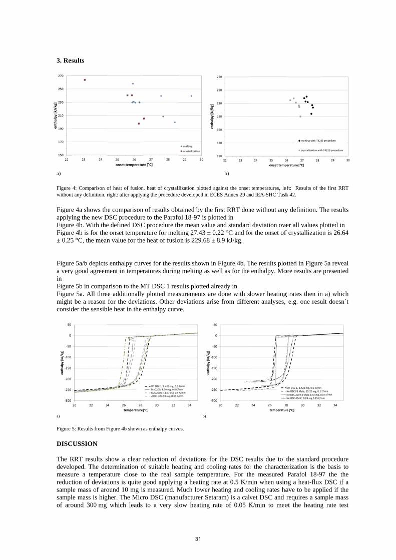
3. Res
a)
Figure without
FigureapplyFigureFigure± 0.25 Figurea veryin FigureFiguremightconsid
a)
Figure
DISC The Rdevelomeasureductsamplsamplof aro
sults
4: Comparison ot any definition, r
e 4a shows thing the new De 4b. With thee 4b is for the5 °C, the mean
e 5a/b depictsy good agreem
e 5b in compae 5a. All thret be a reason der the sensib
5: Results from F
CUSSION
RRT results soped. The deure a tempertion of deviatle mass of arole mass is higound 300 mg
of heat of fusionright: after applyi
he comparisonDSC proceduree defined DSCe onset tempern value for the
s enthalpy curvment in temper
arison to the Me additionallyfor the deviatle heat in the
Figure 4b shown
show a clear termination oature close totions is quite ound 10 mg is
gher. The Micrwhich leads
n, heat of crystalling the procedure
of results obte to the Parafo
C procedure thrature for melte heat of fusio
ves for the resratures during
MT DSC 1 resy plotted meastions. Other denthalpy curv
as enthalpy curve
reduction of of suitable heao the real sagood applyings measured. Mro DSC (manuto a very slo
lization plotted ae developed in EC
tained by the fol 18-97 is plohe mean valueting 27.43 ± 0on is 229.68 ±
sults shown ing melting as w
sults plotted alsurements aredeviations arisve.
b)
es.
deviations foating and cooample temperg a heating ra
Much lower hufacturer Setaow heating r
b)
against the onset CES Annex 29 an
first RRT donotted in e and standard0.22 °C and fo± 8.9 kJ/kg.
n Figure 4b. Twell as for the
lready in e done with slse from differ
r the DSC reoling rates forrature. For thate at 0.5 K/mheating and coaram) is a calvrate of 0.05 K
temperatures, lend IEA-SHC Task
ne without any
d deviation oveor the onset of
he results plotenthalpy. Mo
lower heatingrent analyses,
esults due to tr the charactehe measured min when usinooling rates havet DSC and rK/min to mee
eft: Results of thk 42.
y definition. T
er all values pf crystallizatio
otted in Figureore results are
g rates then ine.g. one resu
the standard perization is thParafol 18-9
ng a heat-fluxave to be apprequires a samet the heating
he first RRT
The results
plotted in n is 26.64
e 5a reveal presented
n a) which ult doesn´t
procedure e basis to 7 the the DSC if a
lied if the mple mass g rate test
31

requirements. Due to the defined procedure results fit quite well with the others despite these differences in technology and sample mass. While the Micro DSC is designed to measure with low heating rates, other DSCs might run at the lower limit of their resolution. It is essential to consider the DSC´s specification when applying the procedure. The RRT revealed also that a standardized calibration is necessary to gain good agreement of results for enthalpy as well as for temperature. It is advisable to calibrate by using several calibration materials and to choose calibration materials which show melting temperatures lower and higher than the PCM´s melting temperature to avoid extrapolation. The calibration has to be done using the heating rate which is determined via the heating rate test and applied to the PCM sample. The correction of baselines is another important step to increase the quality of the measurement results. Some DSC show a baseline drift which makes a comparability of results impossible as this drift is different for every DSC as well as might be different in every measurement. The baseline correction method can eliminate the effect of this baseline drift if the drift linear. The results presented here show very good agreement if it was possible to apply the complete measurement procedure as well as using the recommended analyses. The results presented in Figure 4b and Figure 5ab show good agreement especially for temperatures measured in the melting process. The results for crystallization show larger deviation (Figure 5) due to the statistical behavior of nucleation. Very small deviations can be found for the onset values of the melting peak which is determined to 27.43 °C ± 0.22 K as mean value and standard deviation of all measurements ( Figure 4b). The standard deviation of 0.22 K seems to be an acceptable value considering the different shapes of the measured curves. The determined mean value of onset temperature is a bit lower than the values provided by NIST for pure Octadecane [5]. Nist proclaims melting temperatures in the range between 27.85 °C and 28.35 °C. The mean value for the heat of fusion measured in this work is determined to 229,62 kJ/kg ± 8.9 kJ/kg considering all results, just considering the results shown in Figure 5a it is 232.45 kJ/kg ± 4.32 kJ/kg which is again lower than the values given by NIST (236.15 – 241.65 kJ/kg). These differences might be due to impurities of the used Parafol 18-97. The differences in enthalpy between 20 and 30 °C which is plotted in Figure 5a are less than 10 kJ/kg.
4. Conclusion
The characterization of PCMs using DSC instruments requires a careful procedure to achieve reliable results. The comparison of measurements done for the same material at different institutions using different DSC revealed significant differences without applying a standardized measurement procedure. The measurements done during the development showed that the procedure has to include the calibration, the measurement of the sample and the data analysis, as well. An accurate calibration using the heating rate which will be applied to the sample is essential for the characterization of PCM via DSC. It is also essential to measure PCM with a slow heating and cooling rate. Suitable heating and cooling rates have to be determined by applying a heating and cooling rate test as described. An offset and a drift of the baseline can be eliminated by an analysis with correction of the baseline. The DSC procedure includes: I) the determination of the required heating and cooling rate, II) the calibration of the DSC device under consideration of the determined heating and cooling rate, III) the measurement itself and IV) the data analysis and representation. The procedure is available at [4]. The developed database provides the possibility to uploading, storing and providing high quality PCM-data. It is designed to store measurement data which have been done according the defined DSC procedure. This means that for every measured PCM datasets of three samples and at least three cycles each have to be stored. The user of the data has the possibility to assess the quality of the data and to consider deviations and to compare different material characteristics on a common basis. In general the database addresses users which are doing research on PCM and storages as well as development of PCM systems. In the near future more standard procedure for the characterization of PCMs will be developed. Comparative measurements of thermal conductivity have been just started as well as the characterization of flow behavior and viscosity via rheometers.
32

5. References
[1] Höhne GWH, Hemminger WF, Flammersheim HJ, Differential Scanning Calorimetry, Springer Berlin Heidelberg, ISBN 978-3-642-05593-5, 2003
[2] Lazaro A. et al., Intercomparative tests on phase change materials characterisation with differential scanning calorimeter, Applied Energy 109 (2013) 415–420
[3] www.pcm-ral.de [4] https://thermalmaterials.ise.fraunhofer.de/ [5] http://webbook.nist.gov/chemistry/name-ser.html Acknowledgement
Great thanks to the entire group participating in the development by spending so much time doing the DSC measurements and also great thanks for the fruitful discussions over the last 6 years. Many thanks also to the German Federal Ministry of Economics and Technology for funding the participation of Fraunhofer ISE in the frame of the national project KOLAN FKZ 03ESP357B. The research leading to these results from University of Lleida has received funding from the European Commission Seventh Framework Program (FP/2007-2013) under grant agreement n° PIRSES-GA-2013-610692 (INNOSTORAGE) and from the European Union’s Horizon 2020 research and innovation program under grant agreement No 657466 (INPATH-TES ). The UdL authors would like to thank the Catalan Government for the quality accreditation given to their research groups GREA (2014 SGR 123) The University of Zaragoza thanks the Spanish Government for the partial funding of this work within the framework of research projects ENE2008-06687-C02-02, ENE2011-28269-C03-01 and ENE2014-57262-R
33

SHC 2015
Advanced numerical modelling techniques to tune the properties of heat
storage materials for optimal reactor performance
S.V.Gaastra-Nedea1, C.C.M. Rindt
1 A. König-Haagen
2, R. R. Kasibhatla
2, D.
Brüggemann2, Pablo Dolado
3, Ana Lazaro
3, Erwin Franquet
4
1Technical University Eindhoven TU/e, the Netherlands, Phone: +31402475410, email:
[email protected], 2University of Bayreuth, Center of Energy Technology (ZET), Department of Engineering
Thermo¬dynamics and Transport Processes (LTTT), [email protected] 3University of Zaragoza, [email protected]
4Pau University, 5INSA Lyon, [email protected]
Heat storage materials like thermo-chemical materials (TCM) and phase change materials (PCM) can be
successfully used for long-term heat storage in the built environment and/or industry, dependent on their
loading temperatures, energy densities, power densities and recyclability. To gain more insight into the heat
and mass transfer processes taking place in these materials during charging and discharging, numerical
modeling is needed ranging from the molecular- and micro-scale up to the macro- and reactor-scale.
A review of the activities within the working group A3 in the framework of IEA SHC Task 42 / ECES
Annex 29 (Task 4229) related to different level modeling and simulations is given here. As an example of
activity for developing and testing numerical models to understand and optimize material behavior, we will
investigate MgCl2 hydrates. Molecular models are used to check the effect of water vapor pressure on
hydrolysis and dehydration reaction. The results of the water diffusivity in the crystalline structure can
further be used to higher level models in the working group and in a later stage to optimize specific
properties of the storage materials with respect to their usage.
Keywords: multi-scale simulations, thermochemical materials, molecular simulations
1. Introduction
Within the framework of IEA-SHC Task 42 and IEA-ECES Annex 29, the activities in the Numerical
Modeling working group are aimed at developing and testing numerical models that help to understand and
optimise the material behaviour and the dynamic behaviour of compact thermal energy storage systems and
components based on Phase Change Materials (PCM’s) and Thermo Chemical Materials (TCM’s).
Ultimately, these numerical models could help to find ways to optimise the materials in combination with
the system components. The activities in this working group help to lay the foundation for such models.
The Working Group includes the following activities: a) Micro-scale modeling, b) Meso-scale modeling, c)
Macro-scale modeling, d) Multi-scale approach, e) Thermo-mechanical modeling, f) Reactor models.
The knowledge of the thermodynamic properties and the dynamical behavior of all the materials and the
components is the basis for the design of a storage device and the different level numerical models can help
to understand how the limiting parameters can or should be adapted for the assigned task, reducing the
number of time consuming and cost intensive experiments.
34

1.1.Molecular investigation of salt hydrates
An example is given in this overview, focusing as staring point on molecular investigation of salt hydrates.
Magnesium salt hydrates are potential candidate materials for seasonal heat storage systems. MgCl2x6H2O
and MgSO4x7H2O are particularly interesting due to their high energy storage densities (roughly 2-3
GJ=m3[1]) and their wide availability. Magnesium salts serve as excellent thermochemical heat storage
materials, however the performances of such systems are dependent on the material properties and the
kinetics of hydration an dehydration reactions. Apart from the crystal structure and composition, the
surface defects and dislocations show a large impact on the hydration/dehydration behavior[1]. MgSO4
hydrates are known to exhibit slow kinetics and the presence of meta-stable states[2]. MgCl2 hydrates
show faster kinetics, but the hygroscopic chloride salts tend to form a gel-like material during hydration or
the formation of a solution[2].
Besides, the dehydration of MgCl2 hydrates is usually accompanied by hydrolysis reaction with the release
of HCl, which can potentially damage the material as well as the equipment, and makes the material also
less suitable for use in the built environment.
The information about the possibility of the hydrolysis reaction, and its preference over dehydration
remains ambiguous and the characterization of the dehydration process which is essential for utilisation.
1.2. Macro-encapsulated latent thermal energy storage
Within the contributing project MALATrans a macro-encapsulated latent thermal energy storage system is
being designed. To study the melting and solidification processes within the macro capsules a detailed
numerical model is developed. Implemented in the OpenFOAM framework this model is capapble of
predicting the influence of the settling of the solid phase change material (PCM), the natural convection
taking place in the liquid regime of the PCM and the air phase locked above the PCM. Due to the high
numerical effort of this model simplified models are needed to study the influence of the heat transfer fluid
(HTF) flow around the capsules and the overall behaviour of the storage unit. To investigate the latter
strongly simplified computational fluid dynamics (CFD) models as well as 2-D and 1-D system models are
evolved. In addition a exergetic avaluation method is developed to predict the optimization limit and the
influence of different material parameters on the performance of the storage unit itself and on the overall
system [4]. In the following the detailed CFD model as well as the strongly simplified CFD models are
discussed more explicitly.
1.3 Numerical models to simulate the thermal performance of PCM-air heat exchangers
Uncertainty studies applied to theoretical models are a practice that allows an analysis of the behavior of
the model, calculating the uncertainty in the model outputs induced by the uncertainty in the inputs. This
improved knowledge of the theoretical model against these changes helps to know what are the most
critical factors as model inputs and, therefore, indicates what should be more controlled in its determination
or measurement. In the field of computer simulation of thermal energy storage (hereafter TES) systems by
phase change materials (hereafter PCM) that exchange heat with air, it can get to work with important input
data uncertainties. Most of these uncertainties are related to the value of air temperature or the airflow at
the inlet of the TES unit but so are the properties of the PCM
1.4 CFD models for material and thermophysical properties of PCM storage systems
Development of new applications in the storage field has increased the needs for numerical predictions, be
it for the design or the operating management of the associated technologies. To summarize, these
calculations can either concern the material and the corresponding thermophysical properties or the whole
system and its global features. In the first case, numerical calculations are coupled with some
measurements through an inverse technique so as to determine the properties of the material. In the same
time, a parametric analysis is also conducted. Then these properties, and the possible uncertainties linked to
the key parameters obtained from the parametric analysis, are used to simulate a storage and observe the
deviations in function of the input parameters.
35
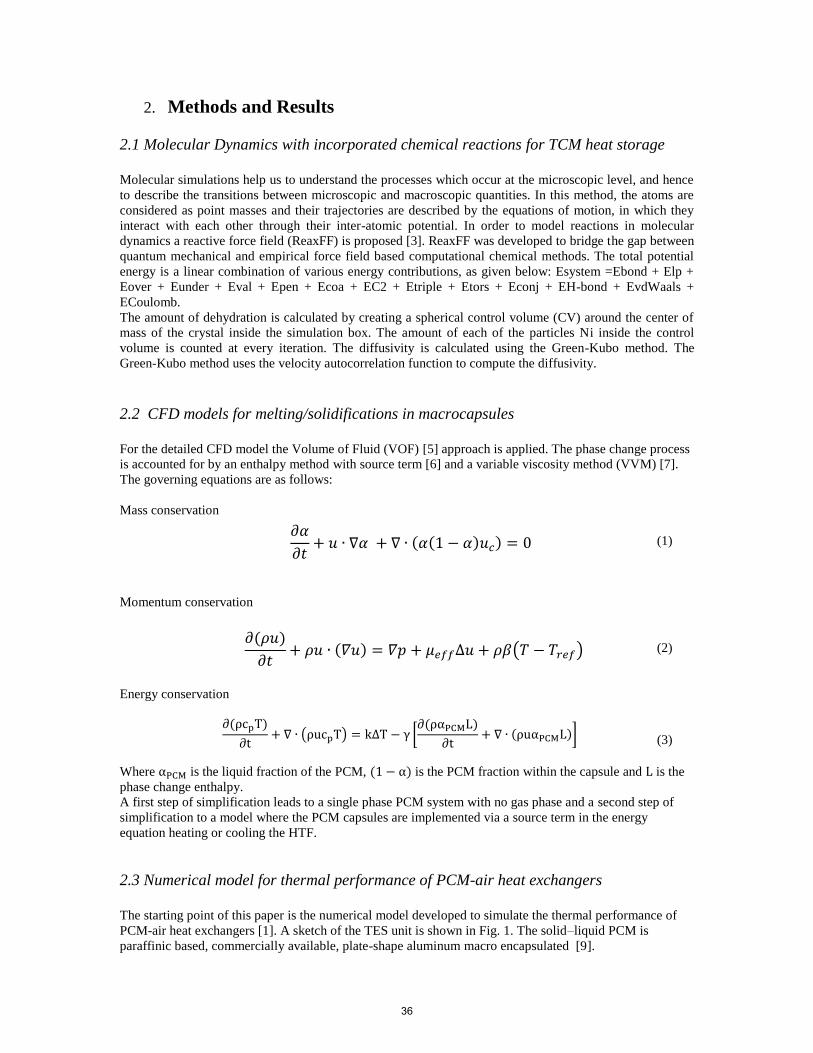
2. Methods and Results
2.1 Molecular Dynamics with incorporated chemical reactions for TCM heat storage
Molecular simulations help us to understand the processes which occur at the microscopic level, and hence
to describe the transitions between microscopic and macroscopic quantities. In this method, the atoms are
considered as point masses and their trajectories are described by the equations of motion, in which they
interact with each other through their inter-atomic potential. In order to model reactions in molecular
dynamics a reactive force field (ReaxFF) is proposed [3]. ReaxFF was developed to bridge the gap between
quantum mechanical and empirical force field based computational chemical methods. The total potential
energy is a linear combination of various energy contributions, as given below: Esystem =Ebond + Elp +
Eover + Eunder + Eval + Epen + Ecoa + EC2 + Etriple + Etors + Econj + EH-bond + EvdWaals +
ECoulomb.
The amount of dehydration is calculated by creating a spherical control volume (CV) around the center of
mass of the crystal inside the simulation box. The amount of each of the particles Ni inside the control
volume is counted at every iteration. The diffusivity is calculated using the Green-Kubo method. The
Green-Kubo method uses the velocity autocorrelation function to compute the diffusivity.
2.2 CFD models for melting/solidifications in macrocapsules
For the detailed CFD model the Volume of Fluid (VOF) [5] approach is applied. The phase change process
is accounted for by an enthalpy method with source term [6] and a variable viscosity method (VVM) [7].
The governing equations are as follows:
Mass conservation
(1)
Momentum conservation
(2)
Energy conservation
∂(ρcpT)
∂t+ ∇ ∙ (ρucpT) = k∆T − γ [
∂(ραPCML)
∂t+ ∇ ∙ (ρuαPCML)]
(3)
Where αPCM is the liquid fraction of the PCM, (1 − α) is the PCM fraction within the capsule and L is the
phase change enthalpy.
A first step of simplification leads to a single phase PCM system with no gas phase and a second step of
simplification to a model where the PCM capsules are implemented via a source term in the energy
equation heating or cooling the HTF.
2.3 Numerical model for thermal performance of PCM-air heat exchangers
The starting point of this paper is the numerical model developed to simulate the thermal performance of
PCM-air heat exchangers [1]. A sketch of the TES unit is shown in Fig. 1. The solid–liquid PCM is
paraffinic based, commercially available, plate-shape aluminum macro encapsulated [9].
𝜕𝛼
𝜕𝑡+ 𝑢 ∙ ∇𝛼 + ∇ ∙ (𝛼(1 − 𝛼)𝑢𝑐) = 0
𝜕(𝜌𝑢)
𝜕𝑡+ 𝜌𝑢 ∙ (𝛻𝑢) = 𝛻𝑝 + 𝜇𝑒𝑓𝑓∆𝑢 + 𝜌𝛽(𝑇 − 𝑇𝑟𝑒𝑓)
36

Thus, in this study the following goals have been set:
a) To analyze the behavior of the theoretical model to modifications in the input variables/parameters;
b) To identify the most critical factors acting as inputs in the model;
Fig. 1. TES unit sketch, the PCM-air heat exchanger.
For the current study, the following parameters that introduce uncertainty in the results, were considered
and classified into three groups:
-Material properties (parameterized h–T curve, and thermal conductivity curve);
-Air conditions at the inlet of the TES unit (temperature and airflow);
-Geometric parameters (PCM plate thickness and width of the air gap between plates).
The determination of the thermophysical properties of PCM has several accepted methodologies
(differential scanning calorimetry or DSC, T-history, adiabatic calorimetry). In any case, the results of
these measurements are not always consistent between different authors [10]. Because of the importance of
both, the enthalpy and the thermal conductivity curves as functions of temperature, these two properties are
to be considered for this analysis. Thus, the importance of the knowledge of the material properties is
studied. To facilitate the analysis of the results a parameterization of the h–T curve is proposed. This kind
of curves can be described by a sigmoidal function. The advantage of using such a parameterization is that
it allows defining parameters that can be associated with the most characteristic aspects of the h–T curve.
As shown in Fig. 2 the following associations of the curve parameters can be taken:
hs, the value of enthalpy in solid phase (just before the start of the solid–liquid phase change);
hl, the enthalpy in the liquid phase (just after finishing the solid–liquid phase change);
ΔT, amplitude of the thermal window (corresponding to the temperature range in which the PCM is
changing phase);
Tsl, average phase change temperature of PCM.
Fig. 2. Generic sigmoidal function applied to an enthalpy–temperature curve.
However, for a better agreement of the parameterized curve with that one obtained in the laboratory, the
sigmoidal function is combined with a linear function. Thus, a new parameter is considered. The parameter
37

b is associated with the slope of the curve in all-liquid phase and all-solid phase (sensible heat). The setting
is as shown in Eq. (1). The range of uncertainty assumed for all these parameters is shown in Table 1. The
confidence level is 97.5%.
T
TT
sls
sl
e
hhhTbh
1
·
Eq. 1
Table 1. Parameters setting of the enthalpy-temperature curve
Parameter b ΔT hl Tsl
Related with Slope of the
sensible heat part
Thermal window Latent heat Taverage of phase
change
Reference value 3 kJ/(kg·K) 0.9 ºC 170 kJ/kg 27 ºC
Uncertainty ± 15 % ± 0.2 ºC ± 20 kJ/kg ± 1 ºC
Effect on h-T
curve
2.4 Numerical methods for for material and thermophysical properties of PCM storage
systems
The calculations are based on the classical balance equations written in the context of fixed grid methods
[11, 12, 13, 14]. In the conductive regime, it thus corresponds to the classical energy equation:
In the convective regime, one considers an incompressible flow of a Newtonian fluid with Boussinesq
approximation:
With the porosity function
This set of partial differential equations is solved directly using a finite volume method, either explicitly or
implicitly, or is implemented in the C++ OpenFOAM environment.
Y
X
yt
yo
xo
Y
X
yt
yo
xo
Y
X
yt
yo
xo
Y
X
yt
yo
xo
38

3. Results
3.1 Molecular dynamics results
The simulations show that both H2O and some HCl are released during dehydration, whereas the Mg atoms
remain inside the crystal at all times. The results of the simulations indicated the number of each type of
atoms inside the control volume (with radius RCV = 50 A) during dehydration at 450K and 550K .
Comparing the results for the two different temperatures, it can be seen that at 550 K more H2O is released
and also slightly more HCl. This result is consistent with the results obtained from the equilibrium analysis.
The dehydration behaviour at 450 K for different water vapour pressure was analysed in three different
cases. The number of added water molecules to the vacuum space is for (a) 0, for (b) 300 and for (c) 600.
From the three simulations, it follows that the dehydration kinetics decreases if the H2O pressure is
increased.
Fig 3. Number of atoms in the control volume during dehydration at 450 K. The number of added water
molecules to the vacuum space is for (a) 0, for (b) 300 and for (c) 600.
The diffusivity of water out of the crystal is also measured for three different cases. It is already mentioned
that a higher water vapor pressure results in less water evaporated from the crystal. It is found that indeed
the highest diffusivity is found at the lowest water vapor pressure, and vice versa, the lowest diffusivity at
the highest water vapor pressure. In Table 4.2, the water diffusivity is calculated for two different radii of
the control volume. A control volume radius of 25 ˚Acontains mostly the core of the crystal, while a radius
of 30 ˚Aalso accounts for surface effects. Comparing both cases, it can be seen that the diffusivity increases
towards the surface of the crystal. Namely, the atoms are less constrained at the surface and hence they
move more freely, resulting in a higher diffusivity.
39

3.2 Numerical models results for melting/solidifications in macrocapsules
Figure 4 shows a comparison of results of the detailed CFD model with experimental results for the melting
of PCM RT 35 HC Paraffin with initially 303 K and a boundary wall temperature of 315 K. The geometry
is a 40x40x40 mm cuboid and initially 75% capsule volume are filled with PCM.
Figure 4: Melt front of a capsule filled with PCM and Air.
The heat transfer rate of the lower wall starts equal to that of the side walls and due to close contact melting
it increases to almost 90 % of the overall heat transfer rate. In addition it is found that the influence of the
locked air phase can be satisfyingly considered by an one-phase model with an appropriate boundary
condition at the top wall. A comparison of the melting time for different capsule geometries with constant
volume yields that a cuboid is favourable over a cylinder and a sphere.
Parallel to the heat transfer modelling the pressure drop and flow distribution within a storage unit is
simulated. Whereas on the left hand side of Figure 5 a detailed fluid flow approach is applied, there is a
packed bed porosity approach for modelling the permeability of the heat transfer fluid in the sphere packing
on the right hand side. The results depict that the pressure drop within the storage unit will be very small,
but care has to be taken to avoid a bypass flow at the outer walls.
40

Figure 5: Flow distribution within a lab scale storage unit
These strongly simplified CFD models are also taken to implement the source term accounting for the
thermal energy stored in the capsules. This source term is implemented as a function of the enthalpy within
the capsule and the HTF temperature. Validating these models is work in progress.
3.3 Numerical model for thermal performance of PCM-air heat exchangers
Figure 6 shows the influence of these parameters in the solution of both the average heat rate expressed in
terms of SRC and also indicates the source of each of these parameters. Analyzing the results regarding
heat rate, it can be observed that the most influential parameter among the PCM properties is the average
phase change temperature (furthermore being the most influential of all considered factors): the lower the
temperature, the higher the average heat rate. This result is expected, while decreasing the average phase
change temperature, the temperature gradient between the air and the PCM is more pronounced and
therefore increasing both the maximum exchanged heat rate and the average heat rate (provided that the
PCM is not melted in less than one hour). It can also be observed the importance of the parameter hl
(associated with the latent heat of the PCM in the parameterization of the h-T curve). These results
emphasize the importance of a careful determination of the PCM enthalpy-temperature curve or its tuning.
On the other hand, the analysis stresses the importance of both the inlet air temperature and the air flow.
The air temperature is a crucial factor because in many cases designers will use temperature data from the
given area where the TES unit is going to be located (hourly values recorded at a weather station and used
as representative values for the specific location) what may become a significant source of error. Regarding
the air flow, as it is strongly linked to the convection coefficient, its weight in the heat transfer process is
substantial. Thus, it becomes another source of error to consider. From the results, the effect in the
responses of reducing the associated uncertainty with the relevant parameters was also tested.
41

Figure. 6. SRC representation for each of the analyzed factors in the response Q average,1h
3.4 Numerical results for material and thermophysical properties of PCM storage
systems
After the inversion process, one may be capable to determine the enthalpy function of some material [12]
and its possible evolution during thermal cycling, as plotted in Fig 7.
Figure 7. Enthalpy functions obtained with the inverse process during lifetime of a PCM
Given these thermophysical properties, the goal is then to calculate the impact on the performances of a
thermal storage (all the others parameters being obviously kept constant) for different cycle [14, 15]. On
Figure 8 are shown the fill factor temporal evolution, this one giving a good overview of the amount of
energy available in the storage and permitting also to study the charge/discharge dynamics and therefore
the input/ouput powers of the storage.
42

a) One cycle b) Five cycles
Figure 8. Temporal evolution of the fill factor for various cycles using the different enthalpy functions
corresponding to the PCM evolution with time
4. Conclusions and recommandations
An overview of all the numerical modelling techniques available on the micro-, meso- and macro-scale
within the working group and the results from molecular to the larger scale modelling is outlined in the
paper. For the molecular modelling, the MD simulations for a particular system (MgCl2 hydrates) results show a
similar trend with those found from the thermodynamic equilibrium analysis. A higher water vapor
pressure counteracts both the dehydration and the hydrolysis reaction, whereas a higher temperature
increases the amount of dehydration and hydrolysis. However quantitatively, also some differences are
observed. It was predicted that hydrolysis occurring from the di-hydrate was unlikely under the conditions
of a heat storage system, while the MD simulations show that, up until a certain water vapor pressure (20-
40 mbar), HCl is formed. A comparison of the MD results for three different water vapor pressures, also
showed that a higher water vapor pressure ensures a higher crystal density, a more crystalline structure and
a lower diffusivity of water.
In the case of the Numerical model for thermal performance of PCM-air heat exchangers , we have
analyzed the importance of the variables that introduce uncertainty into the simulations run with the
theoretical model. This study can be performed on a larger number of input variables/parameters that
potentially provide uncertainty (PCM mass, fan power, roughness of the plate, material properties and
characteristic parameters of the case, other PCM properties). Once you have a theoretical model developed,
the methodology is worth to assess not only the accuracy of the model inputs but also state which are the
more influencing factors for your model at system level, therefore marking the most relevant properties of
the storage material (if considered in the model) to further tune.
From the numerical results of material and thermophysical properties of PCM storage systems, it is clear
that some deviation may occur if the enthalpy function does not perfectly fit the real behavior of the
material. This may arise first if the thermophysical characterization of the PCM is not correctly conducted,
and therefore it is clear that this step has to be further investigated and improved so as to define reliable
h(T )
0.0
0.1
0.2
0.3
0.4
0.5
0.6
0.7
0.8
0.9
Fil
lFac
tor
(-)
0 200 400 600 800 1000 1200 1400
Time (s)
2%M 4%M 6%M CP
54%2K
h(T )
h(T )
N aN O3
Bin2K Bin5K Bin8K CP
0.0
0.2
0.4
0.6
0.8
1.0
1.2
FillFac
tor
(-)
0 1000 2000 3000 4000 5000 6000 7000
Time (s)
Bin2K Bin5K Bin8K CP
Bin2K Bin5K Bin8K CP
t = 3000s %er el = F F2K ( t= 3000 s)− F FC P ( t= 3000 s)F F2K (t= 3000 s)
43

methods. Secondly, such a bias could also come from the degradation of the product during its lifetime,
independently of the precision of the characterization method, and consequently one has either to search for
very stable materials (which may be difficult) or to determine the temporal evolution of the thermophysical
properties, which is solely done and should thus be also further investigated.
5. Literature
[1] M. A. Stanish and D. D. Perlmutter, AIChE J. 30, 557 (1984).
[2] C. J. Ferchaud, H. A. Zondag, J. B. J. Veldhuis, and R. de Boer, J. Phys: Conf.Series 395, 012069 (2012).
[3] K. Chenoweth, A. C. van Duin, and W. A. Goddard, J. Phys. Chem. A 112, 1040 (2007)
[4] A. König-Haagen; F. Rösler; D. Brüggemann, "Exergetic analysis of thermal energy storages in thermodynamic
systems.” In: Eurotherm Seminar #99: Advances in Thermal Energy Storage, 978-84-697-0467-7, Lleida (Spain), May
2014
[5] W.F. Noh; P. Woodward "SLIC (Simple Line Interface Calculation)” In: Proceedings of 5th International
Conference of Fluid Dynamics, edited by A. I. van de Vooren & P.J. Zandbergen 1976
[6] C.R. Swaminathan and V.R.Voller,“On the Enthalpy method”, Int.J.Numerical Methods for heat and fluid flow
1993.
[7] D.K., Gartling, “Finite Element Analysis of Convective Heat Transfer Problems with Change of Phase.” United
States: N. p., 1978
[8] P. Dolado Bielsa, A. Lázaro Fernández, J.M. Marín Herrero, B. Zalba Nonay, Characterization of melting and
solidification in a real scale PCM-air heat exchanger: Numerical model and experimental validation, Energy
Conversion and Management 52 (2011) 1890-1907.
[9] P. Dolado Bielsa, A. Lázaro Fernández, J.M. Marín Herrero, B. Zalba Nonay, Characterization of melting and
solidification in a real-scale PCM-air heat exchanger: Experimental results and empirical model. Renewable Energy 36
(2011) 2906-2917
[10] IEA Task Annex 42 24, in: http://task42.iea-shc.org/ access date: November 13th, 2015
[11] B. Basu and A.W. Date. Numerical modelling of melting and solidification problems - A review. Sadhana,
13(3):169–213, 1988
[12] Franquet E., Gibout S., Bédécarrats J.-P., Haillot D., Dumas J.-P. (2012) Inverse method for the identification of
the enthalpy of phase change materials from calorimetry experiment. Thermochimica Acta, 546, pp 61–80
[13] H. Hu and S. A. Argyropoulos. Mathematical modelling of solidification and melting: a review. Modelling Simul.
Mater. Sci. Eng., 4(4), 1996
[14] Pernot E., Franquet E., Lomonaco A., Haillot D., Bédé- carrats J.-P. (2015) Numerical modelling of a latent
thermal energy storage system for high efficiency processes. ECOS 2015
[15] Pernot E., Franquet E., Lomonaco A., Haillot D., Bédé- carrats J.-P. (2015) Latent heat thermal energy storage
system: numerical analysis of the influence of the enthalpy function on the charge/discharge processes. Greenstock
2015
[16] M. Salcudean and Z. Abdullah. On the numerical modelling of heat transfer during solidification processes.
International Journal for Numerical Methods in Engineering, 25(2):445–473, 1988
[17] V. R. Voller, C. R. Swaminathan, and B. G. Thomas. Fixed grid techniques for phase change problems: A review.
International Journal for Numerical Methods in Engineering, 30(4):875–898, 1990
44

Available online at www.sciencedirect.com
ScienceDirect
Energy Procedia 00 (2015) 000–000
www.elsevier.com/locate/procedia
1876-6102 © 2015 The Authors. Published by Elsevier Ltd.
Peer-review by the scientific conference committee of SHC 2015 under responsibility of PSE AG.
SHC 2015, International Conference on Solar Heating and Cooling for Buildings and Industry
IEA SHC Task 42 / ECES Annex 29 – Working Group B:
Applications of Compact Thermal Energy Storage
Wim van Helden1, Motoi Yamaha
2, Christoph Rathgeber
3, Andreas Hauer
3, Fredy
Huaylla4, Nolwenn Le Pierrès
4, Benoit Stutz
4, Barbara Mette
5, Pablo Dolado
6, Ana
Lazaro6, Javier Mazo
6, Mark Dannemand
7, Simon Furbo
7, Alvaro Campos-Celador
8,
Gonzalo Diarce8, Ruud Cuypers
9, Andreas König-Haagen
10, Stephan Höhlein
10, Dieter
Brüggemann10
, Benjamin Fumey11
, Robert Weber11
, Rebekka Köll1, Waldemar Wagner
1,
Xavier Daguenet-Frick12
, Paul Gantenbein12
, Frédéric Kuznik13
1AEE INTEC, Feldgasse 19, 8200 Gleisdorf, Austria; Phone: +31 6 2014 3224, [email protected]; 2Chubu University, Nagoya, Japan; 3ZAE Bayern, Garching, Germany; 4LOCIE Laboratory, CNRS-Savoie Mont Blanc University, France;
5ITW, University of Stuttgart, Germany; 6University of Zaragoza, Spain; 7DTU Technical University of Denmark; 8University of the Basque
Country, UPV-EHU, Spain; 9TNO, Delft, the Netherlands; 10University of Bayreuth, Germany; 11EMPA, Dübendorf, Switzerland; 12HSR-SPF,
Rapperswil, Switzerland; 13Universitée de Lyon, INSA-Lyon, CETHIL, Villeurbanne, France;
Abstract
The IEA joint Task 42 / Annex 29 is aimed at developing compact thermal energy storage materials and systems. In Working
Group B, experts are working on the development of compact thermal energy storage applications, in the areas cooling, domestic
heating and hot water and industry. The majority of application projects were in the field of room heating and domestic hot water.
In this article, an overview is given of a large number of applications. The storage technologies used in the applications are latent
heat storage, open and closed solid sorption, liquid sorption and salt hydrates and composites thereof. On a broad front, a lot of
progress was made in the development of components and systems, providing knowledge and experience regarding the design,
numerical modeling, building, testing and economical assessing of components and storage systems. Most important findings are
that the interaction of storage materials with the materials of components can be deciding for the technical feasibility, that a
number of components, like reactor, heat exchangers and evaporators are less understood than initially thought and need more
45

Wim van Helden et al./ Energy Procedia 00 (2015) 000–000
development, that the inclusion of storage materials in systems generate new challenges like the occurrence of non-condensable
gases and thermo-mechanical effects and that standardized and simplified system approaches are needed.
© 2015 The Authors. Published by Elsevier Ltd.
Peer-review by the scientific conference committee of SHC 2015 under responsibility of PSE AG.
Keywords: themal energy storage, applications; PCM; TCM;
1. Introduction
Within the Working Group B (Applications) of the IEA joint Task 42 /Annex 29, a large number of experts from
more than 20 research organisations work on applications of compact thermal energy storage technologies.
Application fields are cooling, room heating/domestic hot water and thermal storage for industry. The main
challenges in the development of applications are in finding an optimal connection between the storage material and
the other materials, the components and the system configuration. The problems to be solved are in the area of
materials compatibility, like corrosion protection, prevention of side reactions and cycling stability; in the area of
component design, with heat and mass transfer optimisaton; and in the area of system design with control strategies
and cost minimisation.
Thermal storage for cooling applications is the most advanced. There are numerous examples of ice storage
systems, running to get a higher system performance or to enable a shift of electricity consumption from daytime to
nighttime. Challenges in these systems are the integration of novel PCM with somewhat higher melting
temperatures than water and the system optimisation in connection with electricity grids and heating networks.
Most application developments in T4229 are in the area of thermal energy storage for room heating and domestic
hot water preparation. Here, there is a broad collection of storage technologies and system concepts being developed
and tested. Phase change materials and thermochemical materials are applied as active material in open and closed
systems.
A third field of application is in the transportation of residual or waste heat to a remote user by compact thermal
storage technologies. Due to scaling effects, this application is first developed for industrial users.
In the Task 42 / Annex 29, special attention is paid to the collaboration between materials researchers and system
engineers. A compact thermal energy storage material only has value in a certain application, and the application
will imply certain design conditions on the storage material. A first step towards a better collaboration and
interaction is for system engineers to understand how materials researcher evaluate the properties of a storage
material, and for materials experts to understand the practical implications of integrating material into a storage
system. In the Task, work is done to couple the material properties to system performance, although this in most
cases is far from straightforward. For sorption storage technologies, an approach was set up using 4 typical
operating temperatures with which the operation boundary conditions are determined and the performance of a
storage material in an application can be determined [Hauer2015].
Given a certain application, it is necessary to have a common basis for determining the performance of different
storage technologies. To this end, a design has been made of a set of Key Performance Indicators KPI’s of compact
thermal energy storage for seasonal storage. In future, these KPI’s will be a valuable tool for comparison of different
thermal storage concepts.
In the next chapters, a number of developments that were undertaken by experts from the Task 42 /Annex 29 are
shortly described. Although numerous, these are not all the system concepts or technologies developed in
connection to the Task. They give, however, a good view of all the developments presently underway inlcuding the
challenges that are connected to them.
46

Wim van Helden et al./ Energy Procedia 00 (2015) 000–000
2. Low temperature storage applications
In the Task 42 /Annex 29 the division between application areas was determined by the typical operational
temperature ranges: low, medium and high temperature. A low temperature, the typical application is cooling, with
temperatures below 20 °C. Medium temperature applications are room heating and domestic hot water, with
temperatures between 20 °C and 100 °C. Above 100 °C, the industry applications are situated.
Two developments in the low temperature application field will be described: a latent heat storage in a solar
thermally driven cooling and heating system, and a very large ice storage system for building cooling in Japan.
2.1. Solar Heating and Cooling with Absorption Chiller and Latent Heat Storage; ZAE Bayern
The latent heat storage is integrated into a thermal solar heating and cooling system and supports the dry air
cooler in the heat rejection system on hot days during summertime to ensure a constant cooling water return
temperature of 32 °C. The charged heat is dissipated to the ambient during off peak hours or nighttime when more
favorable ambient conditions are available. In wintertime the latent heat storage serves as an additional low
temperature storage to buffer solar surplus at constant storage temperatures, leading to low collector temperatures
and thus high solar gain. Calcium chloride hexahydrate with a melting temperature of about 29 °C is used as PCM
and a propylene glycol - water mixture as heat transfer medium [Helm2014].
Figure 1: System scheme of the solar heating and cooling installation at ZAE Bayern
The heat storage material (Calcium chloride hexahydrate) has a volume of 1 m³, and the gross volume incl. the
storage container accounts for 1.9 m³. The realized storage capacity between 22 and 36 °C is 83 kWh. In the case of
discharging, 14 kW peak power can be extracted from the storage.
During the monitoring period the two latent heat storage modules have undergone over 800 loading and
unloading cycles under real conditions. Due to the use of the latent heat storage the cooling water return temperature
did not exceed 33.5 °C despite dry air cooling and ambient temperatures above 32 °C. In heating mode about 15 %
of the overall heat demand has been provided by the latent heat storage.
2.2. Cooling of building; Nagoya Station; Chubu University
Ice thermal storage systems have been popular thermal energy storage systems in Japan since mid-90s. More than
10 thousand systems varying from small ones to huge ones are installed. This example is a district heating and
cooling (DHC) facility for an area where the world’s largest station building is situated. This DHC adapts the Eco
friendly heat supply system which saves energy by combination of “Ice storage system (electricity)” and waste heat
HEATING / COOLINGSYSTEM
CHILLER
LATENTHEAT
STORAGE
DRY AIRCOOLER
SOLARSYSTEM
AUX.BOILER
HOTWATERTANK
15°C18°C
32°C
90°C
80°C
40°C32°C
36°C
32°C
36°C
40°C
50 % dryheat rejection50 % loadinglatent heat
storage
SOLAR
COOLING
HEATING / COOLINGSYSTEM
CHILLER
LATENTHEAT
STORAGE
DRY AIRCOOLER
SOLARSYSTEM
AUX.BOILER
HOTWATERTANK
15°C18°C
32°C
90°C
80°C
40°C32°C
36°C
32°C
36°C
40°C
50 % dryheat rejection50 % loadinglatent heat
storage
SOLAR
COOLING
47

Wim van Helden et al./ Energy Procedia 00 (2015) 000–000
from the “Cogeneration system (Natural gas)”. Energy management is adopted to enhance energy efficiency by
continuous analysis of operational data.
As cooling demand in the summer time is at a high plateau from 11:00 to 18:00, by discharging the cold heat
stored at night time, the system could reduce the operation hours of the chillers and contribute to energy saving. The
electricity demand curve resulted to be flat. Its value is around 3 to 4 MW contributing to load levelling and
reduction of operational cost.
The objective of the system is to shave the peak to off-peak hours and take advantage of the tariff difference
between day and night. By producing ice at night time utilizing low cost night time electricity and using it to
produce cold water in the daytime, this Ice Storage System contributes to cost reduction and load levelling. The
facility has ice storage tanks of 1,266 m3 with 49GWh capacity.
Figure 2: Schematic diagram of the ice tank storage system and photo of the storage tank room
3. Medium temperature storage applications
Typically, the medium temperature applications have the function to provide room heating, domestic hot water or
both. In this area, most developments take place with a variety of storage technologies. These range from phase
change, solid and liquid sorption to salt hydrate systems.
3.1. Closed absorption system with sodium hydroxide; EMPA and HSR-SPF
In Line B of the EU financed project COMTES a heat storage system based on absorption of vapor by a liquid in
a closed process is developed. The working pair is aqueous sodium hydroxide (NaOH-H2O) and water. In the
project a demonstrator was built, functioning as a hybrid system [Fumey2013]. It is composed of hot water tanks as
sensible heat storage for short term storage of several days and an absorption heat storage unit for long term storage
of weeks and months. The complete system is built into a shipping container on which solar thermal vacuum tube
collectors are installed for solar heat harvesting. The Figure 3 shows the outside of the container and the collector
field. The absorption system consists of a power unit in the form of a heat and mass exchanger connected to a
capacity unit made up of three tanks containing the sorbent NaOH-H2O in its charged and discharged state as well as
the sorbate water. Sorbent and sorbate are pumped to and from the heat and mass exchanger with gear pumps in
both the charging and discharging process steps.
48

Wim van Helden et al./ Energy Procedia 00 (2015) 000–000
Figure 3: Picture of the demonstrator container from the outside with the vacuum tube
collector field.
Figure 4: CAD picture of the hybrid system
indicating components and function.
Figure 5: Picture of the demonstrator heat and mass exchanger connected to the storage tanks.
The design of the required heat and mass exchanger for desorption and absorption has proven to be challenging.
For the sake of a compact build, a single unit for both process steps was pursued [Daguenet-Frick2015]. The falling
film tube bundle approach followed in this development has shown poor power performance in the absorption
(discharging) process [Fumey2015]. In contrast to this, in the desorption (charging) process power performance
according to design calculations was reached. Nevertheless the desired concentrations in absorption as well as
desorption were not reached. This is essential for a high system energy density. In the continuation of this work, the
concept of a single unit combining the discharging and the charging process steps has to be reconsidered and
possibly rejected. In case of the combined evaporator and condenser unit the concept can be followed.
3.2. Solid sorption solar seasonal storage; AEE INTEC, ITW, TH Wildau, Vaillant
In the EU funded project COMTES, in Development Line A, a system is developed, tested and optimized that is
based on closed sorption of a solid material. The used working pair is zeolite 13XBF and water. In a first phase the
heat and mass transfer in a prototype vessel with about 180 kg of zeolite was numerically modelled and experiments
were carried out to validate the model. With this model, the heat exchanger geometry for the two larger vessels
(each 1000 litres, 705 kg zeolite) was optimised. The system was built up, containing also 16 m2 of vacuum tube
49
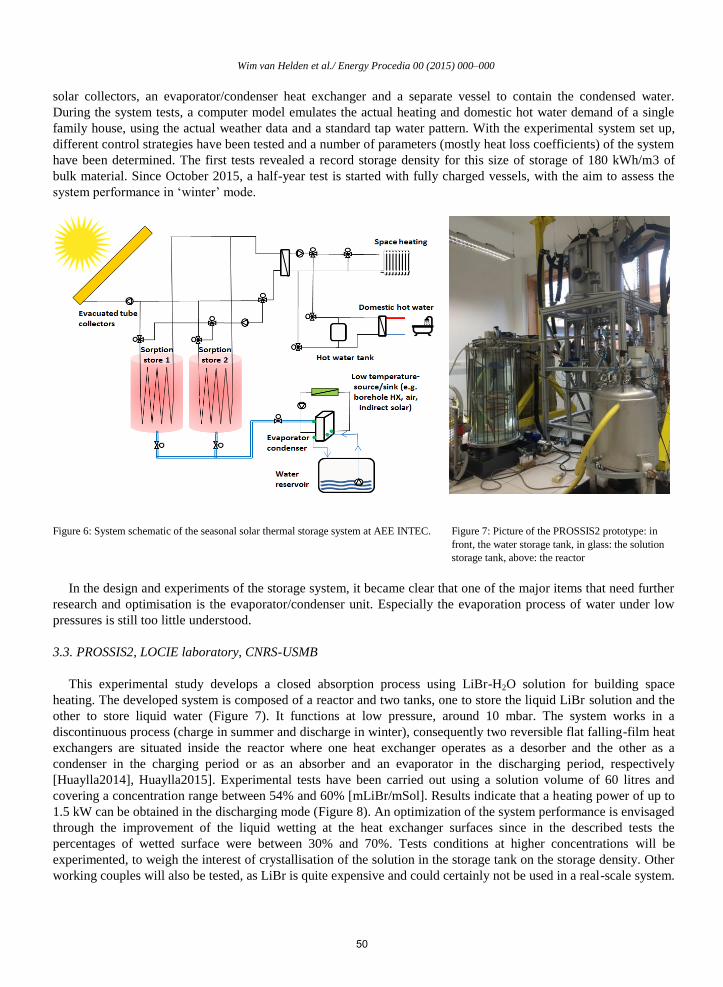
Wim van Helden et al./ Energy Procedia 00 (2015) 000–000
solar collectors, an evaporator/condenser heat exchanger and a separate vessel to contain the condensed water.
During the system tests, a computer model emulates the actual heating and domestic hot water demand of a single
family house, using the actual weather data and a standard tap water pattern. With the experimental system set up,
different control strategies have been tested and a number of parameters (mostly heat loss coefficients) of the system
have been determined. The first tests revealed a record storage density for this size of storage of 180 kWh/m3 of
bulk material. Since October 2015, a half-year test is started with fully charged vessels, with the aim to assess the
system performance in ‘winter’ mode.
Figure 6: System schematic of the seasonal solar thermal storage system at AEE INTEC. Figure 7: Picture of the PROSSIS2 prototype: in
front, the water storage tank, in glass: the solution
storage tank, above: the reactor
In the design and experiments of the storage system, it became clear that one of the major items that need further
research and optimisation is the evaporator/condenser unit. Especially the evaporation process of water under low
pressures is still too little understood.
3.3. PROSSIS2, LOCIE laboratory, CNRS-USMB
This experimental study develops a closed absorption process using LiBr-H2O solution for building space
heating. The developed system is composed of a reactor and two tanks, one to store the liquid LiBr solution and the
other to store liquid water (Figure 7). It functions at low pressure, around 10 mbar. The system works in a
discontinuous process (charge in summer and discharge in winter), consequently two reversible flat falling-film heat
exchangers are situated inside the reactor where one heat exchanger operates as a desorber and the other as a
condenser in the charging period or as an absorber and an evaporator in the discharging period, respectively
[Huaylla2014], Huaylla2015]. Experimental tests have been carried out using a solution volume of 60 litres and
covering a concentration range between 54% and 60% [mLiBr/mSol]. Results indicate that a heating power of up to
1.5 kW can be obtained in the discharging mode (Figure 8). An optimization of the system performance is envisaged
through the improvement of the liquid wetting at the heat exchanger surfaces since in the described tests the
percentages of wetted surface were between 30% and 70%. Tests conditions at higher concentrations will be
experimented, to weigh the interest of crystallisation of the solution in the storage tank on the storage density. Other
working couples will also be tested, as LiBr is quite expensive and could certainly not be used in a real-scale system.
50
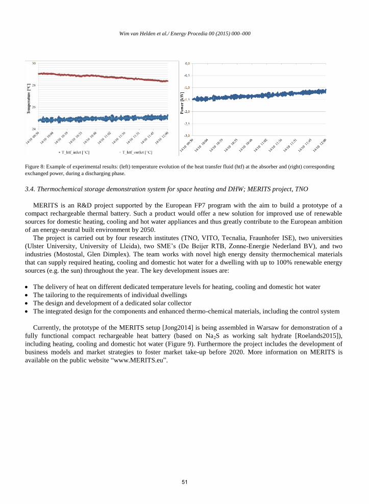
Wim van Helden et al./ Energy Procedia 00 (2015) 000–000
Figure 8: Example of experimental results: (left) temperature evolution of the heat transfer fluid (htf) at the absorber and (right) corresponding
exchanged power, during a discharging phase.
3.4. Thermochemical storage demonstration system for space heating and DHW; MERITS project, TNO
MERITS is an R&D project supported by the European FP7 program with the aim to build a prototype of a
compact rechargeable thermal battery. Such a product would offer a new solution for improved use of renewable
sources for domestic heating, cooling and hot water appliances and thus greatly contribute to the European ambition
of an energy-neutral built environment by 2050.
The project is carried out by four research institutes (TNO, VITO, Tecnalia, Fraunhofer ISE), two universities
(Ulster University, University of Lleida), two SME’s (De Beijer RTB, Zonne-Energie Nederland BV), and two
industries (Mostostal, Glen Dimplex). The team works with novel high energy density thermochemical materials
that can supply required heating, cooling and domestic hot water for a dwelling with up to 100% renewable energy
sources (e.g. the sun) throughout the year. The key development issues are:
The delivery of heat on different dedicated temperature levels for heating, cooling and domestic hot water
The tailoring to the requirements of individual dwellings
The design and development of a dedicated solar collector
The integrated design for the components and enhanced thermo-chemical materials, including the control system
Currently, the prototype of the MERITS setup [Jong2014] is being assembled in Warsaw for demonstration of a
fully functional compact rechargeable heat battery (based on Na2S as working salt hydrate [Roelands2015]),
including heating, cooling and domestic hot water (Figure 9). Furthermore the project includes the development of
business models and market strategies to foster market take-up before 2020. More information on MERITS is
available on the public website “www.MERITS.eu”.
51

Wim van Helden et al./ Energy Procedia 00 (2015) 000–000
Figure 9: MERITS system setup (left) and MERITS heat battery demonstrator container (right) at the University of Lleida
3.5. FlowTCS, ITW
A long term thermal storage based on an open sorption process with zeolite and salt impregnated zeolite has been
developed, set up and tested on a test rig. The sorption storage is characterized by an external reactor concept. A
separation is made between the reactor with approximately 30 l of zeolite storage material and the material storage
reservoir (in lab test: 200 l storage material volume). This concept enables a high flexibility concerning storage
capacity (defined by the size of the material storage reservoir) and thermal power (defined by the reactor operation).
The reactor (Figure 10) is designed as a quasi-continuous cross flow reactor. The storage material slowly flows
down through the reactor led by gravity. Via a rotary feeder, which controls the mass flow through the reactor, the
storage material is discharged. The air flows in cross flow to the material and transports the heat and water vapour
into or out of the reactor. During discharge of the sorption storage the heat released in the reactor is transported to
the heating system / buffer store via an air to water heat exchanger. For charging of the sorption storage the air is
heated up in the air to water heat exchanger. The heat is delivered by solar thermal collectors or any other heat
source. An air to air heat exchanger is integrated into the reactor unit for heat recovery.
Figure 10: Reactor unit of the sorption storage: discharging mode
The charge and discharge of the developed sorption storage has been investigated on a so called Hardware In the
Loop (HIL) test rig. The charge and discharge process was operated fully automatically (e.g. the control and
regulation of the material and air flow). Zeolite and salt impregnated zeolite beads have been used as storage
material. Different experiments have been conducted by varying the humidity of the air flow (5 g/kg ... 11 g g/kg)
52
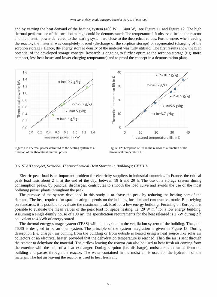
Wim van Helden et al./ Energy Procedia 00 (2015) 000–000
and by varying the heat demand of the heating system (400 W ... 1400 W), see Figure 11 and Figure 12. The high
thermal performance of the sorption storage could be demonstrated: The temperature lift observed inside the reactor
and the thermal power delivered to the heating system are close to the theoretical values. Furthermore, when leaving
the reactor, the material was completely loaded (discharge of the sorption storage) or regenerated (charging of the
sorption storage). Hence, the energy storage density of the material was fully utilised. The first results show the high
potential of the developed storage concept. Research is ongoing to further optimize the sorption storage (e.g. more
compact, less heat losses and lower charging temperature) and to proof the concept in a demonstration plant.
Figure 11: Thermal power delivered to the heating system as a
function of the theoretical thermal power
Figure 12: Temperature lift in the reactor as a function of the
theoretical temperature lift.
3.6. STAID project, Seasonal Thermochemical Heat Storage in Buildings; CETHIL
Electric peak load is an important problem for electricity suppliers in industrial countries. In France, the critical
peak load lasts about 2 h, at the end of the day, between 18 h and 20 h. The use of a storage system during
consumption peaks, by punctual discharges, contributes to smooth the load curve and avoids the use of the most
polluting power plants throughout the peak.
The purpose of the system developed in this study is to shave the peak by reducing the heating part of the
demand. The heat required for space heating depends on the building location and constructive mode. But, relying
on standards, it is possible to evaluate the maximum peak load for a low energy building. Focusing on Europe, it is
possible to evaluate the mean values of the peak load for space heating, i.e. 20 W m-2
for a low energy building.
Assuming a single-family house of 100 m2, the specification requirements for the heat released is 2 kW during 2 h
equivalent to 4 kWh of energy stored.
The thermal energy storage system (TESS) will be integrated in the ventilation system of the building. Thus, the
TESS is designed to be an open-system. The principle of the system integration is given in Figure 13. During
desorption (i.e. charge), air coming from the building or from outside is heated using a heat source like solar air
collectors or an electrical heater, provided that the dehydration temperature is reached. Then the air is sent through
the reactor to dehydrate the material. The airflow leaving the reactor can also be used to heat fresh air coming from
the exterior with the help of a heat exchanger. During sorption (i.e. discharge), moist air is extracted from the
building and passes through the reactor. The water contained in the moist air is used for the hydration of the
material. The hot air leaving the reactor is used to heat fresh air.
53

Wim van Helden et al./ Energy Procedia 00 (2015) 000–000
Figure 13: System integration with storage and release phases Figure 14: Picture of the experimental prototype
Zeolite is the material used in the reactor, 80kg. Dealing with the price criteria, Na-X has finally been selected
even if a lower heat of hydration than Na-Y (difference about 5%). The whole system consists of two sub-reactors
and ducts to drive the airflow into the reactors. The length of the reactors upstream and downstream ducts is ten
times their diameter in order to allow a correct measurement of the airflow. Of course an end user system should be
more compact. A picture of the reactor is given in Figure 14. Table 1 shows the experimental conditions during the
tests.
Table 1: Experimental conditions of the tests
Figure 15 shows the evolution of sensible power generated by the TESS according to the test cases. The serial
configuration (test 2) is reaching a higher maximum power than the equivalent parallel configuration (test 1). This
feature is due to the thermal mass of the second reactor requiring energy from the first one in serial configuration.
Hence, serial configuration is not suitable as the maximum power is not constant. Comparing tests 1 and 3, we can
observe that decreasing the dehydration temperature leads to decrease the energy but with the same sensible power:
duration of maximum is lower for test 3 than for test 1. The maximum power value is 2250 W. The comparison
between test 3 and 4 shows the influence of the relative humidity since for test 3 it has been set to 70 % while this
value is 50 % for test 4. Thus, the sensible power decreases to 1550 W and the hydration phase is about an hour
longer. The results from test 5 show the influence of decreasing the airflow rate to 120 m3 h
-1 both for hydration and
dehydration phases. Hence, the released energy is the same as test 1 but with a lower maximum power: 1500 W
against 2250 W. The hydration phase in this configuration lasts 9 h at the maximum power and decreases to 0 W
after 14 h.
The aim of this work was to develop and to characterize a zeolite thermal energy storage system to supply at least
2000 W sensible heating power during 2 h. The experimental results show that it is possible with the designed open
54

Wim van Helden et al./ Energy Procedia 00 (2015) 000–000
reactor, which provided 2250 W during 6 h, namely 27.5 W kg-1
of material. The reactor size can even be reduced to
really meet the requirement of 2 h.
Figure 15: Sensible power generated by the TESS Figure 16: Scheme of the ZAE Bayern thermochemical heat storage
using aqueous LiBr solution
3.7. Thermochemical heat storage using aqueous LiBr solution; ZAE Bayern
A thermochemical heat storage operating equivalent to an absorption heat pump, see Figure 16. Utilising solar
heat (simulated by a gas-fuelled boiler) to charge the storage (i.e. to concentrate the lithium bromide solution by
stripping water); during discharging, low temperature heat is used to evaporate the previously stripped water and the
vapor is absorbed into the solution, decreasing the concentration of salt and releasing heat which can be used for low
temperature heating. The charging power of the system is 6 kW, with charging/discharging temperatures of 70/30
°C; The storage has a total net volume of 0.5 m3 storage material, with 85 kWh storage capacity.
3.8. Long term heat storage with stable supercooled sodium acetate trihydrate; DTU
Sodium acetate trihydrate can be melted by solar energy in the summer. The melted salt can be cooled down to
ambient temperature in its liquid phase without solidifying. Utilizing this supercooling effect the heat storage has no
heat loss for a period when it rests at ambient temperature. When heat is needed solidification is started and the
temperature in the salt increases to the melting temperature of 58 °C. The heat can be discharged and utilized. Figure
17 illustrates the principle by means of the heat content of sodium acetate trihydrate in the temperature interval from
20°C to 90°C. Different heat storage modules have been tested, both in laboratory heat storage test facilities and as
part of a laboratory demonstration system consisting of 22.4 m² solar collectors, a PCM heat storage consisting of 4
modules as shown in Figure 18 and Figure 19 and a buffer tank [Dannemand2015a].
The main challenges of the concept are to achieve stable supercooling, reliable activation of solidification,
sufficiently high heat exchange capacity rates to and from the heat storage, high enough heat content of the heat
storage and long term stability of the heat storage with the high heat content [Dannemand2015b].
The ongoing test of the demonstration system will hopefully elucidate that the challenges have been tackled,
[Berg2015].
Based on the knowledge gained in the projects it is hopefully possible in the future to develop economically
attractive compact long term PCM heat storages.
55

Wim van Helden et al./ Energy Procedia 00 (2015) 000–000
Figure 17: Heat content of sodium acetate trihydrate in the temperature interval 20°C-90°C.
Figure 18: Sketch of PCM heat storage with four modules for the
demonstration system.
Figure 19: PCM heat storage with four modules for the demonstration
system.
3.9. PCM in building construction (radiant floor) or in HVAC systems; University of Zaragoza
The project has the aim to implement a thermal energy system (TES) with phase change materials (PCM) system
in several applications: the energetic optimization in buildings with the use of PCM in their construction, and the
study of the improvement of HVAC systems because of the use of PCM. For this purpose, adequate materials to the
studied applications have been searched, and their most important thermophysical properties have been evaluated.
All these data will improve the data base available within the research group. Later, the systems have been designed
and a prototype of some of them have been built. Simulation has been used as a tool to extrapolate the results to
other climates, applications, etc. Finally, an energetic and exergetic evaluation has been done to show the
contribution to the energy demand and to the reduction of the ambient impact, also an economic viability analysis
has been done. In the next steps, the life cycle analysis will be used to improve the systems.
The technical characteristics of one of the studied systems are: Storage capacity 6.8 kWh/per cycle; 132 kg of
PCM; 250 kg overall system mass. First applications foreseen are free cooling or temperature maintenance in rooms
(i.e. telecom shelters or similar)
56

Wim van Helden et al./ Energy Procedia 00 (2015) 000–000
During the project, several challenges came up: trade-off between material properties and system design is a
feature (a better designed heat exchange system but with worse PCM -in terms of melting enthalpy and thermal
conductivity-, can lead to better thermal performance). To turn some of the PCM based TES solutions more
economically feasible, finding low cost PCM can be an issue. Further details can be found in [Lazaro2009],
[Dolado2011] and [Mazo2012].
3.10. Under floor PCM for residential heating; Chubu University
PCM containers are installed under the floor of a residential house, see Figure 21. The system will take advantage
of the electricity tariff difference between day and night [Lun2015]. The phase change material applied is paraffin
wax with 25 °C melting temperature. The material is packed in a container of 300 x 300 x 20 mm and is installed in
wooden boxes. 90 containers which contain 90 kg of PCM in total were connected in series under the floor of the
house. During night time when discount tariff is offered, an air conditioner is in operation, charging the PCM
containers. From 7:00 in the morning, a fan is turned on to circulate the air through the house for discharging.
Demonstration houses are built in Nagano city and Aichi prefecture in Japan.
Figure 20: Experimental setup to test real scale PCM-Air TES systems. Figure 21: Schematic of the underfloor PCM storage system
3.11. Compact latent heat TES for micro-cogeneration plants; University of the Basque Country
The aim of the project is to develop a modular latent heat thermal energy storage system based on plates for its
integration within micro-cogeneration (micro-CHP) plants. The plates are made of hollow aluminium filled with
PCM. The HTF (water) flows in laminar regime through the spaces between the parallel plates exchanging heat with
the PCM by the plate surfaces. The plates are grouped in stacks as it can be seen in Figure 22. The modular nature of
the stacks of plates makes the solution very suitable for applications with different constraints, such as volume,
capacity, power, maximum admissible discharging time, etc. The solution can be also integrated in other intermittent
applications, for example thermal solar, waste heat, etc.
Figure 23 represents the integration of the latent heat TES system within the micro-CHP plant. It is placed in
series at the return from the consumption (space heating and domestic hot water DHW). Thus, the system stores the
surplus heat that is not consumed by the user, storing at full load at those moments with the micro-CHP operating
with no demand. It can be seen that the domestic hot water (DHW) production has priority over the heating load,
being produced by a plate heat exchanger. More information about the latent heat TES system and the integration
into micro-CHP plants can be found in [Campos-Celador2013] and [Campos-Celador2014].
RT60 PCM by Rubitherm GmbH was selected as the latent storage medium with a phase change around 60ºC.
The design parameters are the following: 4.1 kW charging (at 65ºC), 3.4 kW discharging (at 50ºC); and 0.3 m3
volume with about 7.2 kWh capacity. Though experiments have been done at laboratory scale, the full scale LHTES
57

Wim van Helden et al./ Energy Procedia 00 (2015) 000–000
prototype is currently under construction. The plate based latent heat TES system prototype will be included in a
micro-CHP plant and tested under real operation conditions.
Figure 22: Schematic view of a stack consisting of 12
plates (6 in parallel and 2 in series)
Figure 23: Schematic view of the latent heat TES integration within the micro-CHP
installation
4. Storage applications for industry
4.1. Mobile sorption heat storage for industrial waste heat recovery, ZAE Bayern
A zeolite sorption storage, mounted on a semi-trailer, is charged using heat from a waste incineration plant, and
driven to an industrial drying process in about 8 km distance, where the heat is released, substituting natural gas.
The storage is charged by applying a hot airstream to the system, thus drying the zeolite. Discharging mode requires
a moist airstream, which is dried and heated up by passing through the packed bed of zeolite. The operation
conditions determine the water content of the zeolite at the charging and discharging cycle, which are important
parameters for the energy capacity of the storage. Low invest costs, a short distance between charging and
discharging station, a high energy capacity of the storage, and a customer with an almost constant annual heat
demand are required to operate a mobile sorption storage system competitively [Kronauer].
The input temperatures to the storage are 250 °C and 60 °C for charging and discharging, respectively. A peak
power of 300 kW can be provided for about 8 hours during discharging. Each storage container contains 22 m³ of
heat storage material. The storage capacity under the given reference conditions is 4,600 kWh per container.
4.2. Development of macro-encapsulated latent heat storage for the transport of heat, University of Bayreuth
The latent thermal energy storage system is designed for mobile applications. It consists of a 20 feet long ISO
container that is transportable with motor trucks.
Table 2: Key parameters of the previous storage container
Inlet temperature (charging/discharging) 90 / 40 °C
Discharging power (final/initial) 50 / 350 kW
Storage capacity (between 40 and 90 °C) 2300 kWh
Based on an already existing design with the key parameters shown in Table 22, an improved storage unit is
evolved. For a considerably higher charging and discharging power the heat exchanger surface is increased by
macro encapsulation see Figure 25. The range of applications of this mobile latent heat storage device is highly
expanded by applying PCM with melting temperatures between 70 °C and 150 °C and the utilization of thermally
stable metallic encapsulation materials [Hohlein2016]. Heat sources are for instance industrial waste heat. The
58

Wim van Helden et al./ Energy Procedia 00 (2015) 000–000
previous storage system based on sodium acetate tri-hydrate with its low melting point of 58 °C is suitable only for
the supply of few specific heat sinks, e.g. for heating swimming pool water. The new system will be able to provide
heat at a temperature level suitable for process heat applications.
Figure 24: Principle of mobile sorption heat storage in industrial waste heat recovery Figure 25: Macroscopic encapsulated PCM for
mobile latent thermal energy storage of University of
Bayreuth
5. Conclusions
One of the main elements in the work of T4229 was the further development of system applications for compact
thermal energy storage in three temperature fields: low temperatures for cooling, medium temperatures for room
heating and domestic hot water and high temperatures for industry. A large number of groups worked on these
applications and their work provided inputs for validation of numerical models and boundary conditions for the
further and more targeted development of materials.
Considerable progress was made on a broad range in the development of components and systems, providing
knowledge and experience regarding the design, numerical modeling, building, testing and economical assessing of
components and storage systems. The vast amount of knowledge and experience that was gained by the different
projects, lead to the following conclusions.
The interaction between the storage materials and the materials of the system components can be deciding for the
technical feasibility of the combination. Therefore, more targeted development of components should be done in
combination with the storage material.
A number of components appeared to be less understood than initially thought. This concerns especially reactors,
heat exchangers and evaporators for water under low pressure. These components need targeted attention for further
research and development.
The inclusion of storage materials in components or systems generate new challenges like the occurrence of non-
condensable gases and thermomechanical effects. To circumvent or prevent these, novel technologies have to be
sought and applied in the components design.
Especially for thermochemical technologies, new technologies to determine the state of charge of the storage
need to be developed.
In order to obtain a better comparison between system performance of different technologies, more standardized
and simplified system approaches are needed.
Additionally, long term testing under real operating conditions (high level integration) will be fundamental for
the implementation of novel TES approaches. This will have to assess the interaction between the TES system and
the rest of the components through the lifespan of the whole application.
59
Wim van Helden et al./ Energy Procedia 00 (2015) 000–000
And in general, the development of all components and system configurations should be more aimed at cost
reduction of the final system.
Acknowledgements
The financial supports of the European Commission for subsidizing the COMTES project within the 7th
framework program for research is acknowledged.
The University of Bayreuth sincerely thanks the Federal Ministry of Economic Affairs and Energy (BMWi),
Germany for the research funding and support.
The work of ZAE Bayern was supported by the German Federal Ministry for Economic Affairs and Energy
(BMWi) under the project code 0327383B, and by the Federal Ministry for the Environment, Nature Conservation
and Nuclear Safety (BMU) under the project codes 0329605O and 0325978A.
The university of Zaragoza thanks the Spanish Government for the partial funding of this work within the
framework of research projects ENE2008-06687-C02-02, ENE2011-28269-C03-01 and ENE2014-57262-R. Special
thanks are extended to Miguel Zamora, CIAT R&D Manager, for his collaboration.
The LOCIE laboratory thanks the ANR (French National Research Agency) for its financial support under the
research projects PROSSIS2 ANR-11-SEED-0011-01.
The University of the Basque Country acknowledges the financial support of the Spanish Ministry of Economy
and Competitiveness through the MicroTES (ENE2012-38633) research project.
The research leading to the results of MERITS has received funding from the European Commission Seventh
Framework Programme (FP/2007-2013) under grant agreement No ENER/FP7/295983 (MERITS).
References
[Berg2015] J. Berg Johansen, M. Dannemand, W. Kong, G. Englmair, J. Fan, J. Dragsted, B. Perers, S. Furbo. Practical application of compact
long term heat storage. Laboratory testing of solar combi system with compact long term PCM heat storage. SHC Conference 2015, Istanbul
Turkey.
[Campos-Celador2013] Campos-Celador A, Diarce G, González-Pino I, Sala JM. Development and comparative analysis of the modelling of an innovative finned plate latent heat thermal energy storage system. Energy 2013; 58: 438-447.
[Campos-Celador2014] Campos-Celador A, González-Pino I, Bandos TV. Simulation of a latent heat thermal storage system within a Stirling based micro-CHP residential installation. Proceedings of the 16th ISEC International Stirling Engine Conference (Bilbao) 2014.
[Daguenet-Frick2015] X. Daguenet-Frick, P. Gantenbein, E. Frank, B. Fumey, R. Weber, T. Williamson. Development of a numerical model for the reaction zone design of an aqueous sodium hydroxide seasonal thermal energy storage. Solar Energy, ISES Solar World Congress 2013
(SWC2013) Special Issue 121, 17–30. doi:10.1016/j.solener.2015.06.009
[Dannemand2015a] M. Dannemand, W. Kong, J. Fan, J.B. Johansen, S. Furbo, Laboratory Test of a Prototype Heat Storage Module Based on
Stable Supercooling of Sodium Acetate Trihydrate, in: Energy Procedia, Elsevier B.V., 2015: pp. 172–181. doi:10.1016/j.egypro.2015.02.113.
[Dannemand2015b] M. Dannemand, J.M. Schultz, J.B. Johansen, S. Furbo, Long term thermal energy storage with stable supercooled sodium
acetate trihydrate, Appl. Therm. Eng. 91 (2015) 671–678. doi:10.1016/j.applthermaleng.2015.08.055.
[Dolado2011] P. Dolado, A. Lázaro, J.M. Marín, B. Zalba. “Characterization of melting and solidification in a real scale PCM-air heat exchanger:
Experimental results and empirical model”, Renewable Energy, Volume 36, Issue 11, November 2011, Pages 2906-2917. DOI:
10.1016/j.renene.2011.04.008
[Fumey2013] B. Fumey, R, Weber, P, Gantenbein, X, Daguenet-Frick, T, Williamson, V, Dorer,, Closed sorption heat storage based on aqueous
sodium hydroxide, SHC2013 Germany, Energy Procedia 48 (2014) 337 – 346
[Fumey2015] B. Fumey; R. Weber; P. Gantenbein; X. Daguenet-Frick; Sascha Stoller; Reto Fricker; V. Dorer, Operation results of a closed
sorption heat storage prototype, IRES2015, Germany. Energy Procedia 73 (2015) 324 – 330
[Hauer2015] Andreas Hauer, The 4-temperature approach – A method to evaluate new materials for thermochemical heat storage under
application conditions.
[Helm2014] M. Helm, K. Hagel, W. Pfeffer, S. Hiebler, C. Schweigler, Solar Heating and Cooling System with Absorption Chiller and Latent
Heat Storage – A Research Project Summary, Energy Procedia 48 (2014) 837-849
60

Wim van Helden et al./ Energy Procedia 00 (2015) 000–000
[Hohlein2016] S. Höhlein, A. König-Haagen, D. Brüggemann: "EXPERIMENTAL INVESTIGATION ON PHASE CHANGE MATERIALS
(PCM) FOR MOBILE HEAT STORAGE DEVICES"; Poster session presented at: 10th International Renewable Energy Storage Conference
(IRES 2016), 2016 March 15-17; Düsseldorf, Germany.
[Huaylla2014] Huaylla F., Le Pierrès N., Stutz B., Performance analysis of multifunctional exchangers implemented in an interseasonal sorption
heat storage system, ISHPC (International Sorption Heat Pump Conference), Maryland (USA), March 31- April 3 2014
[Huaylla2015] Huaylla F., Le Pierrès N., Stutz B., Numerical and experimental analysis of an absorption reactor using LiBr/H2O for solar heat
long-term storage, ECCE10 (10th European Congress of Chemical Engineering), Nice (France), September 27-October 1 2015
[Jong2014] Jong Aj de, Finck C, Oversloot H, Spijker H van ‘t, Cuypers R, Thermochemical heat storage (TCS) - system design issues, Energy
Procedia 2014; 48: 309 – 319.
[Kronauer] A. Krönauer, E. Lävemann, S. Brückner, M. Gaaß, M. Treder, B. Kinzel, A. Hauer, Mobile Sorptionsspeicher zur industriellen Abwärmenutzung, Grundlagen und Demonstrationsanlage (MobS II), final report, available from: http://www.tib.uni-hannover.de/en.html
[Lazaro2009] A. Lázaro, P. Dolado, J.M. Marín, B. Zalba. PCM-air heat exchangers for free-cooling applications in buildings: Experimental results of two real-scale prototypes. Energy Conversion and Management, Volume 50, Issue 3, March 2009, Pages 439-443.
[Lun2015] Lun wan, Motoi Yamaha, Hideki Takamura and Aya Yokoe, A study on thermal characteristics of a latent heat storage tank placed under floor of a residential house Part 1: Measurement of Phase Change Material and Thermal Response of a Tank, Greenstock 2015, 13th
international conference on thermal energy storage, 2015
[Mazo2012] J. Mazo, M. Delgado, J. M. Marin, B. Zalba. “Modeling a radiant floor system with Phase Change Material (PCM) integrated into a
building simulation tool: Analysis of a case study of a floor heating system coupled to a heat pump”, Energy and Buildings, Volume 47, April
2012, Pages 458-466. DOI:10.1016/j.enbuild.2011.12.022
[Roelands2015] Roelands M, Cuypers R, Kruit K, Oversloot H, Jong AJ de, Spijker H van ‘t, Duvalois W, Vliet L van, Hoegaerts C, Preparation
& characterization of sodium sulfide hydrates for application in thermochemical storage systems, Energy Procedia 2015; 70: 257 – 266.
61

Available online at www.sciencedirect.com
ScienceDirect
Energy Procedia 00 (2015) 000–000
www.elsevier.com/locate/procedia
1876-6102 © 2015 The Authors. Published by Elsevier Ltd.
Peer-review by the scientific conference committee of SHC 2015 under responsibility of PSE AG.
SHC 2015, International Conference on Solar Heating and Cooling for Buildings and Industry
IEA SHC Task 42 / ECES Annex 29 – A simple tool for the
economic evaluation of thermal energy storages
Christoph Rathgeber a,*, Stefan Hiebler
a, Eberhard Lävemann
a, Pablo Dolado
b,
Ana Lazaro b, Jaume Gasia
c, Alvaro de Gracia
c, Laia Miró
c, Luisa F. Cabeza
c,
Andreas König-Haagen d, Dieter Brüggemann
d, Álvaro Campos-Celador
e,
Erwin Franquet f, Benjamin Fumey
g, Mark Dannemand
h, Thomas Badenhop
i,
Jan Diriken j,k
, Jan Erik Nielsen l, Andreas Hauer
a
a Bavarian Center for Applied Energy Research (ZAE Bayern), Walther-Meißner-Str. 6, 85748 Garching, Germany b I3A – Univ, of Zaragoza, Spain; c GREA Innovació Concurrent, Univ. of Lleida, Spain; d Univ. of Bayreuth, LTTT, Germany; e
Univ. of the Basque Country UPV-EHU, Spain; f LaTEP-ENSGTI, Univ. Pau & Pays Adour, France; g Empa, Switzerland; h Technical Univ. of Denmark DTU; i Vaillant GmbH, Germany;
j Flemish Institute for Technological Research (VITO), Belgium; k Energyville, Belgium; l PlanEnergi, Denmark
Abstract
Within the framework of IEA SHC Task 42 / ECES Annex 29, a simple tool for the economic evaluation of thermal energy
storages has been developed and tested on various existing storages. On that account, the storage capacity costs (costs per
installed storage capacity) of thermal energy storages have been evaluated via a Top-down and a Bottom-up approach. The Top-
down approach follows the assumption that the costs of energy supplied by the storage should not exceed the costs of energy
from the market. The maximum acceptable storage capacity costs depend on the interest rate assigned to the capital costs, the
intended payback period of the user class (e.g. industry or building), the reference energy costs, and the annual number of storage
cycles. The Bottom-up approach focuses on the realised storage capacity costs of existing storages. The economic evaluation via
Top-down and Bottom-up approach is a valuable tool to make a rough estimate of the economic viability of an energy storage for
a specific application. An important finding is that the annual number of storage cycles has the largest influence on the cost
effectiveness. At present and with respect to the investigated storages, seasonal heat storage is only economical via large sensible
hot water storages. Contrary, if the annual number of storage cycles is sufficiently high, all thermal energy storage technologies
can become competitive.
© 2015 The Authors. Published by Elsevier Ltd.
* Corresponding author. Tel.: +49 89 329 442 88; fax: +49 89 329 442 12.
E-mail address: [email protected]
62

Christoph Rathgeber / Energy Procedia 00 (2015) 000–000
Peer-review by the scientific conference committee of SHC 2015 under responsibility of PSE AG.
Keywords: Sensible heat storage; Latent heat storage; Thermochemical heat storage; Storage capacity costs
1. Introduction
Heat and cold storage are key technologies for increasing energy efficiency and a more extensive utilisation of
renewable energy sources. A major barrier to the development of thermal energy storage (TES) technologies is cost
uncertainty [1]. In order to make a rough estimate of the economic viability of an energy storage for a specific
application, a simple tool was developed, which consists in determining the maximum acceptable storage capacity
costs via a Top-down approach and the realised storage capacity costs via a Bottom-up approach.
Nomenclature
ANF annuity factor / a-1
i interest rate
INC investment costs / €
n payback period / a
Ncycle number of storage cycles per year / a-1
REC reference energy costs / €∙kWhen-1
SC storage capacity / kWhcap
SCCacc maximum acceptable storage capacity costs / €∙kWhcap-1
SCCreal realised storage capacity costs / €∙kWhcap-1
2. Methods
2.1. Top-down approach
The Top-down approach assumes that the cost of energy supplied by the storage should not exceed the costs of
energy from the market † (hereinafter referred to as REC = reference energy costs). Following this assumption, the
maximum acceptable storage capacity costs (hereinafter referred to as SCCacc) are calculated from the discount rate
of storage capital i, the payback period of the investment n, the number of storage cycles Ncycle, and the reference
energy costs [2]. To simplify the evaluation, this analysis neglects operating costs and changes in the cost of energy
production over time. Detailed information about the storage technology or implementation are not required for this
approach.
Using the interest rate assigned to the capital costs and the payback period, the present value annuity factor ANF
can be calculated to determine the present value of the energy storage capital. ANF as a function of payback period n
and interest rate i can be calculated via Eq. (1):
1)1(
)1(
n
n
i
iiANF (1)
Interest rate i and payback period n depend on the user. Three classes of users are referred to in the following
discussion. In the industry sector, high interest rates of 10% and above and short payback periods of 5 years and
below are usual. For building applications, moderate interest rates of 5% and longer payback periods of 15 – 20
† Communicated e.g. by Dr. Rainer Tamme, German Aerospace Center (DLR), in many presentations since 20 years.
63

Christoph Rathgeber / Energy Procedia 00 (2015) 000–000
years are acceptable. In addition, one might also assume a user that can tolerate even longer payback periods of 25
years and low interest rates of 1%. The latter user class has probably political or ecological reasons for the
investment and is hereinafter referred to as enthusiast. In Figure 1, the annuity factor ANF is plotted as a function of
the payback period n for interest rates of 10% (red solid line) indicating industry, 5% (blue dashed line) indicating
building, and 1% (green dotted line) indicating enthusiast.
Figure 1. Annuity factor ANF as a function of payback period n for three user classes (industry i = 10%, building i = 5%, and enthusiast
i = 1%); framed regions indicate acceptable annuity factors for these user classes.
In the industry sector, a payback period of 5 years yields an ANF of about 0.26. Therefore, a range of ANF from
0.25 to 0.30 is considered as storage capacity cost annuity for industrial users. In the building sector, ANF are within
0.07 – 0.10, and in the case of enthusiasts, consequently, low ANF between 0.04 and 0.06 can be achieved.
The maximum acceptable storage capacity costs SCCacc, calculated in € per kWh installed storage capacity
(€∙kWhcap-1
), are simply the product of the substituted reference energy costs REC, given in € per kWh energy
(€∙kWhen-1
), and the number of storage cycles per year Ncycle divided by the annuity factor ANF:
ANF
NRECSCC
cycleacc
(2)
Eq. (2) neglects operating costs and changes of REC over the payback period. Nevertheless, this analysis
illustrates the relationship between acceptable storage capacity costs, the frequency of storage handling, and the
costs of reference energy that is substituted by the storage system. Similar to ANF, a range is considered for REC. As the focus of this work is to evaluate the costs of thermal
energy storages, REC given in Table 1 correspond to heat or cold supply costs. Table 1 summarises the economic
boundary conditions of the three user classes that are taken into account in the Top-down evaluation.
Table 1. Economic boundary conditions: costs of substituted reference energy REC and storage annuity factor ANF calculated via Eq. (1).
User class REC / €∙kWhen-1 ANF / a-1
Industry 0.02 0.04 0.25 0.30
Building 0.06 0.10 0.07 0.10
Enthusiast 0.12 0.16 0.04 0.06
As an aid to orientation, expectable ranges for the costs of substituted reference energy REC and the storage
annuity factor ANF are considered. In this way, a high and a low cost case are analysed for each user class. The high
64

Christoph Rathgeber / Energy Procedia 00 (2015) 000–000
case considers the max. REC and the min. ANF, and the low case the min. REC and the max. ANF, respectively.
Future changes of the reference energy costs REC can be taken into account by adjusting the values of REC given in
Table 1 appropriately, e.g. by considering average REC for the intended payback period. According to Eq. (2),
SCCacc is proportional to REC and, hence, an increase in REC will cause a similar increase in SCCacc. Operating
costs should be taken into consideration if they are not negligible compared to the capital costs. Especially in the
case of mobile storages, operating costs are expected to have a significant influence on the economic viability. To
consider operating costs requires a modification of the Top-down approach. According to the procedure outlined
above, the Top-down approach calculates the costs per storage capacity. However, if operating costs have to be
included, the costs per stored energy have to be determined, for instance on an annual basis.
2.2. Bottom-up approach
The Bottom-up approach focuses on the realised storage capacity costs of existing storage systems (hereinafter
referred to as SCCreal). To investigate particular storages, a questionary was developed which inquires among other
technical parameters both actual and expectable investment costs INC of the storage divided into costs of the heat
storage material, costs of the storage container or reactor, and costs of the charging/discharging unit. For the
Bottom-up approach, sensible heat storage, latent heat storage via PCM, and thermochemical heat storage including
sorption storage have been investigated. Besides commercially available storage systems, innovative prototypes
which are subject of ongoing research have been analysed [3]. The realised storage capacity costs SCCreal are simply
the investment costs INC divided by the installed storage capacity SC:
SC
INCSCCreal (3)
INC sums up heat storage material costs, storage container or reactor costs, and cost of charging and discharging
device. As in the case of SCCacc, SCCreal are calculated in € per kWh installed storage capacity (€∙kWhcap-1
).
3. Results
The maximum acceptable storage capacity costs SCCacc for the three user classes calculated via Eq. (2) are
plotted as a function of the annual number of storage cycles Ncycle in Figure 2.
Figure 2. Maximum acceptable storage capacity costs SCCacc for three user classes as a function of storage cycles per year Ncycle; enthusiast
high/low case (green solid/dashed line), building high/low case (blue solid/dashed line), and industry high/low case (red solid/dashed line).
Solid lines indicate the high case of each user class and dashed lines the low case, respectively. A double-
65

Christoph Rathgeber / Energy Procedia 00 (2015) 000–000
logarithmic scale was chosen to visualize both SCCacc of long-term storages with only few cycles per year and short-
term storages with several hundred cycles per year. The results of the Top-down evaluation as shown in Figure 2
indicate that, for a fixed cycle period Ncycle, SCCacc depend on the user’s economic environment. The low case of the
industry sector and the high case of enthusiasts differ by a factor of about 60 in costs. Short-term storage with
several hundred storage cycles per year, however, allows several hundred times higher storage costs because of the
larger energy turnover.
For reasons of clarity, the comparison of SCCacc (Top-down approach) with SCCreal (Bottom-up approach) is split
up into four figures: long-term storages (Figure 3), hot-water storages up to 30 m³ storage volume (Figure 4), and
short-term storages (Figure 5 and 6). Relevant specifications of the investigated storage systems are listed in
Table 2.
Figure 3. Maximum acceptable storage capacity costs (SCCacc) and realised storage capacity costs (SCCreal) for long-term storages.
Seasonal TES with max. 2 cycles per year requires storage capacity costs below 3 €∙kWhcap-1
in the building and
below 0.4 €∙kWhcap-1
in the industry sector, respectively. With respect to the storages under investigation, seasonal
TES is only economical via large sensible hot water storages (cf. systems 3 – 7, Figure 3).
Figure 4. Maximum acceptable storage capacity costs (SCCacc) and realised storage capacity costs (SCCreal) for hot water storages up to 30 m3
storage volume.
In the case of hot-water storages up to 30 m³ storage volume, the building sector is usually targeted. However,
these storage can become financially attractive for industrial applications if Ncycle is sufficiently high. Since these
66

Christoph Rathgeber / Energy Procedia 00 (2015) 000–000
storages can be integrated in a variety of systems, exemplary ranges are indicated for Ncycle. The storage capacity SC
of the storages 9 – 13 is calculated for the maximum technically permissible temperature ranges indicated in
Table 2. To evaluate the economics under application conditions, these temperature ranges have to be adjusted.
On the other hand, in the case of short-term storages, storage systems are intended for either industry or building.
Among the investigated short-term storages, systems 14 – 17 and 18 – 26 have been developed for industry and
building applications, respectively.
Figure 5. Maximum acceptable storage capacity costs (SCCacc) and realised storage capacity costs (SCCreal) for industrial short-term storages.
Considering the investigated short-term storages for industrial applications (cf. Figure 5) it turns out that ice
storages (system 14) are cost-effective, and other technologies are within reach.
Figure 6. Maximum acceptable storage capacity costs (SCCacc) and realised storage capacity costs (SCCreal) for short-term storages in buildings.
In the case of the systems 1, 8, 14, 15, 18, 20, 22, 23 and 26, cost ranges are given for SCCreal indicating the
interval between actual costs (upper limit) and expectable costs that can be achieved in the near future (lower limit).
The mobile PCM storage (system 15) is intended to be operated for 100 – 200 cycles per year with a storage
capacity between 1,500 and 2,500 kWh depending on the degree of optimisation.
INC of the large water storages 2-7 are DMC (direct material costs) of the installed systems. INC of the
commercial water storages 9-13 are list prices [4]. In the case of the other investigated systems, INC correspond to
DMC of prototypes or estimated DMC and, therefore, numbers are roughly rounded. In addition, most of these
prototypes are subject of ongoing research and, hence, at a lower TRL with higher investment costs.
67

Christoph Rathgeber / Energy Procedia 00 (2015) 000–000
Table 2. Specifications of thermal energy storages investigated via Bottom-up approach: annual number of storage cycles Ncycle,
investment costs INC, installed storage capacity SC, realised storage capacity costs SCCreal.
Storage system (Institution) Description Ncycle /
a-1 INC /
€ SC /
kWhcap SCCreal /
€∙kWhcap-1
1: NaOH storage
(Empa)
NaOH sorption; seasonal storage for
domestic applications 1
8,000 –
32,400 2,500 3.2 – 13.0
2: Ottrupgård, 1995
(PlanEnergi)
Hot water; 1,500 m³;
35 – 60 °C 1 225,500 43,500 5.18
3: Sunstore 2, 2003
(PlanEnergi)
Hot water; 10,000 m³;
35 – 90 °C 1 671,100 638,000 1.05
4: Sunstore 3, 2013
(PlanEnergi)
Hot water; 60,000 m³;
10 – 90 °C 1 2,671,100 6,960,000 0.38
5: Sunstore 4, 2012
(PlanEnergi)
Hot water; 75,000 m³;
10 – 90 °C 1 2,281,900 5,570,000 0.41
6: Ackermannbogen
(ZAE Bayern)
Hot water; 6,000 m³;
20 – 90 °C 1.6 942,400 472,400 1.99
7: Attenkirchen
(ZAE Bayern)
Hot water + borehole heat exchanger;
7,000 m³; 10 – 90 °C 1.7 327,300 654,600 0.50
8: SAT storage [5, 6]
(DTU, Univ. Graz)
Supercooled sodium acetate trihydrate,
seasonal storage modular system 1 – 10
2,700 –
4,120 13 – 26 104 – 317
9: VSI – 30 m³ (ZAE Bayern,
Hummelsberger GmbH)
Vacuum super insulated hot water
storage; 30 m³; 5 – 95 °C 5 – 10 a 37,888 3,020 12.5
10: allSTOR VPS/3 2000/3-7
(Vaillant GmbH)
Hot water; 2,000 l;
5 – 95 °C
5 –
100 a 3,559 202 17.6
11: VSI – 5 m³ (ZAE Bayern,
Hummelsberger GmbH)
Vacuum super insulated hot water
storage; 5 m³; 5 – 95 °C
20 –
30 a 15,962 504 31.7
12: actoSTOR VIH RL 500-60
(Vaillant GmbH)
Hot water; 500 l;
5 – 110 °C
10 –
300 a 4,953 58.7 84.4
13: actoSTOR VIH CL 20 S
(Vaillant GmbH)
Potable water; 20 l;
10 – 70 °C
100 –
2000 a 965 1.35 715
14: Ice storages
(Cristopia)
Storages with nodules filled with
water/ice; installations in Europe
120 –
150 - - 20 – 25
15: NaOAc mobile storage
(Univ. Bayreuth, LaTherm)
Mobile PCM storage (sodium acetate
trihydrate); 40 – 90 °C
100 –
200 99,000
1,500 –
2,500 39.6 – 66.0
16: Dual media storage
(ZAE Bayern, Gießerei Heunisch)
Sensible storage; stone + heat transfer
oil; up to 300 °C 200 400,000 6,500 61.5
17: MobS
(ZAE Bayern)
Mobile sorption heat storage (2x14 t
zeolite); industrial waste heat recovery 240 440,000 9,200 47.8
18: SolarHeatCool+PCM
(ZAE Bayern)
1 m³ PCM storage (CaCl2∙6H2O);
22 – 36 °C 200
4,700 –
6,300 83 56.6 – 75.9
19: TubeICE
(VITO)
Modular PCM tubes (Salt hydrate +
graphite); 30 – 70 °C 200 900 13 69.2
20: Dishwasher
(ZAE Bayern)
Dishwasher with sorption drying
(1.5 kg zeolite) 250 29 – 38 0.3 96.7 – 127
21: RT58 storage
(VITO)
0.2 m³ PCM storage (RT58); 30 –
70 °C 200 1,850 6 308
68

Christoph Rathgeber / Energy Procedia 00 (2015) 000–000
22: LiBr storage
(ZAE Bayern)
Sorption storage (aqueous LiBr
solution); domestic applications 250
31,000 –
47,000 85 365 – 553
23: PCM-Air [7, 8]
(Univ. Zaragoza)
Free-cooling; PCM-Air heat
exchanger; RT27 as PCM 30
2,000 –
3,900 6.8 294 – 574
24: VDSF
(Univ. Lleida)
Free cooling; ventilated double skin
facade + PCM (SP21) 240 5,133 7 733
25: Hydroquinone storage
(Univ. Lleida)
Solar applications; hydroquinone as
PCM; 145 – 187 °C 240 16,768 13.7 1,223
26: RT60 storage [9] (Univ. Basque Country UPV-EHU)
Plate based PCM storage (RT60) for a domestic micro-CHP installation
330 5,500 – 6,000
7.2 764 – 833
a storages can be integrated in a variety of systems with different Ncycle
In order to identify major cost drivers and cost reduction potentials for the investigated storages, the composition
of the investment costs INC has been analysed. Figure 7 illustrates how INC of the thermal energy storages under
investigation are divided into costs of the heat storage material itself and costs of the surrounding container or
reactor incl. charging/discharging device. If available, both actual (a) and expectable (b) costs are given.
Figure 7. Actual (a) and expectable (b) Investment costs INC of the thermal energy storages under investigation divided into costs of the heat
storage material and costs of the container incl. charging/discharging device.
In the majority of cases, the costs of the container incl. charging/discharging device exceed the costs of the heat
storage material by far. For 9 out of 13 investigated storages, the costs of the heat storage material account for 25%
or less of the total INC. Just in one case, the costs of the heat storage material account for more than 50% of INC.
The composition of both actual and expectable investment costs indicates the significant potential to reduce storage
costs by developing cost-effective storage containers and charging/discharging devices.
0% 10% 20% 30% 40% 50% 60% 70% 80% 90% 100%
(b) 26. (a)
25.
24.
(b) 23.(a)
(b) 22.(a)
21.
(b) 20.(a)
19.
(b) 18.(a)
(b) 17.(a)
16.
15.
(b) 1.(a)
heat storage material container incl. charging/discharging device
69

Christoph Rathgeber / Energy Procedia 00 (2015) 000–000
4. Discussion
The Top-down approach indicates some important findings in thermal energy storage economics that have often
been ignored. First, for a fixed storage period, the maximum acceptable storage costs depend on the user’s economic
environment (e.g. industry or building) due to variances in payback period, discount rate, and costs of reference
energy from the market. Second, the annual number of storage cycles has by far the largest influence on the
maximum acceptable storage capacity costs and the cost effectiveness of storages. Third, scenarios exist under
which most storage technologies are economical. In this case, systems should be compared with regard to physical
and technical attributes.
The Bottom-up approach has been applied to analyse the costs of 26 thermal energy storages. Contrary to
commercial water storages, several innovative storages are subject of ongoing research and, hence, their
corresponding costs are roughly estimated. The comparison of SCCacc and SCCreal indicates that, at present, seasonal
storage is only economical using large hot water storages; other technologies require at least an order of magnitude
reduction in costs. That implies that the development of storage systems which allow a high annual number of
storage cycles is economically favourable over seasonal storages with exactly one cycle per year. In addition, the
Bottom-up analysis showed that a major fraction of the investment costs of the investigated storages are not costs of
the heat storage material itself but costs of the storage container or reactor incl. charging/discharging unit.
Therefore, R&D activities on cost-effective TES systems have to consider both cost-effective heat storage materials
and cost-effective storage container or reactor components.
The economic evaluation via Top-down and Bottom-up approach is not limited to thermal energy storage, it can
also be applied to e.g. electrical energy storage. In this case, REC corresponds to the costs of electricity.
5. Conclusions
A simple tool for the economic evaluation of thermal energy storages via a Top-down and a Bottom-up approach
has been developed and tested on various existing storages. This tool provides a rough estimate of the economic
viability of an energy storage for a specific user and application. The main finding is that the number of storage
cycles per year has the largest influence on the maximum acceptable storage capacity costs (costs per installed
storage capacity). At present and with respect to the storages under investigation, seasonal TES is only economical
via large sensible hot water storages. Contrary, short-term storages with several hundred cycles per year allow
several hundred times higher costs because of the larger energy turnover. If the annual number of storage cycles is
sufficiently high, all TES technologies can become economically competitive and systems should be compared with
regard to physical and technical attributes.
Acknowledgements
This study is part of IEA SHC Task 42 / ECES Annex 29 „Compact Thermal Energy Storage - Material
Development and System Integration“ (http://task42.iea-shc.org).
The work of ZAE Bayern is part of the project PC-Cools_V and supported by the German Federal Ministry for
Economic Affairs and Energy under the project code 03ESP138A. University of Zaragoza thanks the Spanish
Government for the funding of their work under the projects ENE2008-06687-C02-02, ENE2011-28269-C03-01
and ENE2014-57262-R. University of Lleida would like to thank the Catalan Government for the quality
accreditation given to their research group (2014 SGR 123). The research leading to these results has received
funding from the European Union's Seventh Framework Program (FP7/2007-2013) under grant agreement
n° PIRSES-GA-2013-610692 (INNOSTORAGE) and European Union’s Horizon 2020 research and innovation
programme under grant agreement No 657466 (INPATH-TES). Laia Miró would like to thank the Spanish
Government for her research fellowship (BES-2012-051861). The University of the Basque Country acknowledges
the financial support of the Spanish’s Ministry of Economy and Competitiveness through the MicroTES (ENE2012-
38633) research project.
The responsibility for the content of this publication is with the authors.
70

Christoph Rathgeber / Energy Procedia 00 (2015) 000–000
References
[1] A. Hauer, J. Quinnell, E. Lävemann. Energy storage technologies - characteristics, comparison, and synergies, In: Transition to Renewable
Energy Systems, 1st ed., Wiley-VCH, 2013.
[2] C. Rathgeber, E. Lävemann, A. Hauer. Economic top-down evaluation of the costs of energy storages - A simple economic truth in two
equations. Journal of Energy Storage 2 (2015) 43-46.
[3] C. Rathgeber, S. Hiebler, E. Lävemann, A. Hauer. Economic Evaluation of Thermal Energy Storages via Top-down and Bottom-up Approach.
Greenstock 2015 – 13th International Conference on Energy Storage, Beijing, China.
[4] VSI – Vacuum super insulated storage, price list 04/2015 and final report from www.vakuum-pufferspeicher.de [5] J.B. Johansen, M. Dannemand, W. Kong, G. Englmair, J. Fan, J. Dragsted, B. Perers, S. Furbo. Practical application of compact long term
heat storage. Laboratory testing of solar combi system with compact long term PCM heat storage. SHC Conference 2015, Istanbul, Turkey.
[6] G. Englmair, M. Dannemand, J.B. Johansen, W. Kong, J. Dragsted, S. Furbo, J. Fan. Testing of PCM Heat Storage Modules with Solar
Collectors as Heat Source. SHC Conference 2015, Istanbul, Turkey.
[7] P. Dolado, A. Lázaro, J.M. Marín, B. Zalba. Characterization of melting and solidification in a real scale PCM-air heat exchanger:
Experimental results and empirical model. Renewable Energy 36 (2011) 2906-2917.
[8] A. Lázaro, P. Dolado, J.M. Marín, B. Zalba. PCM-air heat exchangers for free-cooling applications in buildings: Experimental results of two
real-scale prototypes. Energy Conversion and Management 50 (2009) 439-443.
[9] A. Campos-Celador, G. Diarce, J. Terés-Zubiaga, T. Bandos, A. García-Romero, L.M. López, J.M. Sala. Design of a Finned Plate Latent
Heat Thermal Energy Storage System for Domestic Applications. SHC Conference 2013, Freiburg, Germany.
71