Paper 424 Immersed tunnel as fixed link a succesfull ...
17
Proceedings of the World Tunnel Congress 2014 – Tunnels for a better Life. Foz do Iguaçu, Brazil. 1 1. Introduction The rapid expansion of global economy has increased the need for a good quality (international) transport network. Natural boundaries and obstructions such as sea straits, large estuaries and in land water ways can increase costs and time for transportation. In many cases the realization of a fixed link can improve the conditions for transport and relieve the existing road network. When crossing water ways the most apparent options seem to be a bridge or a bored tunnel, often simply from a perspective of being most familiar with them. However, undeniably the immersed tunnel is a tunnel technique sometimes underestimated that can provide economic, high quality and competitive solutions to cross water ways. Especially when crossing water ways in an urban environment or when high air clearance of deep navigation channels are required, like in main ports. The last decade new developments and innovations have stretched the limits for the immersed tunnel as a competitive alternative for large fixed links. The Øresund Link between Denmark and Sweden (Fig. 1) gave the immersed tunnel technique the first boost towards revival, rapidly followed by other major links in which the immersed tunnel technique is applied on a large scale. The last impressive example is the Fehmernbelt Link, the link between Denmark and Germany comprising an immersed tunnel of almost 19 km. In this paper the pros and cons of immersed tunnels are discussed and explanations are given for the fact that an immersed tunnel can be competitive to a long span bridge in many fixed link projects. Some striking examples are briefly described to illustrate the above and the potentials of the immersed tunnel for major strait crossings. The Immersed Tunnel as fixed link – A successful alternative pushed by innovation. J.C.W.M. de Wit MSc., E. van Putten MSc. Tunnel Engineering Consultants, Amersfoort, The Netherlands. ABSTRACT: Traditionally long span bridges are applied for river crossings and often in delta areas and in soft soil conditions. As an alternative to a bridge, in countries like the US, Japan and the Netherlands many of these fixed links have been constructed as a tunnel with the immersed tunnel technique. In these countries this technique is quite mature and common practice. However, over the past years there is also a growing interest for this technique in other countries. Recent tunnel projects have shown that immersed tunnels are feasible and competitive to a long span bridge under more challenging circumstances. Immersed tunnels have been constructed successfully in water depths up to 58 m below sea level, in very poor soil conditions, with increasing lengths, increasing design lives and in offshore conditions. Fig. 1: Major sea crossing Øresund Link between Denmark and Sweden
Transcript of Paper 424 Immersed tunnel as fixed link a succesfull ...
Proceedings of the World Tunnel Congress 2014 – Tunnels for a better Life. Foz do Iguaçu, Brazil.
1
1. Introduction
The rapid expansion of global economy has increased the need for a good quality (international) transport network. Natural boundaries and obstructions such as sea straits, large estuaries and in land water ways can increase costs and time for transportation. In many cases the realization of a fixed link can improve the conditions for transport and relieve the existing road network.
When crossing water ways the most apparent options seem to be a bridge or a bored tunnel, often simply from a perspective of being most
familiar with them. However, undeniably the immersed tunnel is a tunnel technique sometimes underestimated that can provide economic, high quality and competitive solutions to cross water ways. Especially when crossing water ways in an urban environment or when high air clearance of deep navigation channels are required, like in main ports. The last decade new developments and innovations have stretched the limits for the immersed tunnel as a competitive alternative for large fixed links. The Øresund Link between Denmark and Sweden (Fig. 1) gave the immersed tunnel technique the first boost towards revival, rapidly followed by other major links in which the immersed tunnel technique is applied on a large scale. The last impressive example is the Fehmernbelt Link, the link between Denmark and Germany comprising an immersed tunnel of almost 19 km.
In this paper the pros and cons of immersed tunnels are discussed and explanations are given for the fact that an immersed tunnel can be competitive to a long span bridge in many fixed link projects. Some striking examples are briefly described to illustrate the above and the potentials of the immersed tunnel for major strait crossings.
The Immersed Tunnel as fixed link – A successful alternative pushed by innovation.
J.C.W.M. de Wit MSc., E. van Putten MSc. Tunnel Engineering Consultants, Amersfoort, The Netherlands.
ABSTRACT: Traditionally long span bridges are applied for river crossings and often in delta areas and in soft soil conditions. As an alternative to a bridge, in countries like the US, Japan and the Netherlands many of these fixed links have been constructed as a tunnel with the immersed tunnel technique. In these countries this technique is quite mature and common practice. However, over the past years there is also a growing interest for this technique in other countries. Recent tunnel projects have shown that immersed tunnels are feasible and competitive to a long span bridge under more challenging circumstances. Immersed tunnels have been constructed successfully in water depths up to 58 m below sea level, in very poor soil conditions, with increasing lengths, increasing design lives and in offshore conditions.
Fig. 1: Major sea crossing Øresund Link between Denmark and Sweden

Proceedings of the World Tunnel Congress 2014 – Tunnels for a better Life. Foz do Iguaçu, Brazil.
2
2. General description of the immersed tunnel technique
Immersed tunnels consist of large pre-cast concrete or concrete-filled steel tunnel elements fabrica-ted in the dry and installed under water. More than a hundred immersed tunnels have been built world wide to provide road or rail connections. Tunnel elements are fabricated in convenient lengths on shipways, in dry docks, or in improvised floodable basins, sealed with bulkheads at each end, and then floated out. They have been towed successfully over great distances (Fig.2). Arrived at the project location
additional outfitting may be required at a pier close by. Then they are towed to their final location, immersed into a prepared trench, and joined to previously placed tunnel elements (Fig.3). Since dredging tolerances generally do not meet the foundation design requirements, additional foundation works are required. The tunnel elements can be founded either on a gravel bed prepared prior to immersion or on a sand bed that is installed under the immersed element still resting on temporary supports, using the sand flow method. Afterwards the trench around the immersed tunnel is backfilled and the water bed reinstated. The top of the tunnel should preferably be at least 1.0-1.5 m below the original bottom to allow for sufficient protective backfill. However, in a few cases where the hydraulic regime allowed, the tunnel has been placed higher than the original water bed within an underwater protective embankment.
Immersed tunnel elements are usually floated to the site using their buoyant state. The ends of the tunnel elements are equipped with bulkheads across the ends to keep the inside dry, located to allow only about 1.0 m between the
Fig. 2: Tunnel elements in casting basin, in flooded casting basin and during offshore transport (Piet Heintunnel, The Netherlands)
Fig. 3: Tunnel element at project location and during immersion (Busan Geoje, Soth Korea)

Proceedings of the World Tunnel Congress 2014 – Tunnels for a better Life. Foz do Iguaçu, Brazil.
3
Fig. 4: Typical cross section immersed tunnel (structural concrete, open space and ballast concrete)
bulkheads of adjacent elements at an immersion joint; this space is emptied once an initial seal is obtained during the joining process. The joints are usually equipped with rubber gaskets to create the seal with the adjacent element. The tunnel elements will be lowered into their location after adding temporary water ballast in designated water ballast tanks. After the
installation of the back fill, the ballast water will be exchanged with ballast concrete, generally installed on the tunnel base slab (Fig.4). Subsequently the finishing of the tunnel can take place such as road paving, tunnel installations etc.
3. Historic perspective
Basically, there have been two traditions in immersed tunnel design: The American and the European. The difference between them focuses on the selection of the construction material; steel in the USA and concrete in Europe. Within this tradition, local economics and specific project conditions also play their role in determining the choice between steel and concrete. The history of immersed tunnels for transportation started in 1910 with the construction of a two track railway tunnel under the Detroit River between the USA and Canada. The American engineers developed a specific steel shell technology (single and double shell). Steel tunnels use structural steel working compositely with the interior concrete as the structural system or using concrete for ballast purposes. The steel immersed tunnel elements are usually fabricated in ship yards or dry docks similar to ships, launched into water and then outfitted with concrete while afloat (Fig.5). Steel tunnels can have an initial draft of as little as about 2.5m and are transported while afloat or sitting on a barge (Fig.6). This technology – largely unchanged today - is still used for almost all US immersed tunnels. There are only a few exceptions, the most recent being the Fort Channel Tunnel in Boston and the 3rd Hampton Roads Crossing in West Virginia.
The first concrete tunnel in Europe was the Maastunnel at Rotterdam in the Netherlands, built between 1937 and 1942. Its’ construction marked the start of a new tradition of using concrete for immersed tube tunnels. Concrete immersed elements are usually cast in dry docks, or specially built basins, then the basin is flooded and the elements are floated out. They usually have a draft of almost the full depth. This European development has been stimulated and concentrated in the Netherlands (Fig.7) and even now, no real steel immersed tunnels have been constructed in Europe. A composite steel / concrete immersed tunnel has been used for the Marmaray tunnel in Turkey, crossing the Bosporus between Asia and Europe (Fig 8).
Fig. 6: Transport of steel tunnel element (Ted Williams tunnel, Boston, US)
Fig. 7: Immersed tunnels in Europe
(Piet Heintunnel, The
Fig. 5: Launching of steel tunnel element

Proceedings of the World Tunnel Congress 2014 – Tunnels for a better Life. Foz do Iguaçu, Brazil.
4
A third focal point for immersed for immersed tunnel technology lies in Japan, where construction started in 1944 (Aji River Crossing, Osaka). For this tunnel the single steel shell of the USA trade-tion was adopted and it was not until 1969 that a concrete tunnel was constructed in Japan. Since then, both steel and concrete tunnels have been built, with steel remaining in the majority. Since the last two decades the composite steel concrete immersed tunnel was further developed in Japan.
4. Why and when is an im-mersed tunnel competitive?
Immersed tunnel do not suit every situation. However, if there is water available to cross or to use as a transport medium they usually present a feasible alternative to bridges or bored tunnels at a competitive price. They offer a number of advantages such as:
1. Immersed tunnels may have special advantages over bored tunnels for water crossings at some locations since they lie only a short distance below water bed level. Approaches can therefore be relatively short. Compared with high level bridges or bored tunnels, the overall length of crossing will be shorter (Fig.9);
2. Immersed tunnel do not have to be circular in cross section (such as bored tunnels). Almost
any cross section can be accommodated, making immersed tunnel particular attractive for wide highways and combined road/rail tunnels (Fig.10);
3. Immersed tunnels will have less impact on environment (visual, noice and disruption) than high level bridges (especially when access to a port is involved air clearances of 60-70 m may be required) and their connection to the local road or rail network is generally easier to perform than for both high level bridges and bored tunnel that are located on a deeper level.
4. Hydraulic impact and blockage effects become more and more an issue in a lot of places when it comes to the realization of a crossing. Especially in river with large discharges and substantial sediment transport the presence of obstacles in the river (such as bridge piers) may result in serious scouring and sedimentation, resulting in banks or even small islands and the changing of embankments during periods of high discharge.
5. Immersed tunnels can be made to suit most horizontal and vertical alignments. They can be constructed in soils that would preclude bored tunnels or make it very challenging and expensive such as the soft alluvial deposits in large river estuaries. Immersed tunnel can be
Fig. 9: Comparison Link options
Fig. 8: Marmaray Crossing, Turkey
Fig. 10: Possible cross section shapes for immersed tunnels
Fig. 11: Illustration of impact of a high level bridge in urban and port environment
Proceedings of the World Tunnel Congress 2014 – Tunnels for a better Life. Foz do Iguaçu, Brazil.
5
designed to deal with seismic conditions.
6. Bored tunnelling is a continuous process in which any problem in the boring operation threatens to delay the whole project. Immersed tunnelling involves more construction activities, such as element construction, dredging and tunnel installation, which can take place concurrently or overlapping, thus resulting in a more robust project planning. Partly for this reason, an immersed tunnel is generally faster to build than a corresponding bored tunnel
7. A considerable part of the design and construction works (80-90%) can be done by local design and construction companies. The involvement of international experts in both design and construction is essential but limited.
5. Disadvantages and prejudic-es
Immersed tunnels are often perceived by many, not particular familiar with the technique, as “difficult” due to the presence of marine operations and consequently the interference with navigation and the environmental impact. In reality though, the technique is less risky than bored tunnelling and the construction can often be better controlled. The marine operations pose no special difficulties but careful consideration is recommended especially with regards to shipping and environmental impact.
Immersed tunnels may have potential disadvantages in term of environmental disturbance to the water body bed. They may have impact on fish habitats, ecology, current and turbidity of the water. Trench excavation in any waterway is an environmentally sensitive issue. Once the environmental conditions have been set by the planning and permitting process, care should be taken to meet these conditions. However, dredging technology has improved considerably in recent years, and it is now possible to remove a wide variety of dredged material without adverse effects of the waterway. Special requirements to handle the disposal of dredged materials are usually specified. Contaminated materials must be disposed of in special spoil containment facilities, while uncontaminated materials, if suitable, can be reused for backfill. The increase in dredging and disposal costs over the past three decades due primarily to continually tightening environmental restrictions present significant challenges to the disposal of unwanted material. In recent projects more and
more attention is paid to the reuse of dredged material in the project as much as possible. Unique solutions were developed for various projects including: the use of the dredged materials to construct a manmade island such as for the Second Hampton Road Tunnel in Virginia or the Øresund Link in Denmark or to reclaim a capped confined disposal facility as a modern container terminal such as the case of the Fort McHenry Tunnel in Baltimore.
Furthermore, impacts on navigation in all navigable waterways should be considered and often permitting would be required. Although it is sometimes assumed that immersed tunnelling would be impractical on busy water ways, such tunnels have been successfully built in some exceptionally busy water ways without undue problems. Obviously a good communication with the Port Authorities is essential.
In the following section some project examples are described in which the ultimate selection of the immersed tunnel is explained.
6. Case studies
6.1 Caland tunnel, the Netherlands
The Caland tunnel is a typical river crossing, located in a very busy part of the Rotterdam
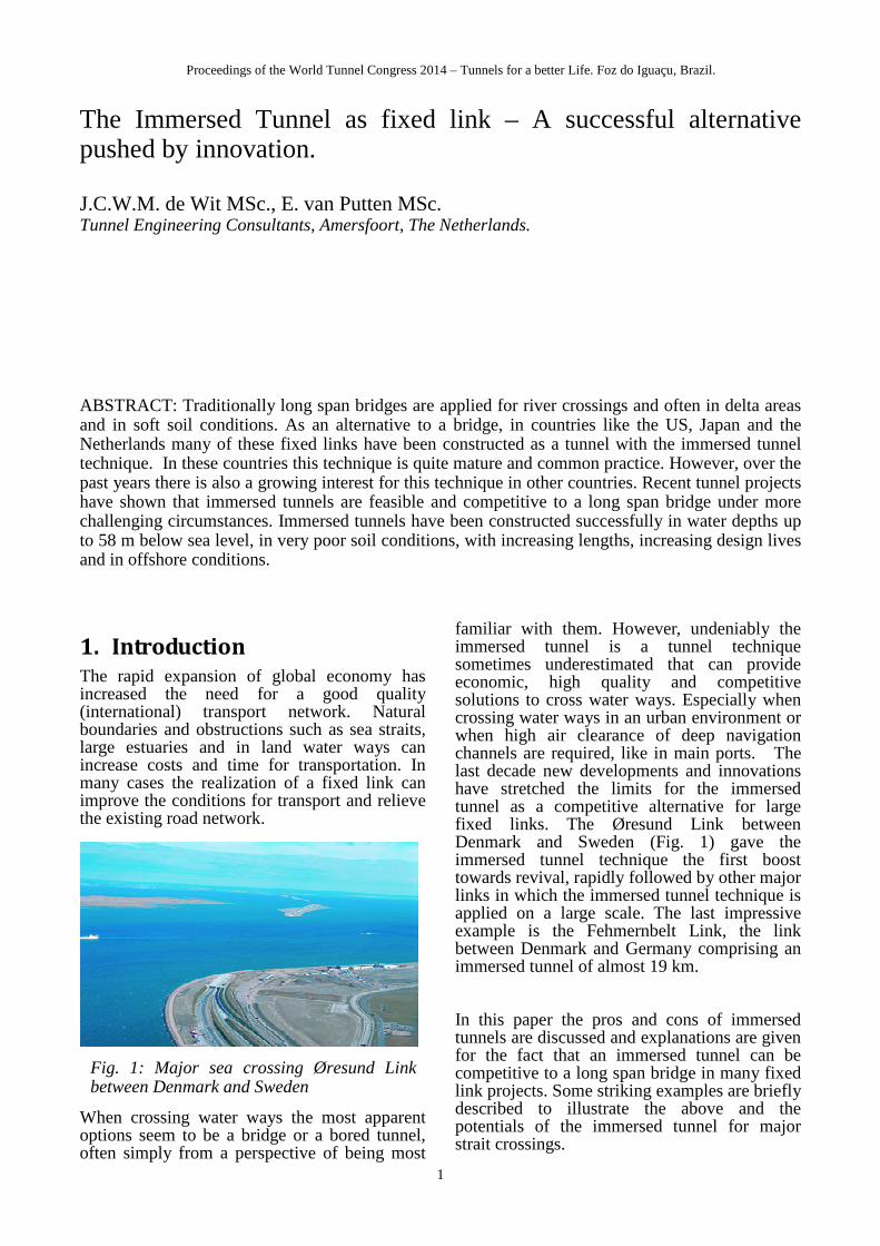
port, with a total length of approx. 1.500 m, accommodating 2x3 road lanes and a service / escape duct (Fig.12).
The tunnel comprises an immersed section of 700m. The tunnel was constructed to replace an existing bridge in the motorway A15 that contained a movable part that opened 8.000 times a year to allow the passage of the sea-vessels (Fig.13).
Fig.12: Typical cross section immersed tunnel

Proceedings of the World Tunnel Congress 2014 – Tunnels for a better Life. Foz do Iguaçu, Brazil.
6
Due to the fact that the water way was relatively narrow (around 250 m) and the required air clearance was at least 50 m a high level bridge was not considered to be a serious option, due to the fact that the long approaches would be very costly and a lot more difficult to integrate in the road network. However the bored tunnel was compared in more detail, but appeared to be not competitive either. Due to the fact that a significant ground cover is required on top of the bored tunnel and much less favourable circular cross section for a 3-lane bored tunnel, the total tunnel length increased with some 50%, which was expressed in the comparative cost estimates as well (Fig.14).
6.2 Øresund Link, Denmark
The Øresund Link, a 16.7 km long tunnel and bridge link, carrying road and rail traffic between Copenhagen in Denmark and Malmö in Sweden. The tunnel is located at the western side of the Link, with the tunnel entrance next to Copenhagen airport. The transition between the tunnel and the bridge is accommodated by means of a large artificial island approx. 4 km long and south of Saltholm. At the Denmark shore a significant land reclamation extending
430 m in the sea was established. The immersed part of the tunnel has a length of 3500 m and runs under the Drodgen Channel. The tunnel is divided into 20 elements, each 176m long; each element is made up of 8 segments of 22m each. The tunnel includes two railway tubes, two motorway tubes and an escape gallery. The outer dimensions of the cross section are 8.5m by 41.7 m.
Innovative concepts The size of the tunnel project, the tight construction schedule and the environmental conditions urged for new innovative concepts to be introduced: 1. A new factory production method for tunnel elements was developed using full section casting which resulted in high quality concrete works in a tight but feasible construction schedule.
A new construction method was developed, also referred to as the cast and launch method. It comprises a factory construction of all tunnel concrete without resorting to a large excavation,
Fig.14: Comparison immersed and bored tunnel in design and costs
Fig.13: floating tunnel element arriving at site and passing under existing movable bridge
Fig.15: Øresund Link (aerial view)
Fig.16: Cross section immersed tunnel
Proceedings of the World Tunnel Congress 2014 – Tunnels for a better Life. Foz do Iguaçu, Brazil.
7
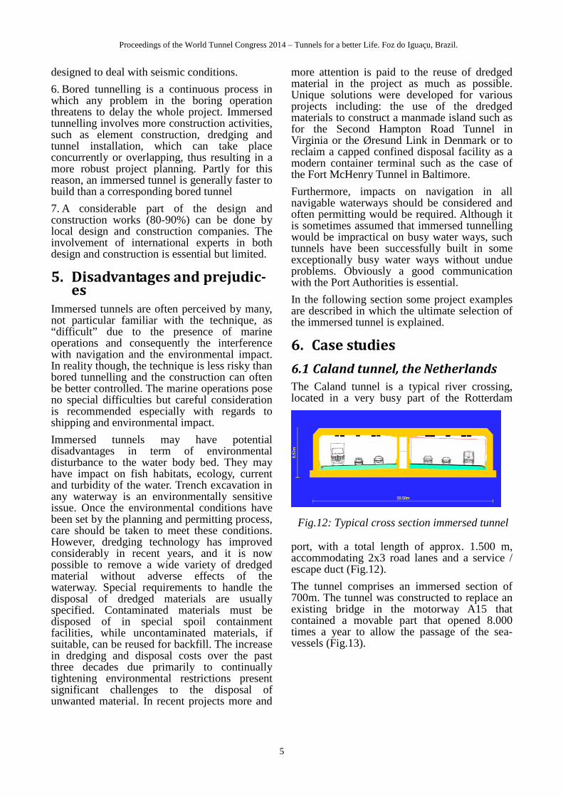
casting the tunnel elements in a single 30 hour concrete pour, full off line prefabrication of the reinforcement cages and transportation of completed tunnel elements some 300 m, sliding over skidding beams into the shallow basin. Then a sliding gate is closed between the factory and the element. Water is impounded within the dock to about 10m above sea level, allowing the tunnel element to float. It is then winched into deep water of the basin and lowered into the sea using the same principle as a ship lock. Whilst the completed element is being immersed in this way, the factory is able to continue with the construction of further tunnel elements.
In addition a full section casting was studied in order to limit early age stresses, particularly those associated with thermal effects. Traditional construction of tunnel elements, in which the tunnel cross section is cast in three stages involves this early age stress issue, since the first cast base slab constraints the later cast wall concrete, resulting in tension stresses in the walls that can cause through section cracking, resulting in leakage. These are normally mitigated by a waterproffing membrane or by cooling the concrete during the hardening process of the concrete using cats in water
pipes. The construction method chosen for the Øresund tunnel largely avoids this problem by casting each tunnel segment in a single pour (2600 m3 in about 30 hours) in which artificial cooling nor was a membrane not required. However, careful consideration was still needed for early age stress management. This included concrete mixture selection, pour sequence, ambient temperature control in the factory, selective insulation of the concrete and timing of all aspects of the production of a segment (pour, strip and jack sequence).
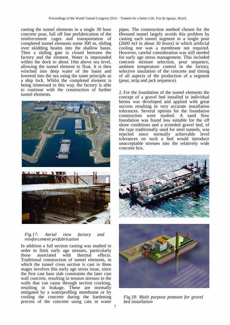
2. For the foundation of the tunnel elements the concept of a gravel bed installed in individual berms was developed and applied with great success resulting in very accurate installation tolerances. Several options for the foundation construction were studied. A sand flow foundation was found less suitable for the off shore conditions and a screeded gravel bed, of the type traditionally used for steel tunnels, was rejected since normally achievable level tolerances on such a bed would introduce unacceptable stresses into the relatively wide concrete box.
Fig.17: Aerial view factory and reinforcement prefabrication
Fig.18: Multi purpose pontoon for gravel bed installation
Proceedings of the World Tunnel Congress 2014 – Tunnels for a better Life. Foz do Iguaçu, Brazil.
8
Special equipment was developed to meet the design requirements for gravel bed installation. The basic principle for placing the bed is to feed the gravel down a pipe directly into position on the trench floor. The lower end of the pipe is equipped with a screeding plate, leaving the level the top of the gravel at the correct level as it is placed. The process is continuous and there is no secondary screeding operation. The feeder pipe is mounted on a multi purpose pontoon, fixed temporarily in position by spuds. The system appeared capable delivering an overall level accuracy of +25 mm from the design line throughout. This is achieved by a laser levelling system linked to hydraulic cylinders on the feeder pipe.
3. Environmental issues were considered to be of utmost importance. Special dredging methods were applied reducing the spillage of dredged material to a minimum. Continuous monitoring was carried out during the dredging operations to make sure the environment spillage requirements were met. At the same time dredged material was used to create the artificial islands.
6.3 Busan Geoje Crossing, South Ko-rea
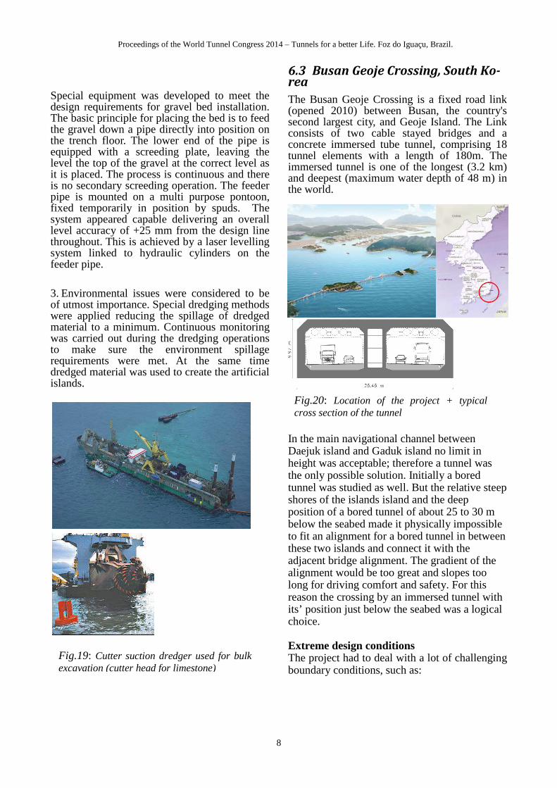
The Busan Geoje Crossing is a fixed road link (opened 2010) between Busan, the country's second largest city, and Geoje Island. The Link consists of two cable stayed bridges and a concrete immersed tube tunnel, comprising 18 tunnel elements with a length of 180m. The immersed tunnel is one of the longest (3.2 km) and deepest (maximum water depth of 48 m) in the world.
In the main navigational channel between Daejuk island and Gaduk island no limit in height was acceptable; therefore a tunnel was the only possible solution. Initially a bored tunnel was studied as well. But the relative steep shores of the islands island and the deep position of a bored tunnel of about 25 to 30 m below the seabed made it physically impossible to fit an alignment for a bored tunnel in between these two islands and connect it with the adjacent bridge alignment. The gradient of the alignment would be too great and slopes too long for driving comfort and safety. For this reason the crossing by an immersed tunnel with its’ position just below the seabed was a logical choice.
Extreme design conditions The project had to deal with a lot of challenging boundary conditions, such as:
Fig.19: Cutter suction dredger used for bulk excavation (cutter head for limestone)
Fig.20: Location of the project + typical cross section of the tunnel

Proceedings of the World Tunnel Congress 2014 – Tunnels for a better Life. Foz do Iguaçu, Brazil.
9
1. The geotechnical conditions at the project location are not very favorable. Marine clay forms the seabed along the tunnel alignment. The thickness of the marine clay exceeds 20m along most of the alignment and locally reaches a thickness of 30m, and this layer will form the foundation of the tunnel.
2. The site is exposed to the Pacific Ocean via the Korean Strait and the East China Sea at the south. This affects the marine conditions on site. The exposed location at the end of an estuary in a typhoon area results in significant wave heights up to 8m and currents up to 2 m/s. Offshore conditions involve current, wind waves and swell waves which make the transport and immersion of the tunnel element delicate stages.
Production of tunnel elements The construction of the tunnel elements is carried out in a temporary precast yard on the western side of the Jinhae Bay, about 40 km from the project location. The casting of the tunnel elements is carried out in two batches of four and two batches of five tunnel elements. The tunnel elements are 180 m long, 10 m high, 26 m wide and weigh about 48,000 tons. The tunnel elements are closed off with steel, reusable bulkhead panels on both ends.
After finishing each batch, the precast yard is flooded and the dock door is removed. The tunnel elements are floated up, flooded out of the casting basin and transported to a nearby mooring location. The tunnel elements are stored in floating conditions. Due to the sheltered area of the mooring location, the tunnel elements are not affected by swell waves and can be stored there throughout the year, even in the typhoon season. Offshore Transport and Immersion Offshore conditions involve current, wind waves and swell waves. Especially the swell waves are dominant in the design of the immersion system. Swell waves are long-crested, uniformly symmetrical waves that have travelled outside the area of their origin. Because swell waves have relative large wave length (>>50m) the long lined tunnel elements are more susceptible for these types of waves. The experience of performing the immersion operations under these offshore conditions is unique and a mayor challenge for the Busan Geoje Fixed Link project. It required newly designed innovative solutions which can deal with these conditions.
Fig.21: Indicative Geotechnical profile Fig.22: Temporary Mooring Location file
Fig.24: External Positioning System
Fig.23: Tunnel elements production
Proceedings of the World Tunnel Congress 2014 – Tunnels for a better Life. Foz do Iguaçu, Brazil.
10
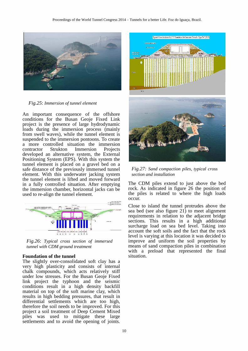
An important consequence of the offshore conditions for the Busan Geoje Fixed Link project is the presence of large hydrodynamic loads during the immersion process (mainly from swell waves), while the tunnel element is suspended to the immersion pontoons. To create a more controlled situation the immersion contractor Strukton Immersion Projects developed an alternative system, the External Positioning System (EPS). With this system the tunnel element is placed on a gravel bed on a safe distance of the previously immersed tunnel element. With this underwater jacking system the tunnel element is lifted and moved forward in a fully controlled situation. After emptying the immersion chamber, horizontal jacks can be used to re-align the tunnel element.
Foundation of the tunnel The slightly over-consolidated soft clay has a very high plasticity and consists of internal chalk compounds, which acts relatively stiff under low stresses. For the Busan Geoje Fixed link project the typhoon and the seismic conditions result in a high density backfill material on top of the soft marine clay, which results in high bedding pressures, that result in differential settlements which are too high, therefore the soil needs to be improved. For this project a soil treatment of Deep Cement Mixed piles was used to mitigate these large settlements and to avoid the opening of joints.
The CDM piles extend to just above the bed rock. As indicated in figure 26 the position of the piles is related to where the high loads occur.
Close to island the tunnel protrudes above the sea bed (see also figure 21) to meet alignment requirements in relation to the adjacent bridge sections. This results in a high additional surcharge load on sea bed level. Taking into account the soft soils and the fact that the rock level is varying at this location it was decided to improve and uniform the soil properties by means of sand compaction piles in combination with a preload that represented the final situation.
Fig.25: Immersion of tunnel element
Fig.26: Typical cross section of immersed tunnel with CDM ground treatment
Fig.27: Sand compaction piles, typical cross section and installation

Proceedings of the World Tunnel Congress 2014 – Tunnels for a better Life. Foz do Iguaçu, Brazil.
11
6.4 Hongkong Zhuhai Macao Link, China
Currently the Hong Kong Zhuhai Macao Bridge Link (HZMB) is under construction. The main project covers the offshore section of the HZMB Link of approx. 30km, crossing the Pearl River Estuary from the border with Hong Kong to Macao and Zhuhai (Mainland China). The Link comprises various bridges, artificial islands and tunnels.
The Link will accommodate a dual carriageway with 3 traffic lanes in each direction. To allow the passage of sea going vessels major cable stayed bridges will be included in the Design of the Link. The crossing of the main shipping channels at the eastern side of the Pearl River Estuary will be realised using a 6.75km long tunnel, of which approx. 6km will be immersed. The transition from the bridges to the tunnel will be realised with artificial islands with a length of 625m each.
The selection of the preferred option The selection of the immersed tunnel was made after a careful consideration of both the bridge and bored tunnel option. For the bridge option crossing of the main navigation channels with the required air clearance of over 60 m resulted in a major suspension bridge spanning both channels and with towers of over 100m in height. Since this bridge would interfere with the aviation requirements for the approach of Hong Kong International Airport the bridge option had to be rejected.
The bored tunnel option was studied in detail during the conceptual design stage and compared to the immersed tunnel option. The design consisted of two bored tunnels with an outer diameter of 16.9 m in order to accommodate 2 x 3 road lanes. On regular distances cross passages were included to meet
safety requirements. The vertical alignment dropped from -40m for the immersed tunnel to -54m for the bored tunnel. The tunnel length increased from 6.6km for the immersed tunnel to 7.2km for the bored tunnel. The length of the artificial island increased with some 250m per island.
The main reasons to select the immersed tunnel as preferred option were costs, risks and schedule:
1. Cost estimates indicated that the bored tunnel was approx. 10-15% more expensive than the immersed tunnel. This included the additional costs for the artificial islands and maintenance and operation of the tunnel.
2. From a risk point of view the immersed tunnel performed better than the bored tunnel. Especially the geotechnical risks associated with variable ground conditions were supposed to be better manageable with the immersed tunnel. The very large 16.9m diameter in combination with the wide variety of soils that would be encountered (weak soils � hard rock) would be a major challenge for the Tunnel Boring Machines.
3. The construction time for the bored tunnel was estimated to take 10 months longer than for the bored tunnel. In addition the planning risks were considered larger for the bored tunnel.
Tunnel Design The tunnel structure design was faced with a set of challenging design requirements and boundary conditions:
- The three lane road design requires large spans for the traffic tubes of 14.55m.
- The tunnel is placed at a deep level of 29 m below the lowest design sea level, to allow the future passage of 300.000 tons oil tankers in two navigation channels with a total width of 2.810m. Since the navigation channels will only be dredged in the future the immersion trench is allowed to fill with sedimentation up to the existing sea bed level, which means a ground cover that can exceed 20 m.
- The geotechnical conditions are relatively poor and variable. The seabed level in this area varies between -8m and -15m. Holocene soft deposits
Fig.28: Project Location
Fig.29: Indicative geotechnical profile

Proceedings of the World Tunnel Congress 2014 – Tunnels for a better Life. Foz do Iguaçu, Brazil.
12
of a thickness from 10-25 m are found below the seabed and overlying Late Pleistocene (over consolidated clays, sands and gravel) with a thickness that varies between 37m and 102m (locally). Underneath the Pleistocene deposits rock / granite is encountered.
Indicative analyses which included soil structure interaction had shown that direct foundation of the tunnel element in the soft layers was only possible when ground treatment was introduced. In this way the settlements and differential settlements can be limited and therefore the internal design forces in the tunnel. In addition ground treatment is applied to promote smooth transition from one tunnel part (e.g. piled cut and cover tunnel at the islands) to the other (e.g. immersed tunnel). Replacement of soft layers by gravel is applied where the soft layers are thin. On other locations where the thickness of the soft layer is large, sand compaction piles are applied. In the more sensitive areas this was done in combination with pre-loading. The replacement ratio varies from 70% to 40%.
The fact that the tunnel element must be able to float during transport and immersion stages implies that there are limitations to the structural dimensions as they determine most of the weight of the (floating) tunnel. For the cross section design the conventional reinforced concrete option was compared with an option with post tensioning in transverse direction (in roof and base slab). Finally it was concluded that the conventional reinforced option was still preferred when considering costs, risks and the execution of the works.
Island Design In the HZMB Link the transition between the bridges and the immersed tunnel will be realized by means of artificial islands. The islands are approximately 625 m long and 160 m wide. At the islands also the technical service buildings for the tunnel are located. In figure 32 the general lay out of the islands is presented.
As for the tunnel the geotechnical conditions for the construction of the artificial islands are not very favourable. Since large land reclamations and extensive back fill operations are involved the geotechnical design is quite delicate in order to meet the settlement requirements that were defined. The design of the islands includes: - Excavate soft top layers of mud - Sand compaction piles to improve underly-
ing cohesive layers - Installation of circular steel cylinders as re-
taining structures - Construct cut and cover tunnel founded on
bored piles Formation of the sea defence walls consisting of rock layers and revetments of doloses
Fig.30: Indicative lay out sand compaction piles
Fig 31: Typical Cross Section Immersed Tunnel (outer dimensions approx. 11.5m * 38 m)
Fig.32: Illustrations artificial islands and tunnel entrance (on island)

Proceedings of the World Tunnel Congress 2014 – Tunnels for a better Life. Foz do Iguaçu, Brazil.
13
Ventilation concept
The length of the sub-sea tunnel, which stands at +6km, poses specific challenges while considering tunnel safety. Tunnel ventilation is an essential item of the tunnel safety concept when it comes to the operational phase and regarding incident control.
A ventilation concept has been selected with longitudinal ventilation in the operational phase (jet fans supported by natural ventilation induced by the piston effect and enhanced by the traffic). In case of a fire a parallel smoke extraction system will be activated using a point extraction ventilation system including a separate smoke extraction cell (located above the escape cell) combined with an additional system like foam mist fire extinguishing system or a sprinkler system.
Finally
Currently the immersion process is ongoing. At the beginning of 2014 some 10 elements out of the 33 elements are being immersed. For the construction of the tunnel elements the cast and launch method in a factory (like the Øresund tunnel) is being used.
Fig.33: Construction of artificial island steel cylinders and preparation cut & cover tunnel
Fig.34: Ventilation principle in operation phase and during a fire
Fig.35: Construction stages in tunnel element factory

Proceedings of the World Tunnel Congress 2014 – Tunnels for a better Life. Foz do Iguaçu, Brazil.
14
6.5 Fehmarnbelt Fixed Link, Den-mark and Germany
The Fehmarnbelt Fixed Link will connect Scandinavia and continental Europe with a combined rail and road connection between Denmark and Germany. It is planned to cross the Fehmarnbelt between Rødbyhavn on the island of Lolland in Denmark, and Puttgarden located on the island of Fehmarn on the north coast of Germany. This immersed tunnel project will have a world-breaking distance of about 17.6 km, almost 5 times longer than the current record-holder. Other challenges are a water depth of 30 m, crossing of a busy navigational channel and strict environmental requirements.
The selection of the preferred option
In the late nineties a feasibility study was carried out for this fixed link and the Danish and German government labelled the cable stayed bridge as the preferred solution and the immersed tunnel as the best alternative. In 2009 two consultants were selected by the Client organization Fehmern A/S for a more detailed study of both solutions in an internal competitive process (Fig.37).
After a comprehensive comparison between a bridge and an immersed tunnel solution, in February 2011 the Danish government concluded that the immersed tunnel became the preferred solution.
The main raisons for the selection of the immersed tunnel were: - slightly lower in price - performing better in terms of availability due to the sheltered conditions from adverse weather and an state of the art maintenance concept - hydraulic impact is much less considering the many piers that are involved in the bridge option - less visual and environmental impact which was considered very important to satisfy the various stakeholders - the possibilities for local contractors and suppliers to get involved in the project were considered much higher
Immersed tunnel solution
The tunnel elements consist of a combined road and rail cross-section all at one level, contained within a concrete structure. There are two types of tunnel elements: - Standard elements, which represents the main part (>95%) of the immersed tunnel section. Each standard element has a maximum length of approximately 217 m. They have the same geometric layout and are, to a high degree, interchangeable. A high degree of standardization will allow an industrialized construction method such as developed for the Øresund project. - Special elements, about one every 1.8 km along the length of the immersed tunnel that provide space within the tunnel dedicated for mechanical and electrical equipment. The concentration of the tunnel installations and access facilities for maintenance staff in these special elements resulted in a further optimization of the standard elements. Underneath the road and rail tubes there will be access to all areas of the tunnel in order to reduce the disruption of the traffic to a minimum.
Fig.36: Project location and Elevation
Fig.37: Tunnel and Bridge option in competitive process

Proceedings of the World Tunnel Congress 2014 – Tunnels for a better Life. Foz do Iguaçu, Brazil.
15
Dredging and land reclamation
The tunnel elements are placed in a trench dredged into the seabed. Next to stringent requirements for the dredging works, an important strategy for this project has therefore been to re-use as much as possible of the dredged materials as resource for reclaiming new land in front of the shorelines of Lolland and Fehmern, respectively. Besides adding value to the environment the environmental impact is minimized by setting stringent requirements during both construction as well as the operational phase. These areas will be landscaped into green areas. By using the dredged materials beneficially to create natural landscapes and create added environmental, natural and recreational value to the project. This is obtained with the landscape elements such as beaches, dunes, armored dikes, wetland areas and a natural cliff, which is allowed to controllably erode and thereby supply the downstream coastline with sediments.
The size of the reclamation area on the German coastline is relative small. Two larger reclamations are planned on the Danish coastline on both sides of the existing harbour which will absorb the majority of the dredged material from the trench excavation.
Safety Concept / Tunnel Safety
Safety and self rescue are more prominent when tunnel length increases. The safety level is higher compared to when travelling on a motorway or railway due to the absence of adverse weather conditions, turn outs, crossings and the constant light level in the tunnel. However, the consequences of an accident in the tunnel may be higher, especially when fire is involved. Therefore, a great number of provisions are implemented to manage incidents in a manner that provides adequate safety. The safety strategy has been based on three levels and three key objectives: 1. Prevention of accidents and fires through design and operation,
2. Control of incidents and self rescue of users in case of an incident. This is important because due to the length of the tunnel the response of emergency services inevitably takes time
3. Emergency response and rescue.
The primary safety objective for safety level 1 is to provide a tunnel solution that will prevent accidents and other emergency situations occurring. It has been achieved through both design and operational considerations. Special attention was paid to highly reliable traffic information and management systems and safe driving conditions that significantly tribute to the prevention of accidents.
Fig.38: Cross section Standard and Special Element
Fig.39: Lay out of land reclamation on Danish Side with in dotted red the existing shore line
Fig.40: Traffic information and drivers’ awareness lighting
HIGH INFORMATION LEVEL –
VARIABLE MESSAGE SIGNS
Proceedings of the World Tunnel Congress 2014 – Tunnels for a better Life. Foz do Iguaçu, Brazil.
16
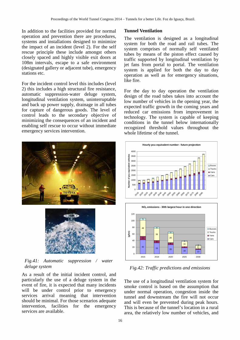
In addition to the facilities provided for normal operation and prevention there are procedures, systems and installations designed to minimize the impact of an incident (level 2). For the self rescue principle these include amongst others closely spaced and highly visible exit doors at 108m intervals, escape to a safe environment (designated gallery or adjacent tube), emergency stations etc. For the incident control level this includes (level 2) this includes a high structural fire resistance, automatic suppression-water deluge system, longitudinal ventilation system, uninterruptable and back up power supply, drainage in all tubes for capture of dangerous goods. The level of control leads to the secondary objective of minimizing the consequences of an incident and enabling self rescue to occur without immediate emergency services intervention.
As a result of the initial incident control, and particularly the use of a deluge system in the event of fire, it is expected that many incidents will be under control prior to emergency services arrival meaning that intervention should be minimal. For those scenarios adequate intervention, facilities for the emergency services are available.
Tunnel Ventilation
The ventilation is designed as a longitudinal system for both the road and rail tubes. The system comprises of normally self ventilated tubes by means of the piston effect caused by traffic supported by longitudinal ventilation by jet fans from portal to portal. The ventilation system is applied for both the day to day operation as well as for emergency situations, like fire.
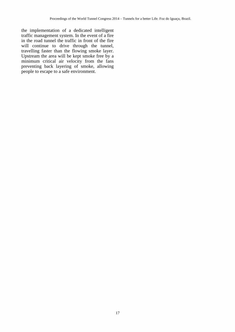
For the day to day operation the ventilation design of the road tubes takes into account the low number of vehicles in the opening year, the expected traffic growth in the coming years and reduced car emissions from improvement in technology. The system is capable of keeping conditions in the tunnel below internationally recognized threshold values throughout the whole lifetime of the tunnel.
The use of a longitudinal ventilation system for smoke control is based on the assumption that under normal operation, congestion inside the tunnel and downstream the fire will not occur and will even be prevented during peak hours. This is because of the tunnel’s location in a rural area, the relatively low number of vehicles, and
Fig.41: Automatic suppression / water deluge system
Hourly pcu equivalent number - future projection
0
500
1000
1500
2000
2500
3000
3500
4000
2018
2020
2025
2030
2035
2040
2045
2050
2055
2060
2065
2070
2075
2080
2085
Nu
mb
er o
f p
cu e
qu
ival
ent
veh
icle
s
Buses
Trucks
Vans
Cars
NO2 emissions - 30th largest hour in one direction
4233 28
18 13
11
86
32
49
36
28
16
11
5
4
3
1
1
0
20
40
60
80
100
120
2015 2018 2020 2025 2030
(g/k
m)
Busses
Trucks
Vans
Cars
Fig.42: Traffic predictions and emissions
Proceedings of the World Tunnel Congress 2014 – Tunnels for a better Life. Foz do Iguaçu, Brazil.
17
the implementation of a dedicated intelligent traffic management system. In the event of a fire in the road tunnel the traffic in front of the fire will continue to drive through the tunnel, travelling faster than the flowing smoke layer. Upstream the area will be kept smoke free by a minimum critical air velocity from the fans preventing back layering of smoke, allowing people to escape to a safe environment.