Paper 15-Eyes Based Eletric Wheel Chair Control System
8
(IJACSA) International Journal of Advanced Computer Science and Applications, Vol. 2, No. 12, 2011 98 | Page www.ijacsa.thesai.org Eyes Based Eletric Wheel Chair Control System - I (eye) can control Electric Wheel Chair - Kohei Arai Department of Information Science Saga University Saga City, Japan Ronny Mardiyanto Graduate School of Science and Engineering Saga University Saga City, Japan Abstract — Eyes base Electric Wheel Chair Control: EBEWC is proposed. The proposed EBEWC is controlled by human eyes only. Therefore disabled person can control the EBEWC by themselves. Most of the computer input system with human eyes only consider in specific condition and does not work in a real time basis. Moreover, it is not robust against various user races, illumination conditions, EWC vibration, and user's movement. Though experiments, it is found that the proposed EBEWC is robust against the aforementioned influencing factors. Moreover, it is confirmed that the proposed EBEWC can be controlled by human eyes only accurately and safely. Keywords-computer input by human eyes only; gaze estimation; electric wheelchair control. I. I NTRODUCTION The existing computer input devices such as keyboard, mouse, and the other input devices have been used to interact with digital instruments. These computer input devices cannot be operated by handicap persons. In this paper, a computer input device by human eyes only is proposed for handicap person and also for wearable computing. The existing computer input devices without finger, voice, and gesture can be divided into five categories; (1) Bio-potential based method which utilizes potential from user's body actions acquired by using special instrument. Instrument such as Electrooculograph (EOG), Electromyograph (EMG) [1], and Electroencephalograph (EEG) [2], Search coil can be used for measuring bio-potential. The search coil output can be used as sources of computer input for handicap person. EOG method [7], [16] uses voltage differences between fore and aft surface of eyes. (2) Voice Based method [3], which use user's voice as source input. Voice analysis is used to analyze user's voice and convert into digital data. The weakness of this system is vulnerable against noise. Other voices which come from surrounding user may affect the system. (3) Motion based method [4], utilizes other normal movement organs to operate computer input. Head, foot, and etc can be used to control computer input. (4) Image Analysis method [10]-[15], utilizes camera to analyze user's desire and convert into digital data. Several image processing methods are used to analyze user's desire. The user's desire itself can be done by Gaze based [5], [6], [9], analyze user's desire from users gaze, Face based analyze user's desire from face expression, and the others. (5) Search coil method [8] uses induced voltage with coil including in contact lenses attached to user’s eyes. Methods (1) and (5) insists psychological and physical burden to users because these methods require direct sensors which are attached to user’s face. Also these methods are relatively costly. On the other hand, the image analysis method does not insist any load to users and is realized with comparatively cheap cost. For the aforementioned reason, we propose an image analysis based method. Electric Wheel Chair: EWC for assisted mobility is presented [16]-[20]. There is the proposed system for assisted mobility using eye movements based on Electrooculography. EWC is controlled by eye movement which is acquired using Electrooculograph [16]. Also there is the proposed integrated solution to motion planning and control with input from three sources [17]. At the highest level, the human operator can specify goal destination using visual interface by pointing to location or features on display. This input lets the chair automatically generate a deliberative plan incorporating prior knowledge. At the intermediate level, the human operator must use reactive controller to avoid obstacle and features that the sensor detect. At the lowest level, the human operator can directly provide velocity command using joystick. There is the proposed vision-based navigation for an electric wheelchair using ceiling light landmark [18]. The wheelchair is equipped with two cameras those are used for self-location and obstacle avoidance. The fluorescent ceiling lights are chosen as landmarks since they can be easily detected and do not require an additional installation. Also there is the proposed head gesture based control of an intelligent wheelchair [19]. This system used Adaboost face detection. By detecting frontal face and nose position, head gesture is estimated and used to control the wheelchair. There is the proposed EWC control with gaze direction and eye blinking [20]. The gaze direction is expressed by horizontal angle of gaze, and it is derived from the triangle form formed by the center position of eyes and nose. The gaze direction and eye blinking are used to provide the direction and timing
-
Upload
editor-ijacsa -
Category
Documents
-
view
219 -
download
0
Transcript of Paper 15-Eyes Based Eletric Wheel Chair Control System
8/3/2019 Paper 15-Eyes Based Eletric Wheel Chair Control System
http://slidepdf.com/reader/full/paper-15-eyes-based-eletric-wheel-chair-control-system 1/8
(IJACSA) International Journal of Advanced Computer Science and Applications,Vol. 2, No. 12, 2011
98 | P a g e
www.ijacsa.thesai.org
Eyes Based Eletric Wheel Chair Control System- I (eye) can control Electric Wheel Chair -
Kohei Arai
Department of Information ScienceSaga University
Saga City, Japan
Ronny Mardiyanto
Graduate School of Science and EngineeringSaga University
Saga City, Japan
Abstract — Eyes base Electric Wheel Chair Control: EBEWC isproposed. The proposed EBEWC is controlled by human eyes
only. Therefore disabled person can control the EBEWC bythemselves. Most of the computer input system with human eyesonly consider in specific condition and does not work in a realtime basis. Moreover, it is not robust against various user races,
illumination conditions, EWC vibration, and user's movement.Though experiments, it is found that the proposed EBEWC isrobust against the aforementioned influencing factors. Moreover,
it is confirmed that the proposed EBEWC can be controlled byhuman eyes only accurately and safely.
Keywords-computer input by human eyes only; gaze estimation;electric wheelchair control.
I. I NTRODUCTION
The existing computer input devices such as keyboard,mouse, and the other input devices have been used to interactwith digital instruments. These computer input devices cannot
be operated by handicap persons. In this paper, a computer input device by human eyes only is proposed for handicap
person and also for wearable computing.
The existing computer input devices without finger, voice,and gesture can be divided into five categories;
(1) Bio-potential based method which utilizes potentialfrom user's body actions acquired by using specialinstrument. Instrument such as Electrooculograph(EOG), Electromyograph (EMG) [1], andElectroencephalograph (EEG) [2], Search coil can
be used for measuring bio-potential. The search coiloutput can be used as sources of computer input for handicap person. EOG method [7], [16] uses voltagedifferences between fore and aft surface of eyes.
(2) Voice Based method [3], which use user's voice assource input. Voice analysis is used to analyze user'svoice and convert into digital data. The weakness of this system is vulnerable against noise. Other voiceswhich come from surrounding user may affect thesystem.
(3) Motion based method [4], utilizes other normalmovement organs to operate computer input. Head,foot, and etc can be used to control computer input.
(4) Image Analysis method [10]-[15], utilizes camera toanalyze user's desire and convert into digital data.
Several image processing methods are used toanalyze user's desire. The user's desire itself can bedone by Gaze based [5], [6], [9], analyze user'sdesire from users gaze, Face based analyze user'sdesire from face expression, and the others.
(5) Search coil method [8] uses induced voltage withcoil including in contact lenses attached to user’seyes.
Methods (1) and (5) insists psychological and physical burden to users because these methods require direct sensorswhich are attached to user’s face. Also these methods arerelatively costly. On the other hand, the image analysis methoddoes not insist any load to users and is realized withcomparatively cheap cost. For the aforementioned reason, we
propose an image analysis based method.
Electric Wheel Chair: EWC for assisted mobility is presented [16]-[20]. There is the proposed system for assistedmobility using eye movements based on Electrooculography.EWC is controlled by eye movement which is acquired usingElectrooculograph [16]. Also there is the proposed integratedsolution to motion planning and control with input from three
sources [17]. At the highest level, the human operator canspecify goal destination using visual interface by pointing tolocation or features on display. This input lets the chair automatically generate a deliberative plan incorporating prior knowledge. At the intermediate level, the human operator mustuse reactive controller to avoid obstacle and features that thesensor detect. At the lowest level, the human operator candirectly provide velocity command using joystick. There is the
proposed vision-based navigation for an electric wheelchair using ceiling light landmark [18]. The wheelchair is equippedwith two cameras those are used for self-location and obstacleavoidance. The fluorescent ceiling lights are chosen aslandmarks since they can be easily detected and do not requirean additional installation. Also there is the proposed head
gesture based control of an intelligent wheelchair [19]. Thissystem used Adaboost face detection. By detecting frontal faceand nose position, head gesture is estimated and used to controlthe wheelchair.
There is the proposed EWC control with gaze direction andeye blinking [20]. The gaze direction is expressed by horizontalangle of gaze, and it is derived from the triangle form formed
by the center position of eyes and nose. The gaze direction andeye blinking are used to provide the direction and timing
8/3/2019 Paper 15-Eyes Based Eletric Wheel Chair Control System
http://slidepdf.com/reader/full/paper-15-eyes-based-eletric-wheel-chair-control-system 2/8
(IJACSA) International Journal of Advanced Computer Science and Applications,Vol. 2, No. 12, 2011
99 | P a g e
www.ijacsa.thesai.org
command. The direction command related to the movementdirection of EWC and the timing command related to the timecondition when the EWC should move.
In this paper, we propose computer input system withhuman eye-only and used for controlling EWC. It is called EyeBased EWC: EBEWC hereafter. EBEWC works based on eyegaze. When user looks at appropriate angle/key, then computer input system will send command to EWC. EBEWC is
controlled by three keys: left (Turn left), right (Turn right), anddown (Move forward) in order to give command to electricwheelchair: turn left, turn right, and go forward. This threecombination keys are more safely than others combinationkeys. The stop key is not required because EWC willautomatically stop when user change the gaze. Gaze estimationsystem still faced with problem such as robustness against avariety of user types, accuracy, illumination changes, vibration,and calibration.
In order to estimate gaze based on image analysis, it iscommon that gaze location is estimated with pupil location.The previously published pupil detection methods can bedivided into two categories: the active Infrared: IR-based
approaches [22], [23], [31] and the traditional image-based passive approaches [24]-[30]. Eye detection based on Houghtransform is proposed [24]-[26]. Hough transform is used for finding the pupil. Eye detection based on motion analysis is
proposed [21], [22]. Infrared lighting is used to capture the physiological properties of eyes (physical properties of pupilsalong with their dynamics and appearance to extract regionswith eyes). Motion analysis such as Kalman filter and meanshift which are combined with Support Vector Machine: SVMused to estimate pupil location. Eye detection using adaptivethreshold and morphologic filter is proposed [27]. Morphologicfilter is used to eliminate undesired candidates for an eye.Hybrid eye detection using combination between color, edgeand illumination is proposed [30].
In order to estimate the gaze, we use pupil knowledge for improvement on robustness against different users. In gazeestimation based on image analysis, almost all utilize pupillocation as reference. In this stage, pupil detection accuracy isvery important because all the gaze calculations are made
based on the detected pupil location. Many researches did notgive much attention on this part because most of them use idealimages as the source in order to find pupil location. When user looks at forward, pupil can be detected clearly. Meanwhile, it isusually not so easy to detect pupil location when user looks theother directions. A variety of skin colors, races, interferencewith eye lids, disappearances, and changes of eye shape (wheneye move) make the pupil detection very difficult. Pupilknowledge such as shape, size, location, and motion are used in
the proposed method. This knowledge works based on theknowledge priority.
Pupil appearance such as size, color, and shape are used asfirst priority. When this step fails, then pupil is estimated basedon its location as second priority. When all steps fails, pupil isestimated based on its motion as last priority. Last, we use eyemodel in order to convert pupil location into gaze direction.This gaze direction will be used to control EWC. In order to
improve the robustness against user's movement, illuminationchanging, and vibration, IR camera mounted glass is used.
The proposed system is tested by several users withdifferent race and nationality. The experimental results with the
proposed eye gaze estimation method are compared to well-known adaptive threshold method and template matchingmethod. Also robustness against illumination changing, noiseinfluence, vibration, and accuracy has been confirmed. In the
section 2, the proposed EBEWC system is described followed by some experimental results. Then section 4 describes somediscussions followed by conclusion.
II. PROPOSED METHOD
The problem of the utmost importance of a proposedEBEWC system is the robustness against different user types,illumination changes, user's movement, vibration, andaccuracy. In order to consider these as vehicle system, if theuser changes, the system should be works without any input
parameter changes. In accordance with EWC movement,illumination condition may change. Also, disturbances due toEWC vibration is potentially problem.
In the conventional EWC control system with human eyesonly, camera is mounted on EWC. This may cause a vulnerablewhen EWC is vibrated. Also, when user moves their head, gazeestimation is difficult. Furthermore, illumination condition maychange during EWC movement. The proposed EBEWC systemutilizes IR camera which mounted on user's glass. This waywill eliminate problems of illumination changes, user'smovement, and EWC vibration. Furthermore, the pupildetection based on pupil knowledge will improve therobustness against different users.
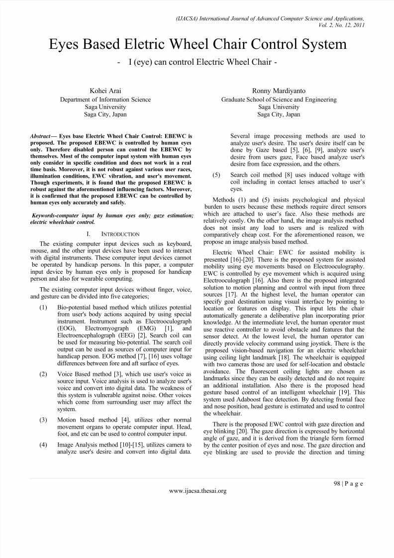
A. Hardware Configuration
Hardware configuration of the proposed EBEWC is shownin Fig.1.
Figure 1. Hardware Configuration
Netbook of Asus EeePC with 1.6 GHz Intel Atom processor, 1GB of RAM, 160GB hard drive, and run Windows
WheelchairController
Microcontroller
Netbook PC
Camera
8/3/2019 Paper 15-Eyes Based Eletric Wheel Chair Control System
http://slidepdf.com/reader/full/paper-15-eyes-based-eletric-wheel-chair-control-system 3/8
(IJACSA) International Journal of Advanced Computer Science and Applications,Vol. 2, No. 12, 2011
100 | P a g e
www.ijacsa.thesai.org
XP Home edition is used. We develop our software under C++Visual Studio 2005 and Intel provided OpenCv image
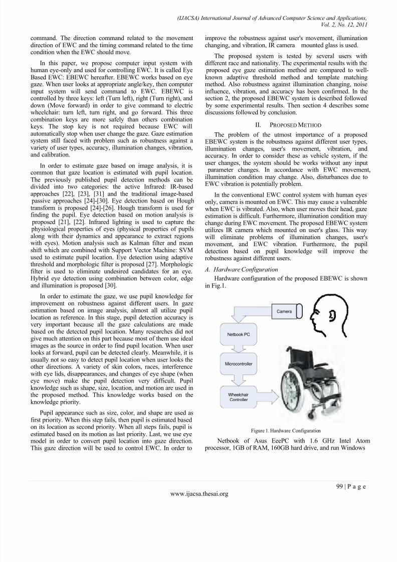
processing library [21]. The proposed EBEWC system utilizesinfrared web camera, NetCowBoy DC-NCR 131 as face imageacquisition in a real time basis. This camera has IR LightEmission Diode: LED. Therefore it is robust againstillumination changes. In order to allow user movement andEWC vibration, IR Camera mounted glass is used. The distance
between camera and eye is set at 15.5 cm as shown in Fig.2.The EBEWC uses Yamaha JWX-1 type of EWC which iscontrolled by human eyes only through microcontroller of AT89S51. This microcontroller can convert serial output from
Netbook to digital output for control.
Figure 2. Electric Wheelchair Hardware
In order to control EWC using Netbook PC, custom microcontroller circuit is used to modify standard control of YamahaEWC. Default control of the EWC is made by joystick. Microcontroller is replaced to the joystick. Command is delivered by
Netbook PC, and then micro controller works to move EWC.USB interface on Netbook PC is used to connect with the other
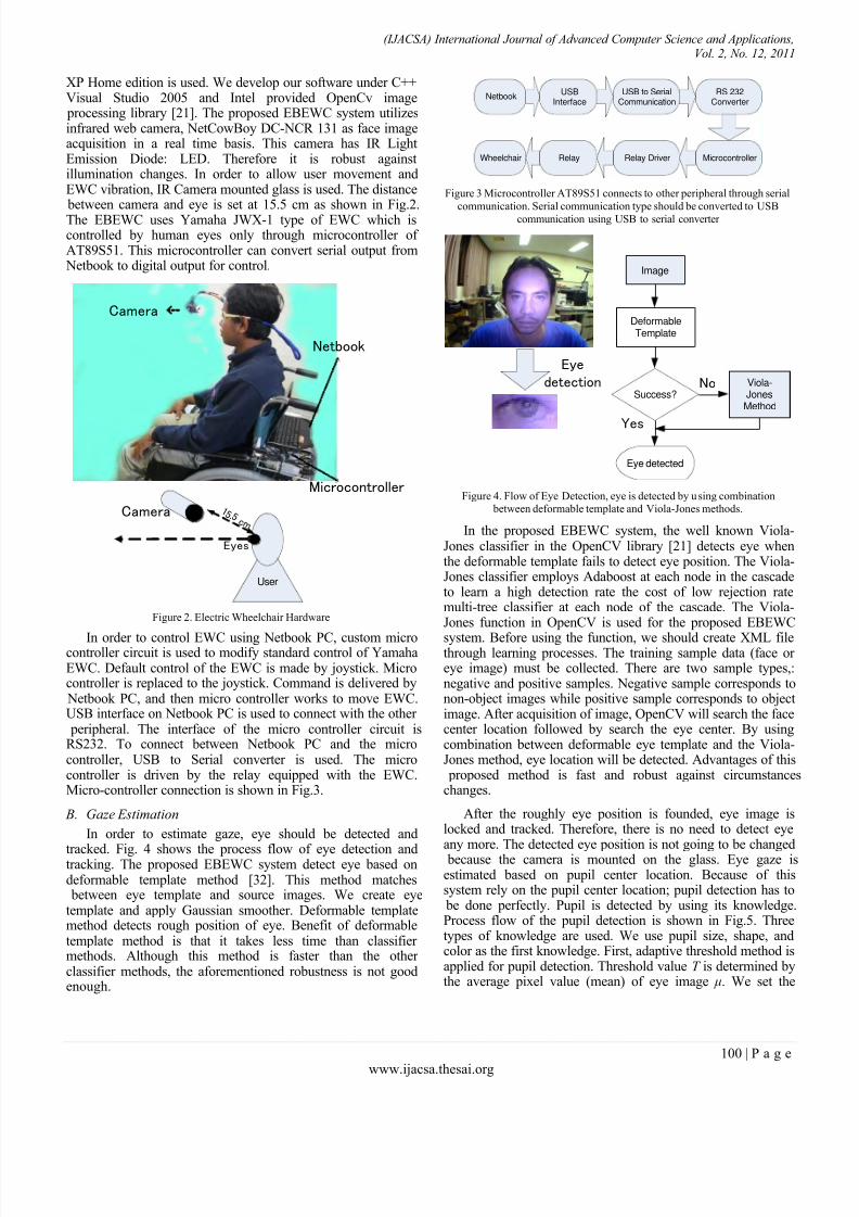
peripheral. The interface of the micro controller circuit isRS232. To connect between Netbook PC and the microcontroller, USB to Serial converter is used. The microcontroller is driven by the relay equipped with the EWC.Micro-controller connection is shown in Fig.3.
B. Gaze Estimation
In order to estimate gaze, eye should be detected and
tracked. Fig. 4 shows the process flow of eye detection andtracking. The proposed EBEWC system detect eye based ondeformable template method [32]. This method matches
between eye template and source images. We create eyetemplate and apply Gaussian smoother. Deformable templatemethod detects rough position of eye. Benefit of deformabletemplate method is that it takes less time than classifier methods. Although this method is faster than the other classifier methods, the aforementioned robustness is not goodenough.
Figure 3 Microcontroller AT89S51 connects to other peripheral through serial
communication. Serial communication type should be converted to USB
communication using USB to serial converter
Figure 4. Flow of Eye Detection, eye is detected by u sing combination between deformable template and Viola-Jones methods.
In the proposed EBEWC system, the well known Viola-Jones classifier in the OpenCV library [21] detects eye whenthe deformable template fails to detect eye position. The Viola-Jones classifier employs Adaboost at each node in the cascadeto learn a high detection rate the cost of low rejection ratemulti-tree classifier at each node of the cascade. The Viola-Jones function in OpenCV is used for the proposed EBEWC
system. Before using the function, we should create XML filethrough learning processes. The training sample data (face or eye image) must be collected. There are two sample types,:negative and positive samples. Negative sample corresponds tonon-object images while positive sample corresponds to objectimage. After acquisition of image, OpenCV will search the facecenter location followed by search the eye center. By usingcombination between deformable eye template and the Viola-Jones method, eye location will be detected. Advantages of this
proposed method is fast and robust against circumstanceschanges.
After the roughly eye position is founded, eye image islocked and tracked. Therefore, there is no need to detect eyeany more. The detected eye position is not going to be changed
because the camera is mounted on the glass. Eye gaze isestimated based on pupil center location. Because of thissystem rely on the pupil center location; pupil detection has to
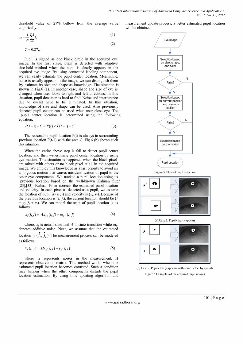
be done perfectly. Pupil is detected by using its knowledge.Process flow of the pupil detection is shown in Fig.5. Threetypes of knowledge are used. We use pupil size, shape, andcolor as the first knowledge. First, adaptive threshold method isapplied for pupil detection. Threshold value T is determined bythe average pixel value (mean) of eye image μ. We set the
Camera
Netbook
Microcontroller
User
Camera
Eyes
1 5 ,5 c m
Netbook
USBInterface
USB to SerialCommunication
RS 232Converter
MicrocontrollerRelay DriverRelayWheelchair
Eye
detection
Image
Viola-JonesMethod
Success?
Eye detected
DeformableTemplate
Yes
No
8/3/2019 Paper 15-Eyes Based Eletric Wheel Chair Control System
http://slidepdf.com/reader/full/paper-15-eyes-based-eletric-wheel-chair-control-system 4/8
(IJACSA) International Journal of Advanced Computer Science and Applications,Vol. 2, No. 12, 2011
101 | P a g e
www.ijacsa.thesai.org
threshold value of 27% bellow from the average valueempirically.
1
0
1 N
i
i I N
27.0T
(1)
(2)
Pupil is signed as one black circle in the acquired eyeimage. In the first stage, pupil is detected with adaptivethreshold method when the pupil is clearly appears in theacquired eye image. By using connected labeling component,we can easily estimate the pupil center location. Meanwhile,noise is usually appears in the image, we can distinguish them
by estimate its size and shape as knowledge. The situation isshown in Fig.6 (a). In another case, shape and size of eye ischanged when user looks to right and left directions. In thissituation, pupil detection is hard to find. Noise and interferencedue to eyelid have to be eliminated. In this situation,knowledge of size and shape can be used. Also previouslydetected pupil center can be used when user close eye. The
pupil center location is determined using the following
equation,C t P t P C t P )1()()1( (3)
The reasonable pupil location P(t) is always in surrounding previous location P(t-1) with the area C. Fig.6 (b) shows suchthis situation.
When the entire above step is fail to detect pupil center location, and then we estimate pupil center location by usingeye motion. This situation is happened when the black pixelsare mixed with others or no black pixel at all in the acquiredimage. We employ this knowledge as a last priority to avoid anambiguous motion that causes misidentification of pupil to theother eye components. We tracked a pupil location using its
previous location based on the well-known Kalman filter [23],[33]. Kalman Filter corrects the estimated pupil locationand velocity. In each pixel as detected as a pupil, we assumethe location of pupil is (it , jt ) and velocity is (ut , vt ). Because of the previous location is (it , jt ), the current location should be (it + ut , jt + vt ). We can model the state of pupil location is asfollows,
),(),(),( 11 ji ji Ax ji x k t t (4)
where, xt is actual state and A is state transition while ωk .denotes additive noise. Next, we assume that the estimated
location is ( t t ji ˆ,ˆ ). The measurement process can be modeled
as follows,
),(),(),( jiv ji Hx ji k k k (5)
where vk represents noises in the measurement, Hrepresents observation matrix. This method works when theestimated pupil location becomes entrusted. Such a conditionmay happen when the other components disturb the pupillocation estimation. By using time updating algorithm and
measurement update process, a better estimated pupil locationwill be obtained.
Figure 5. Flow of pupil detection
(a) Case 1, Pupil clearly appears
(b) Case 2, Pupil clearly appears with some defect by eyelids
Figure 6 Examples of the acquired pupil images
Selection basedon size, shape,and color
Fails?
Selection basedon current position
and previousposition
Fails?
Selection basedon the motion
Pupil Location
N
Y
N
Y
Eye Image
8/3/2019 Paper 15-Eyes Based Eletric Wheel Chair Control System
http://slidepdf.com/reader/full/paper-15-eyes-based-eletric-wheel-chair-control-system 5/8
(IJACSA) International Journal of Advanced Computer Science and Applications,Vol. 2, No. 12, 2011
102 | P a g e
www.ijacsa.thesai.org
C. Eye Model
A simple eye model is defined as shown in Fig.7.
Figure 7. Shape model of eye
The eyeball is assumed to be a sphere with radius R.Although the typical eyeball shape is ellipsoid, sphere shapeassumption does not affect to the pupil center locationestimation so much that spheroid shape of assumption of eyes
ball shape does not affect too much to the pupil center locationestimation accuracy. The pupil is located at the front of eyeball.
The distance from the center gaze to current gaze is assumed to be r. Gaze is defined as angle θ between normal gaze and r.The relation between R, r and θ is as follows,
sin Rr
)arcsin( R
r
(6)
(7)
The typical radius of the eyeball ranges from 12 mm to 13mm according to the anthropometric data [34]. Hence, we usethe anatomical average assumed [35] into the proposedalgorithm. Once r has been found, gaze angle θ is easilycalculated. In order to measure r , the normal gaze is should be
defined. In the proposed EBEWC system, when the systemruns as the first time, the user has to look at the computer display then user looks at the center of the computer screen. Atthis moment, we record that this pupil location is normal gaze
position. In order to avoid error when acquire normal gaze, it isverified by compare between its value and center of two eyecorners. Next if user look at same key within 0.7 second, thengaze value will be send to EWC. This way will avoid noisegaze which is caused by user intention is not always focus insame key.
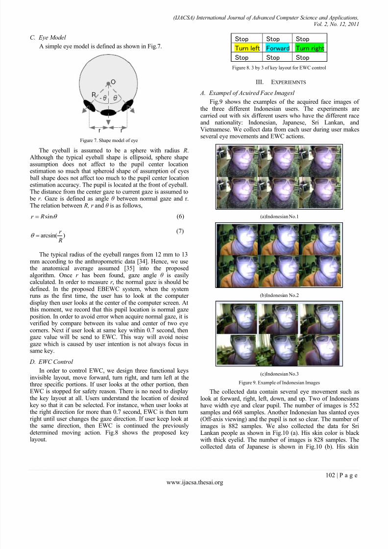
D. EWC Control
In order to control EWC, we design three functional keysinvisible layout, move forward, turn right, and turn left at the
three specific portions. If user looks at the other portion, thenEWC is stopped for safety reason. There is no need to displaythe key layout at all. Users understand the location of desiredkey so that it can be selected. For instance, when user looks atthe right direction for more than 0.7 second, EWC is then turnright until user changes the gaze direction. If user keep look atthe same direction, then EWC is continued the previouslydetermined moving action. Fig.8 shows the proposed keylayout.
Stop Stop Stop
Turn left Forward Turn right
Stop Stop Stop
Figure 8. 3 by 3 of key layout for EWC control
III. EXPERIEMNTS
A. Exampel of Acuired Face Imagesl Fig.9 shows the examples of the acquired face images of
the three different Indonesian users. The experiments arecarried out with six different users who have the different raceand nationality: Indonesian, Japanese, Sri Lankan, andVietnamese. We collect data from each user during user makesseveral eye movements and EWC actions.
(a)Indonesian No.1
(b)Indonesian No.2
(c)Indonesian No.3
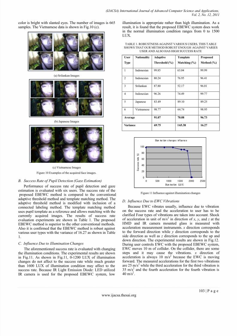
Figure 9. Example of Indonesian ImagesThe collected data contain several eye movement such as
look at forward, right, left, down, and up. Two of Indonesianshave width eye and clear pupil. The number of images is 552samples and 668 samples. Another Indonesian has slanted eyes(Off-axis viewing) and the pupil is not so clear. The number of images is 882 samples. We also collected the data for SriLankan people as shown in Fig.10 (a). His skin color is black with thick eyelid. The number of images is 828 samples. Thecollected data of Japanese is shown in Fig.10 (b). His skin
8/3/2019 Paper 15-Eyes Based Eletric Wheel Chair Control System
http://slidepdf.com/reader/full/paper-15-eyes-based-eletric-wheel-chair-control-system 6/8
(IJACSA) International Journal of Advanced Computer Science and Applications,Vol. 2, No. 12, 2011
103 | P a g e
www.ijacsa.thesai.org
color is bright with slanted eyes. The number of images is 665samples. The Vietnamese data is shown in Fig.10 (c).
(a) Srilankan Images
(b) Japanese Images
(c) Vietnamese Images
Figure 10 Examples of the acquired face images.
B. Success Rate of Pupil Detection (Gaze Estimation)
Performance of success rate of pupil detection and gazeestimation is evaluated with six users. The success rate of the
proposed EBEWC method is compared to the conventionaladaptive threshold method and template matching method. Theadaptive threshold method is modified with inclusion of aconnected labeling method. The template matching methoduses pupil template as a reference and allows matching with thecurrently acquired images. The results of success rateevaluation experiments are shown in Table 1. The proposedEBEWC method is superior to the other conventional methods.Also it is confirmed that the EBEWC method is robust againstvarious user types with the variance of 16.27 as shown in Table
1.
C. Influence Due to Illumination Changes
The aforementioned success rate is evaluated with changingthe illumination conditions. The experimental results are shownin Fig.11. As shown in Fig.11, 0-1200 LUX of illuminationchanges do not affect to the success rate while much greater than 1600 LUX of illumination condition may affect to thesuccess rate. Because IR Light Emission Diode: LED utilizedIR camera is used for the proposed EBEWC system, low
illumination is appropriate rather than high illumination. As aresult, it is found that the proposed EBEWC system does work in the normal illumination condition ranges from 0 to 1500LUX.
TABLE 1. ROBUSTNESS AGAINST VARIOUS USERS, THIS TABLESHOWS THAT OUR METHOD ROBUST ENOUGH AGAINST VARIES
USER AND ALSO HAS HIGH SUCCESS RATE
UserType
Nationality AdaptiveThreshold (%)
TemplateMatching (%)
ProposedMethod (%)
1 Indonesian 99.85 63.04 99.99
2 Indonesian 80.24 76.95 96.41
3 Srilankan 87.80 52.17 96.01
4 Indonesian 96.26 74.49 99.77
5 Japanese 83.49 89.10 89.25
6 Vietnamese 98.77 64.74 98.95
Average 91.07 70.08 96.73
Variance 69.75 165.38 16.27
Figure 11 Influence against illumination changes
D. Influence Due to EWC Vibrations
Because EWC vibrates usually, influence due to vibrationon the success rate and the acceleration to user has to beclarified Four types of vibrations are taken into account. Shock of acceleration in unit of m/s2 in direction of x, y, and z at theHMD and IR camera mounted glass is measured withacceleration measurement instruments. x direction correspondsto the forward direction while y direction corresponds to the
side direction as well as z direction corresponds to the up anddown direction. The experimental results are shown in Fig.12.During user controls EWC with the proposed EBEWC system,EWC moves 10 m of collider. On the collider, there are somesteps and it may cause the vibrations. x direction of acceleration is always 10 m/s2 because the EWC is movingforward. The measured accelerations for the first two vibrationsare 25 m/s2 while the third acceleration for the third vibration is35 m/s2 and the fourth acceleration for the fourth vibration is40 m/s
2.
Illumination changes influence
0
20
40
60
80
100
0 500 1000 1500 2000 2500
Illumination (LUX)
S
u c c e s s
r a t e
( % )
8/3/2019 Paper 15-Eyes Based Eletric Wheel Chair Control System
http://slidepdf.com/reader/full/paper-15-eyes-based-eletric-wheel-chair-control-system 7/8
(IJACSA) International Journal of Advanced Computer Science and Applications,Vol. 2, No. 12, 2011
104 | P a g e
www.ijacsa.thesai.org
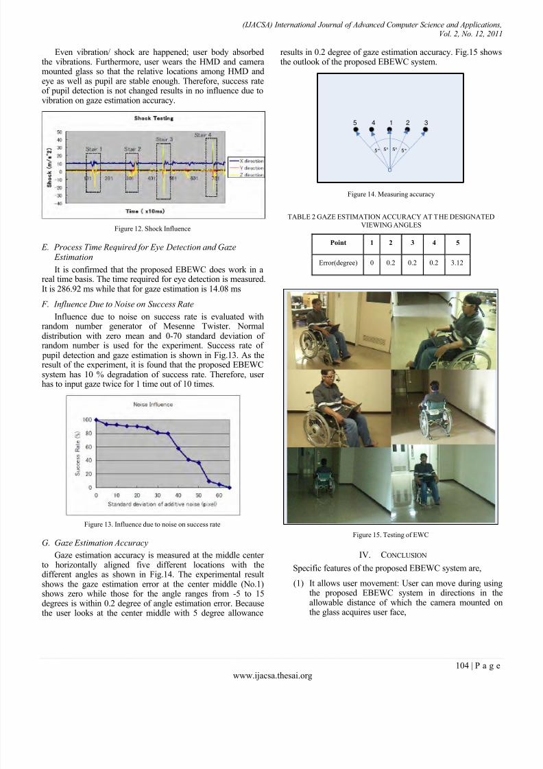
Even vibration/ shock are happened; user body absorbedthe vibrations. Furthermore, user wears the HMD and cameramounted glass so that the relative locations among HMD andeye as well as pupil are stable enough. Therefore, success rateof pupil detection is not changed results in no influence due tovibration on gaze estimation accuracy.
Figure 12. Shock Influence
E. Process Time Required for Eye Detection and Gaze Estimation
It is confirmed that the proposed EBEWC does work in areal time basis. The time required for eye detection is measured.It is 286.92 ms while that for gaze estimation is 14.08 ms
F. Influence Due to Noise on Success Rate
Influence due to noise on success rate is evaluated withrandom number generator of Mesenne Twister. Normaldistribution with zero mean and 0-70 standard deviation of random number is used for the experiment. Success rate of
pupil detection and gaze estimation is shown in Fig.13. As theresult of the experiment, it is found that the proposed EBEWCsystem has 10 % degradation of success rate. Therefore, user has to input gaze twice for 1 time out of 10 times.
Figure 13. Influence due to noise on success rate
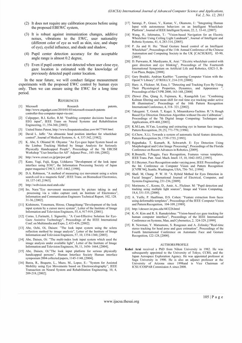
G. Gaze Estimation Accuracy
Gaze estimation accuracy is measured at the middle center to horizontally aligned five different locations with thedifferent angles as shown in Fig.14. The experimental resultshows the gaze estimation error at the center middle (No.1)shows zero while those for the angle ranges from -5 to 15degrees is within 0.2 degree of angle estimation error. Becausethe user looks at the center middle with 5 degree allowance
results in 0.2 degree of gaze estimation accuracy. Fig.15 showsthe outlook of the proposed EBEWC system.
Figure 14. Measuring accuracy
TABLE 2 GAZE ESTIMATION ACCURACY AT THE DESIGNATED
VIEWING ANGLES
Point 1 2 3 4 5
Error(degree) 0 0.2 0.2 0.2 3.12
Figure 15. Testing of EWC
IV. CONCLUSION
Specific features of the proposed EBEWC system are,
(1) It allows user movement: User can move during usingthe proposed EBEWC system in directions in theallowable distance of which the camera mounted onthe glass acquires user face,
1 2 345
5° 5° 5° 5°
8/3/2019 Paper 15-Eyes Based Eletric Wheel Chair Control System
http://slidepdf.com/reader/full/paper-15-eyes-based-eletric-wheel-chair-control-system 8/8
(IJACSA) International Journal of Advanced Computer Science and Applications,Vol. 2, No. 12, 2011
105 | P a g e
www.ijacsa.thesai.org
(2) It does not require any calibration process before usingthe proposed EBEWC system,
(3) It is robust against immunization changes, additivenoises, vibrations to the EWC, user nationality(different color of eye as well as skin, size, and shapeof eye), eyelid influence, and shade and shadow,
(4) Pupil center detection accuracy for the acceptable
angle range is almost 0.2 degree,(5) Even if pupil center is not detected when user close eye,
gaze location is estimated with the knowledge of previously detected pupil center location.
In the near future, we will conduct fatigue measurementexperiments with the proposed EWC control by human eyesonly. Then we can ensure using the EWC for a long time
period.
R EFERENCES
[1] Microsoft Research patents,http://www.engadget.com/2010/01/03/microsoft-research-patents
controller-free-computer-input-via-em/.
[2] Culpepper, B.J, Keller, R.M: "Enabling computer decisions based onEEG input", IEEE Trans on Neural Systems and RehabilitationEngineering, 11, 354-360, [2003].
[3] United States Patent, http://www.freepatentsonline.com/4677569.html.
[4] David L. Jaffe: "An ultrasonic head position interface for wheelchair control", Journal of Medical Systems, 6, 4, 337-342, [1982].
[5] K. Abe, S. Ohiamd M. Ohyama: ”An Eye-gaze Input System based onthe Limbus Tracking Method by Image Analysis for SeriouslyPhysically Handicapped People”, Proceedings of the 7th ERCIMWorkshop ”User Interface for All” Adjunct Proc., 185-186, [2002].
[6] http://www.creact.co.jp/jpn/por.pdf
[7] Kuno, Yagi, Fujii, Koga, Uchikawa ”Development of the look inputinterface using EOG”, the Information Processing Society of Japan
paper magazine C39C5, 1455-1462, [1998].
[8] D.A. Robinson, ”A method of measuring eye movement using a sclerasearch coil in a magnetic field”, IEEE Trans. on Biomedical Electronics,
10, 137-145, [1963].[9] http://webvision.med.utah.edu/
[10] Ito, Nara:”Eye movement measurement by picture taking in and processing via a video capture card, an Institute of Electronics”,Information and Communication Engineers Technical Report, 102, 128,31-36, [2002].
[11] Kishimoto, Yonemura, Hirose, Changchiang:”Development of the look input system by a cursor move system”, Letter of the Institute of ImageInformation and Television Engineers, 55, 6, 917-919, [2001].
[12] Corno, L.Farinetti, I. Signorile,: ”A Cost-Effective Solution for Eye-Gaze Assistive Technology”, Proceedings of the IEEE InternationalConf. on Multimedia and Expo, 2, 433-436, [2002].
[13] Abe, Ochi, Oi, Daisen: ”The look input system using the sclerareflection method by image analysis”, Letter of the Institute of ImageInformation and Television Engineers, 57, 10, 1354-1360, [2003].
[14]
Abe, Daisen, Oi: ”The multi-index look input system which used theimage analysis under available light”, Letter of the Institute of ImageInformation and Television Engineers, 58, 11, 1656- 1664, [2004].
[15] Abe, Daisen, Oi:”The look input platform for serious physicallyhandicapped persons”, Human Interface Society Human interfacesymposium 2004 collected papers, 1145-1148, [2004].
[16] Barea, R., Boquete, L., Mazo, M., Lopez, E.: ”System for AssistedMobility using Eye Movements based on Electrooculography”, IEEETransaction on Neural System and Rehabilitation Engineering, 10, 4,209-218, [2002].
[17] Sarangi, P., Grassi, V., Kumar, V., Okamoto, J.: ”Integrating HumanInput with autonomous behaviors on an Intelligent Wheelchair Platform”, Journal of IEEE Intelligent System, 22, 2, 33-41, [2007].
[18] Wang, H., Ishimatsu, T.: ”Vision-based Navigation for an ElectricWheelchair Using Ceiling Light Landmark”, Journal of Intelligent andRobotic Systems, 41, 4, 283-314, [2005].
[19] P. Jia and H. Hu: ”Head Gesture based control of an IntelligentWheelchair”, Proceedings of the 11th Annual Conference of the ChineseAutomation and Computing Society in the UK [CACSUK05], 85-90,[2005].
[20] D. Purwanto, R. Mardiyanto, K. Arai: ” Electric wheelchair control with
gaze direction and eye blinking”, Proceedings of The FourteenthInternational Symposium on Artificial Life and Robotics, GS21-5, B-Con Plaza, Beppu, [2008].
[21] Gary Bradski, Andrian Kaebler: ”Learning Computer Vision with theOpenCV Library”, O’REILLY, 214-219, [2008].
[22] Haro. A, Flickner. M, Essa, I: ”Detecting and Tracking Eyes By UsingTheir Physiological Properties, Dynamics, and Appearance ”,Proceedings of the CVPR 2000, 163-168, [2000]
[23] Zhiwei Zhu, Qiang Ji, Fujimura, K., Kuangchih Lee: ”CombiningKalman filtering and mean shift for real time eye tracking under activeIR illumination”, Proceedings of the 16th Pattern RecognitionInternational Conference, 4, 318- 321, [2002].
[24] Takegami. T, Gotoh. T, Kagei. S, Minamikawa-Tachino. R:”A Hough
Based Eye Direction Detection Algorithm without On-site Calibration”,Proceedings of the 7th Digital Image Computing: Techniques andApplications, 459-468, [2003].
[25] K.M.Lam, H.Yan, Locating and extracting eye in human face images,Pattern Recognition, 29, [5], 771-779, [1996].
[26] G.Chow, X.Li, Towards a system of automatic facial feature detection,
Pattern Recognition 26, 1739-1755, [1993].
[27] Rajpathaka. T, Kumarb, R, Schwartzb. E: Eye Detection UsingMorphological and Color Image Processing”, Proceedings of the FloridaConference on Recent Advances in Robotics, [2009].
[28] R.Brunelli, T.Poggio, Face Recognition, Features versus templates,IEEE Trans. Patt. Anal. Mach. Intell. 15, 10, 1042-1052, [1993].
[29] D.J.Beymer, Face Recognition under varying pose, IEEE Proceedings of the Int. Conference on Computer Vision and Pattern Recognition[CVPR’94], Seattle, Washington, USA, 756- 761, [1994]
[30] Shafi. M, Chung. P. W. H: ”A Hybrid Method for Eyes Detection inFacial Images”, International Journal of Electrical, Computer, and
Systems Engineering, 231-236, [2009].
[31] Morimoto, C., Koons, D., Amir, A., Flickner. M: ”Pupil detection andtracking using multiple light sources”, Image and Vision Computing,18,4, 331-335, [2000].
[32] A. Yuille, P. Haallinan, D.S. Cohen: ”Feature extraction from facesusing deformable templates”, Proceedings of the IEEE Computer Visionand Pattern Recognition, 104-109, [1989].
[33] http://citeseer.ist.psu.edu/443226.html
[34] K.-N. Kim and R. S. Ramakrishna: ”Vision-based eye gaze tracking for human computer interface”, Proceedings of the IEEE International
Conference on Systems, Man, and Cybernetics, 2, 324-329, [1999].
[35] R. Newman, Y. Matsumoto, S. Rougeaux and A. Zelinsky:”Real-timestereo tracking for head pose and gaze estimation”, Proceedings of theFourth International Conference on Automatic Face and GestureRecognition, 122-128, [2000].
AUTHORS PROFILE
Kohei Arai received a PhD from Nihon University in 1982. He wassubsequently appointed to the University of Tokyo, CCRS, and theJapan Aerospace Exploration Agency. He was appointed professor atSaga University in 1990. He is also an adjunct professor at theUniversity of Arizona since 1998and is Vice Chairman of ICSU/COSPAR Commission A since 2008.