PAP-17. - usbr.gov · position: and depth determinations is facilitated by the fix button, which is...
35
r g i PAP-17. oFF1 c F FILE COPY BUREAU OF RECLAMATION HYDRAULIC LABORATORY
Transcript of PAP-17. - usbr.gov · position: and depth determinations is facilitated by the fix button, which is...

r gi
PAP-17.
oFF1 c F
FILE COPY BUREAU OF RECLAMATION
HYDRAULIC LABORATORY
SUPS 50,N1C KETHUDS SHORT-CM h F B&M-M! SILT _Mf;A6 m-14 l 3
Charlene W. Thomas
Associate iiamber, 4SCE
Engineer, -bureau of keelamation
Denver, Colorado
The entire economy of the samiiarid weatern United States is dependent
upon reservoirs for water storage. Silt-laden rivers carry sediment in
a fi,azing quantities---two billion tons have been deposited in Head Lake
behind Hoover Data since 1.935—and this sediar.ent slowly but permanently
iL-,pairs reservoir ;storage capacity. ~)tudi*s of t-ie location : and extent
of deposits, and the zovem.ent of silt-carrying density currents within
them surely will extend the useful life of storage reservoirs. high-
frequency echo-soundin'; equipment is standard for depth measurevents,
and several electronic instruments are being tried out for coordinati.a}g
quickly the horizontal location of the soundings. After describinx,
conventional silt-survey equipment and procedures before the hydraulic
Division session in Qklahoua City, <r. Thomas cha len~,re enCineers to
develop supersonic sounding equipment further to measure depths of
silt directly as well. as explore the behavior of density curvents.

SUPzRSONIC 143 MODS SHORT-= RES~sYOIR SILT X&AS DMTS
Charles :4. Thomas
Associate ;,!ember, ASCE
Ehgineer, Bureau of Reclamation
Denver, Colorado.
Econoadc life of any water conservation or utilization project,
whether such project be for irrigation, flood control, navigation, power,
domestic water supply, or other use, is directly dependent upon the length
of time that the reservoir continues to fulfill the purpose for which it
was built--namely.. the storage of water. Reservoir sed1mentation must be
studied extensively In order to plan the proper location and operation of
outlets through the dart= and for the reduction of sediment accu ulation.
The Bureau. of LecluAtion has constructed approxirstely 80 storap
reservoirs since its inception as a Federal service. Operation of the
reservoirs is complicated because they r=ust serve multiple parposes by
storing water for irrigation and power and makin:, available additional
capacity for flood control.
After construction of a dani, changes occur in the strear. channel for
a considerable distance both upstreu: and downstrow f Corn the structure.
These changes may be caused by the departure from virgin conditions in
quantities of water released ;into the same channel, by a sirilar change
in the sediagnt content of the water released, by changes of velocities,
by coDbination of these .factors, or by deposition in backwater areas. The
results Of these changes may be to increase drainage difficulties, increase
the head on pua~,ing plants, cause excessive scour around existing structureaw,
excessive deposition around river developments, or other effects due to
changes in strea;~: regimen.

HALE` Of SILT IN UPP h HALF OF RiMRV IR
A study of the reservoir surveys conducted to date has permitted
the deteru:ination of the location of the sediment deposits within
eervoirs. This is important frow rany standpoints, particularly with
r*X*rd to planning aspects. It has been found that W percent of the
sediment its Guernsey Rovervoir, Wyouing, is deposited in the upper
35 percent of the reservoir depth, calculated fro spillway level. This
reservoir is operated so that the reservoir pool is held nearly constant
during the irrigation season, In Eoosevelt Reservoir, Arizona, Mich
operates over wide variations in pool elevation, only 30 percent of the
sediment is deposited in the upper 35 percent of the depth. In contrast
to these two reservoirs is the deposit in Elephant Butte heservoir,
Now Iilexico, where approxix;atel;y %) piresnt of the sedimentss are found in
the upper 25 percent of the reservoir depth. This reservoir also has
considerable variation in the operating levels.
The most important conclusion to be drawn, from these studies is
that i._i all cases so far studied irz the }pest, over 5C percent of the
sediment deposits lie in the upper half of the reservoir. Inasmuch as
allocations for sediment storage in reservoirs have normall3r beep: placed
at the bottom of the reservoirs, it seer=s advisable to question contin—
uation of the practice of allowing relatively large mounts of dread
storage that will not be filled with sediment for many years.
Conversely, it has usually been considered that the upper levels of
reservoirs, usually allocated to flood control in multipurpose protects,
would be free Prot. sediment deposits. rata so far collected show that
2
in some cases this "otion of the reservoir may Abe subject to the
greatest amount, of sediment: d*yrovi,tion. These fmats should siter our
planning of mteorvoirs# partica.Urly those intended for multipl -purpoaa
open-OktLon.
5u *ys of sediment deposits -.v-*t~ be ad*Watoly planned its order that
they raj furni*b a as h of Information front which to calculates the lon; th
of 'titers required for the bed;i nt. to raacmulate to the extent of impairing
or ondlog the useful We of the ros,er. ir. The watt location of this
sediment with regard to the dan thus beccv,es important.
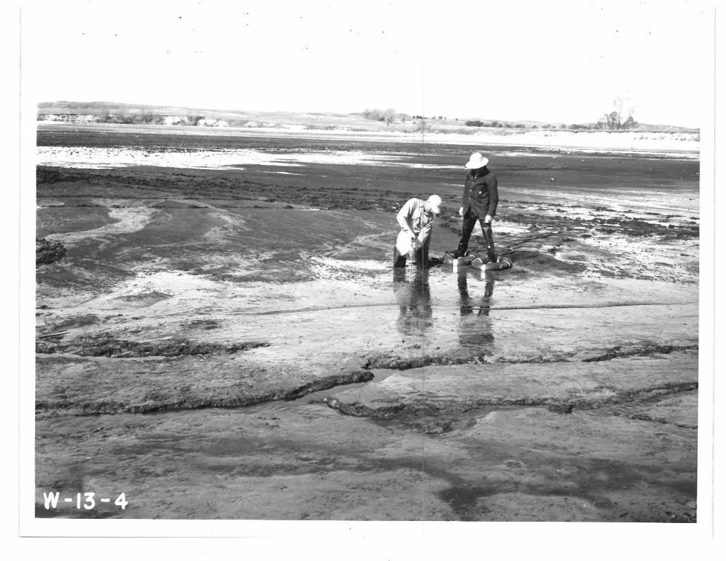
For that portion a1 the saws lying atevas the water ourfac* existing
at the tile, L4P survey Vii. ocedu» e Is AW.ar to that followed in the
conduct of * rdinary toMraphic dst+eminationoo Some a i.fi.aection in
a:+ethodA &W +equiprentt used is iwe*ssaary to penetrate share-dine vegetation
and to nogotiats sad flat*.
That portions of the reservoir below the existing water surface is
not resdiily aocessible. The usual prooed.urs in this csse its to explaj,
hydrographic ~u.,vey "t.hodr, ydro~ rsphi.c survey* are thre s disetenaiotae ..
i sourdine. reprosente a vortical dUwnsian downward fm4, the crater surface
to Vie baths;.: of the reservoir, Thias sound3nz ; ausA be located to the
horizontal plans by two coord"too. ne*,, in addition to tba $*=d: g*
there must also be horizontal control of the survey,
In large rss osrvoi.res soundings are rd* along predetsem4ned aodimeenU—
tior: "ranges" or reservoir *room—sectl.on lines. 4h+are practicabl e,e these
ranges are located morns, to the streat, flow and the valley,* and sp*ood
so thRt the ave raga etA areas of adjacent rangers are representativ* of
3

the section b; town them. Ranges are located across the mouths of all
principAl arms of the reservoir, and the range network should extend UqP
these tributaries in a zann*r similar to that on the main stress, The
ends of each range are perrarmntly &ark*d, and all ranges should be tied
together by an active triangulation network expanded Atm a chained and
chocked basso-line. In small reservoirs these rangge zay be spaced
sufficiently close so that bottom contours can be drawn. In some reser-
Mrs when it is desired to develop bottom contours,ranges mis,ht be
dispensed with and independent sounding surveys made.
One of the two major factors inxolvvd in the hydrographic survey
Is obtaining the soundings. These are made in shallow water depth by
means of a sounding pole with a baseplate. The general practice for
measuring greater depths. has beeno until the past few years, to take
soundings by conventional lead-line methods, or by some mechanical
device. A rope, lead line, hold in the hand, or a piano mire on a
rounding wheel have been used, and can still he used to advantage under
certaiR circumstances. However, the more modern supersonic echo-sounding
equipment is now more generally utilized.
Krizontal control of reservoir sedimentation surveys ray be
accomplished by utilizing two ger*ral classes of equipwant: (1) plwai-
metric survey and navigation instruments and (2) electronic equipment.
The first method is now used almost exclusively, while the latter method
has been used in coastal and land surveys and could be adapted to reser-
voirs. The possibility of using photogrammetry has bee- considered, but,
to date, no practical application has teen made.

When range lines are used, the problem resolves itself into
locating the survey craft as it progresses along there. Coordinating
position: and depth determinations is facilitated by the fix button, which
is an integral part of the echo—sounding equipment. Each time- this button
is depressed, a permanent mark is made on the sounding chart. These fix
marks are identified by numbers. The graft is kept on the range line
by the operator, who liners up objects on shore, or by a transitman
stationed at one and of the range line who signals the helmeuAn when
deviations from course occur.
The following methods employing optical and mechanical equipment
have been used successfully to a scamplish the horizontal cor-troll, but
are dependent upon visibility frorr, shore to survey drafts
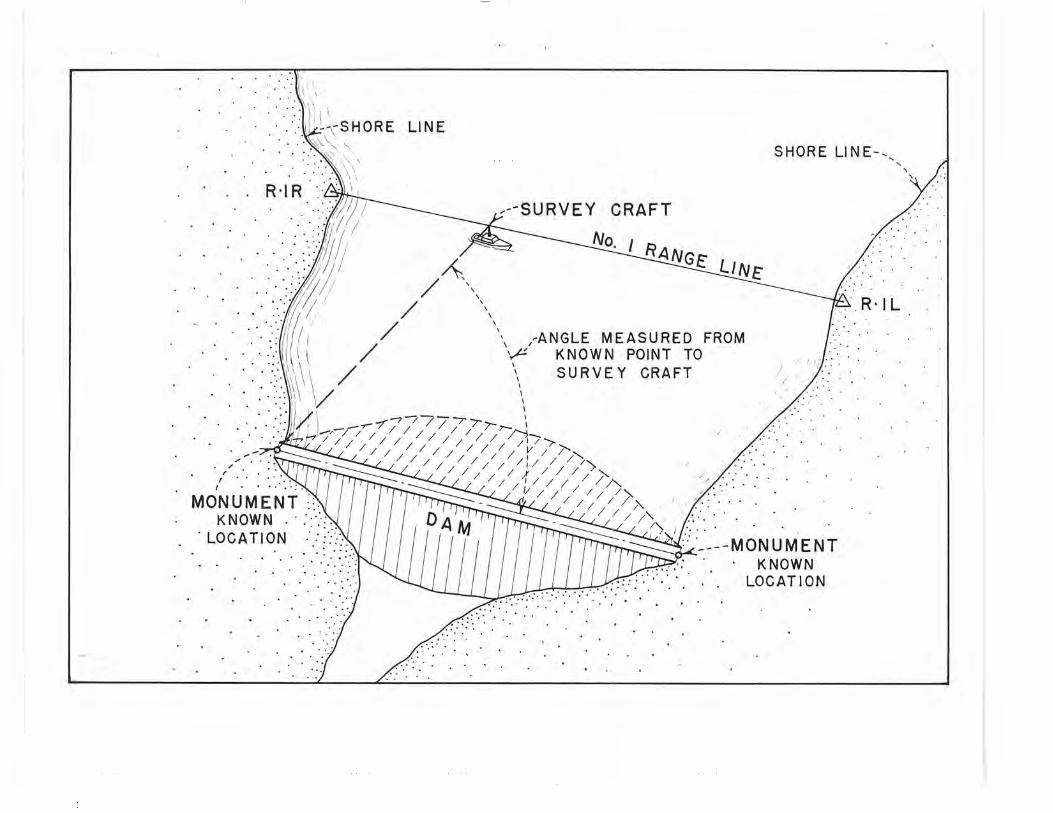
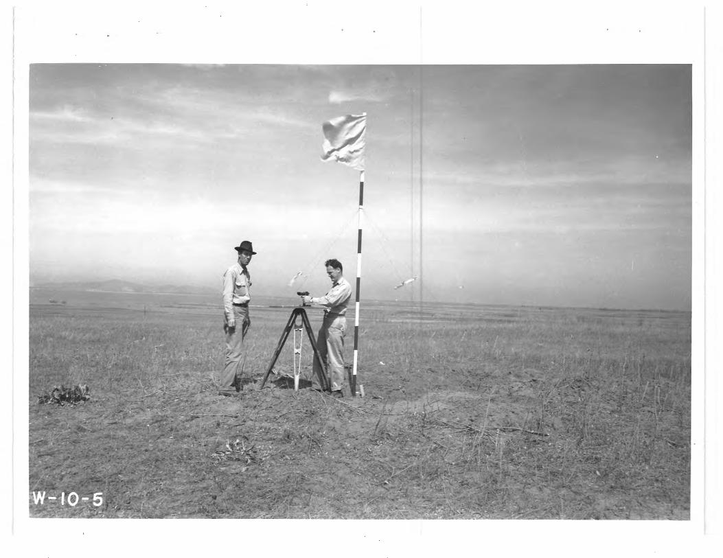
One or more transits are set up on share, at suitably situated
and accurately located triangulation stations, and the an;,~les from
known geographic loeGati.ons to the survey craft are read at the instru—
ment or instruments. The angle or angles Brea read periodically, and
a voice, radio, or flag signal is transruitted to the survey craft at
the exact inst-nt that the 'Measurerce►nt is made so the fix may be
recorded on the sounder chart. This method gives quite accurate results
but necessitates trained instrumentmen and sme means of boat-to-shore,
coz u nication. Notes must be kept both on the craft and on shore and
these must be coordinated frequently.
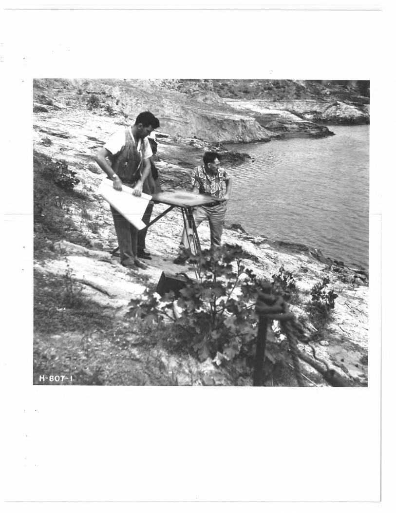
Another method of usin ~ intersection to deterai.ine the position
of the survey craft on the range line is to :mare use oil' the alidade

and planetable. One or more planetablexas are located on shore at
carefully located points, and the angle botween aso known point on shore
and the survey craft is determined graphically. This method gives
results slightly lease accurate than the use of transits.
A method of resectio.- is used to determine the position of the
craft on the range line by reading,the angle betwo*n two points on
shore with a sextant located can they surrey craft. The: monuments, or
m ints or shore, mst be acou:rate:l.y located. This is a seimrl.+e, accurate
Liethod and does not necessitate cozwani.cati b*t^r en the beat aid the
share except to keep the survey boat on the range line. Since the
angles are read at or near the sounder, notes may be wade directly
on the recording.(he man on the boat can operate a sextant with
a sl+ all, a-mount of' qpecial training,
Piano wires on a calibrated reel, is used to reaMsuree the distance
fro=g: the boat to a known paint on land as the b*at proceeds aloe
the range line &*rose the reservoir. This method, which requires
only a calibrated reel, for the wire, has the advantage of being; used
and read: on. the craft. The silt range roc rent and the shore anchor
for the wire must be accurately located. The brat is kept or, the silt
range line by range Darkens or by instrumentswi. Floats attached to
the wire at intervals keep it on the mater surface wA hanese in a
horizontal. position. Distances up to one mile j~iy be measured in this
manner without appreciable error.
A calibraated, price-tom current Beater is used to weasure distance
along the range line. The meter is suspended In the water and the
MV

revolutions of the bucket wheel counted electrically as the moat
proceeds. From data read on the calibration curves for the meter,
the distar. ;e traveled rna., be calculated.
Where: it is desired to study the deposition of material brought
in by tributaries :and deposited an a delta, or to determd.n;e accurate
bottom m contours, a piano wire in fastened to an anchor on share and
the stmt is coved in arcs about this point as a Rauh. ~rces of 25 or
50 feet in radius are ordinarily used. The locations of the boat or
the are is deter _i..ed b.-r the trarxsit or al.idade and planetables.
There are a iiumber of n:etho?ds of horizontal control that employ
electronic equipment. Some of this equipr ent ha-- bew used In raking
hydrogrraphic surveys, and the=_ra is other equipment that, may 00 applicable
to hydrographic surveys o re-ervoir sediresntatioy. surveys. Z-% brief
description of the= eq iphient and the sa.ethod o:' operationn, of a few of these
electronic devices follows: :
the: Shoran n,eethod wa,s develoFed for precision control of air-
borne aircraft on boubing rkiescions duriAg the war. Two laird stations
could control a number of air-borne stations aboard the bombers. The
Coast and Geodetic Survey has successfully used this egaxipaae>at in
conducting off-shore surveys In both the Atlantic and the Pacific
Ueeans. Two accuratel.;. located shore stations and one station on the
craft are needed. The; station on the craft radiates pulses i, alternate
groups at two different carrier frequencies nciees of very short wave lengAh.
7
One of the share stations is tuned to one carrier frequency and
the ether station to the reuaainina frequency.
reception of the pulse from the aircraft causes a yround
station to act as a transponder and relay a pulse ore a different
frequency back to the craft where it Is received and displayed and
the distaanc* to the station recorded. The equipment consists of very
compact and tall-built components, and the accuracy is very good for
long; distances, but the percentage of error is greater .for short
distances. This is due to equipwent errors. ~atimated probable
error with =modified Shoran equipment is +50 feet rsga,rdl.e s* ry e
distance.
The Carps of 4ngineer, Department of the Army, has experiweentead
with the use of XR-584 radar systeea in Galveston harbor. Positioning
of soundings in this harbor had been accomyl.i:sheed, previously, by
means of two saxtant angles read aboard the survey boat between
prominent landn,,arkee on the shore. An effort to spsad up this meathod
by means of a sextant angle grid was a definite i:..provert*nt, but the
fact, that the work could be delayed by bf#A weather and poor visibility
was ax.other difficulty that had to be overcome. The mobile radar unit
SC.-584 consists of a large truck-mounted steel van with all equipment
and controls inside. The antenna, located on the roof of the van,
will automatically position on a ship and track it. .eadings for
range and azimuth are obtained from dials. A small telescope is
mounted or., the antenna and may be used to assist in the initial
orientation of the unit. The operating power is furnished by a portable
generator. M.
For the Galveston surveys a responder was mounted on the survey
craft to assist the antenna in tracking the survey boat. Ship-to-shore
radio contact was z-tintainod for supervision of the vvrk. The results
of the experiment showed that a greater error -existed in the data from
the-measureu4nt of the angle than ir, the distance measurezent. The
distance zeasurements were obtained with an error of +6 fe*t for the
best results.
A system known as Raydist,, developed by the Hastings Instrwhent
Company, Hampton, Virginia, for wartime use, has since undergone inter.-
sive developr:ent as a means of surveying over water or, mouth terrair,
and as a precise tavigaticni and tracking system. In these applications
the i-aydist systevt results in high accuracy with the use of light and
simple apparatus. Raydist is a continuous wave system and depends o:,,
the reln-tivo phase relationship betweer-, continuous wave radio
transmitters.
Prob4bln the beat application of thir equipment for sedimentation
surveys is to use it as a pure range. system. Orly two instriments are
- . required,, and a continuous indication of the distance betw-ee-.: the two
sets is obtained. If one instriment were located at the end of the
range line and a recording instru",nt carried in the survey O"afti, cars -
tinuous indication of distance aloni- the line could be bad, "'Squiprent
of this type built for the Navy has been put in operatioi., and consis-uently
repeated measurev*nts within 2 feet on 'the indiwAor-e and 5 feet on the
recorders have boor. obtained. These errors were obtained In distances
of approximately 6 rdles. The eTc zip ment rray be coij;,letely housed in
W
suitcas*-type cabinets, the heaviest single unit weighing approxizately
32 pounds. Equipikent, necessary for the horisontal control of a **(U-
atentation survey would probably cost in the neighborhood of 420,,OW
at the present time, but this amount should be sonowhat reduced after
*.%et needs are known and production of the equipment increases,
Lora*.. or "long-range accuracy,* developed by the ismor graph
Service Corporation) to amother radio suryeying systm-r., operating on
iredium frequencies and mwdium wsve lengths. The uso of medim. frRquencles
and low voltages eauswp the equipment to be loss susceptible to ooraon
electrical problems that give trouble In high-frequomy, high-voltage
systems and does not tonfine its use to line-of-sight operation. In
this oyster three short stations and one boat installation are required.
The boat installation is quite small., and the for rvrtion may be
aounted in an out-of-the-way position.
The three lend statiorto are bulk-y and presently used squip,4snt
is not easily moved. This characteristic would be a disadvantase in
sedimentation surveys in that when. the Purvey moved froir one portion
of a la"s lake to anothor., it would probably be necessary to move
the shore equipment. The average repentaVility error in distance$
up to 9-1/2 miles has been found to be about 2-1/2 to 3 feet.
KWIMAM FOR VMAAL SILT-WRVEY PARTY
The equipment now employed by the Bureau of i4eclawation is designed
to provide omplete moVility, since the reservoirs are separated geograph-
ically. This separation distance may be a few miles or several hundred
miles. The prime mover consists of as 1-1/2-ton,, 4-whoel drive, Dodge
10

power wagon equipped with racks and hitches for carrying the survey
equipment and towing the survey boat and trailer. This vehicle has
adequate power to traverse rough terrain and will develop satisfactory
speed for movin . frou, one lake to another without undue delay. A station
wagon is also wr pl dyed to carry instruxonts and p< rs o nnel. and to serve as
a utility vehicle on the job.
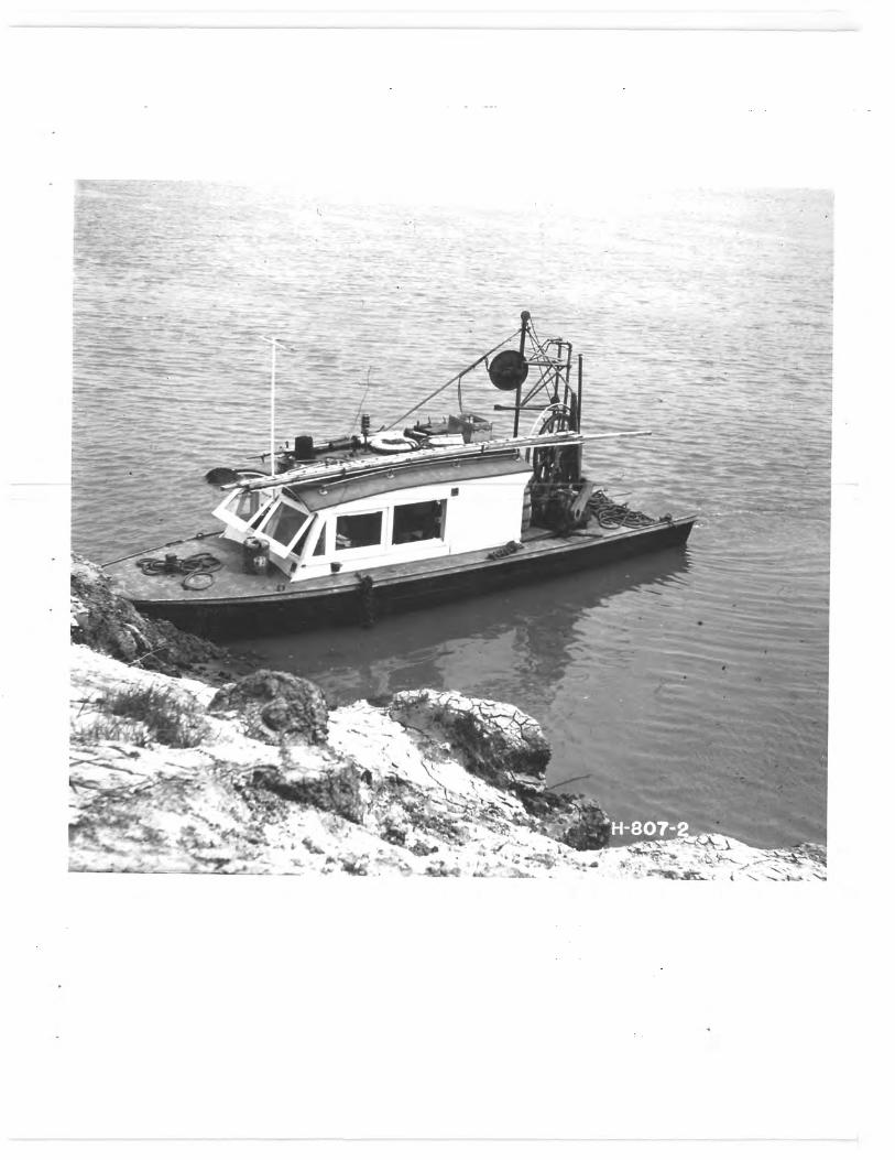
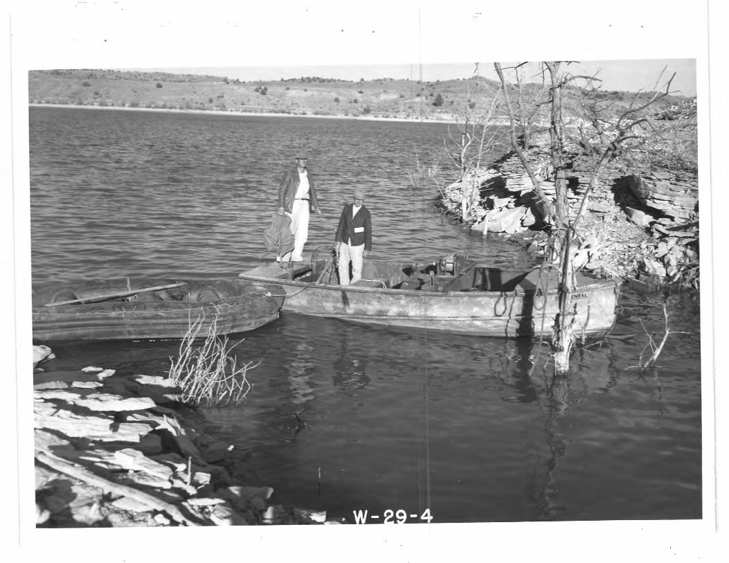
Are 18-foot boat with a 6-Moot -inch beau: is used for t.:* underwater
survey. This craft is of the open type, has a; plywood hull., and is
powered by a 52.--horsepower Inboard gasoline engine. The, boat has ample
space for a fives arena. O s set of asst>illators -f-Ortive supersonic
echo-sounding equipment is permanently installed i^ the hull of the
craft, and brackets are provided for outboard mounting of a separate
pair of oscillators. t small boat equipped with a--. outboard .motor is
used for obtainin;;,he soundings in shallow water.
A two eel trailer capable of caM-ing the brut at reasonable
speed on the highway is provided. This trailer is backed into the water
for loading; and unloading.
The supersonic echo-sounding equipment being used is a Submarine
Signal Cospany Model 808-J. As previously mentioned,, both inboard and
outboard oscillators have been provided with this wounding scluipment.
xperienoi has shown that the outboard oscillators Eive a better-definod
record than the oscillators installed in the hull of the: boat. This may
be due to the .Pact that the, hull is not of iiodel dimensions. The sounding
equipment is of the portable type and 33 not installed perrmnentlj in
11

the survey craft. An NK-2 adodel sounder aseanufactur•ed by Bloodworth
Marine Cookpany is rraintained in the laboratory in working order as
standby equipxent.
A very ussful piece of equipaeteent for the party has provod to be
walky-talky radios. This means of comunio tion enables the boat party
and the ins33tru►eaentmen on shore to maintain conversational. contact with
one another, thereby reducing hand signals and idisunderstanding. The:
equipuaeent used is forwor Army Signatl. Corps radio receivers and trans-
mitters and is operated on the frequencies assi.c-need to the Dureau of
«ecl.azation. - These radios are used to supplement the--wi alv sent and
received betws,*N, the beat and shore parties and to check they data as
taken.
The hydrographic party for the seedirw.ntation investigations consists
of frc»: three to rive: men specially trained for their duties in this
particular kind of work. Sine* the boat crew also does the above-crater
surveys, it is neceessaRry in r,o:kt inFUncess to suprIeveent the crews with
personnel obtained locally or borrowed froz Nearby pro jscts. It is
desirable for the recorder operator, or Some: other .,:art ir: the party, to
have son>e kn Pledgee of radio and electronic circaits in order to mAi.ntair:
the supersonic echo-solmdini: eaui rent, the radios, and r th..r slectri.c&I
devices used by the party.
In a3 number of the suz•veys the water sxi- face of they lake Varied
considerably during, the tire tote surveys were being m adc. In these
instances it was necessary to supplant th(-; so;md!nn- charts at oach end
of the ranges by land surveying. "his surveyir , * was done In the aonventicnal
12
method by use; transit, rod, and level, or alidade and rod. 1~o
significant differences were noted between the profiles obtained by the
conventional methods and those obtained by the use of the echo sounder
where they overlapped. In many instances profiles =mere intentionally
overlapped to provide a check. Since the lake stage usually fluctuates
during the period in which the survey is in progress, nurBrous check
readings may be nade using both methods on the saves portion of the reser-
voir cross-sections.
NAVY ODOMATIS IN LAZE MEAD SMVEY
A silt survey is now being conducted on Lake Read above: ,ioaver Slam.
`11iis survey, is being esarried out under a cooperative agreement by the
navy, the Bureau of ILeclamaticn, and the Geological :xurvey. Preliminary
reports indicate that in the 13 years since completion of Hoover Dam,
sedimentation deposits ranging, in depth frov; as little as 4 feet in the
Virgin iver arm of the lake to as much as 260 feet in the Colorado river
am have accumulated in the lake. With the rate of Colorado River deposits
averaging 400.,000 tons per day, a total of about two billion tons have
been deposited in the lake to date.
The experiences of the Bureau of Reclamation have shown that echo-
sounding equipment provides a rapid and accurate meads of conducting the
underwater portion of the reservoir sedimentation surveys. Caution gust
be exercised it the use of the equipment near the faces of` dams, against
steep cliffs, in swiftly flowing water, and in grater containing air in any
noticeable quantity. Frequent bar checks of the equipment will insure
that the necessary constants have been correctly applied.
13
DE =P SUPcxR IG &UIPMMT FLMTHER
Although the results of the sedimentation surveys conducted to date
have been quite satisfactory, engineers should not be satisfied that the
ultimate has been reached, but should be always on the alert for possibil-
ities of further advances either by way of electronics or by extended
application of the present equipment. Thinking along* these limes, it
appears possible that the supersonic echo-sounding equipment now used to
obtain the top of the sediment deposit in the reservoir may also be used
to measure the depth of the deposit in the reservoir directly.
It is also possible that this echo-sounding equipment may be used
for detecting and measuring depth and extent of density cuxxenta in a
reservoir such a Locke mead. If so, it would provide a rapid and, economi-
cal means: of measuring and plotting these currents. Once the behavior
of this phenop enon is understood, selected operation of gate$ and sluices
might permit passaage of considerable sediment through the eves. These
potential uses of the instrmeent in question have bee=., considered, and a
limited amount of work has beer. done to determine their adequacy for
such surveys.
In Elephant Butte Reservoir a reecurding was made on one range, and
a series of spot tests was made to coordinate the nvl.tiple echoes of the
echo sounder Ifith the results shown by sampling of the sediment with a
spud. The spud is a rod equipped with cups designed for taking samples
at different levels in the sediment. The spud used was only 10 feet long
and did not penetrate the old button, in all cases. Inspection of the
spud samples showeed layers of silt that corresponded to the reflection
14

surfaces in the recording. However, in one area of the reservoir, only
one surface was recorded by the echo sounder, and the spud teat showed
about & Peet of sediment above the old original bottor. It was assumed
from this that there was no penetration of the sound energy into the
sediment. This may have beer due to baking of the surface during the
low water period in the past. The results of the meager experimentation
are not conclusive, but some indications have been found fro, the serzall
amount or data taken. Fvidence from these and associated studies shown
that a different frequency of the supersonic wave will have a different
penetration into the soil or milt layer. The €08-J Submarine Signal
Company echo-sounding equipment operates at approximately 21 kilocycles
per second. The NK 2 Bloodworth 4arine equipment operates at approximately
14 kilocycles. The Bendix aviation Corporation is now building equipment
that operates at about 40 kilocycles per second. It appears that the
nigher Frequency equipment has a s13.-;htly better definition in the study
of either silt layers or density currents. It is proposed to use the
equipment having; the 'three different frequencies to obtain comparatives
recordings, from which the optimua frecuency for probing the sediment
deposits might be indicated., or an instrument developed for the purpose
whenever a conwehensive study of deposits might be initiated.
The overall s agnitude of reservoir sedimentation determinations, is
such that it merits the concerted cooperative efforts of all concerned,
even to the Joint purchase and developfi:ent of equipment. There is a
definite need for an accurate, continuous mews of position finding as
well as a wider adaptation for the use of the present sounding equipment.
15

SPILLWAY ELEVATION OR -•~ 1 90
BOTTOM OF FLOOD STORAGE
71.E ►6:i /
32;3 .~• ~•~~/
•••• • 1
80
N t ~ PVAP
lool
.~~
w /• Gv ••.•• 3$.i••3~
.
'• /""
cr 60
lee
0, 0 50 • /
1~ • ~~_0~ "
w w
/ /
% '• v 0 i w /~
~~ i 0 /
+ 5 ♦/"
w 40 ' Or i o
X. w
.•''•• -'~ 'LYLENGTH OF RECORD
wLOSS OF CAPACITY-% Moe 30 •.
20 : •~
f / /. LOCATION OF SEDIMENT DEPOSITS
10 0.1"
• PERCENT OF TOTAL SEDIMENT DEPOSIT 10 20 30 40 50 60 70 80 90

kt
Pee ,
k.

ice" t vw
y., -~ 1'
x',1
1`,
~~~ i
~; ~
• ,:
°. ~ ~~. ,.:,:
';,~, sr'
l u'
'~
w
}
t
JJ ~
1. r
1
t r
1 2
a i
a
f 1'1
1~
■9
S~
.

4's
R

2219
R ~ C Le 2R a
R'2/4 ,--DA M
c1 ~~ J? R.~p~ R
ra
R 1- 64
/ ~., ~~ p 2R
~•
R•5L / R•
-5
Ln
~ ~ \\
i p~R R•30 R' 2000 0 2000 4000 6000
R•30L i~ R- 30R
SCALE OF FEET
R• 5R ~I 1
R•31L ~ R,31R SEDIMIENT RANGES
i'' -'-SHORE LINE
SHORE LINE
R•IR ;%/' i' ---SURVEY CRAFT
/ . R'IL
:: ~ -ANGLE MEASURED FROM KNOWN POINT TO SURVEY CRAFT
//
MONUMENT KNOWN D,q
LOCATION :. M /\~~I ~• ---MONUMENT
KNOWN LOCATION

-SHORE LINE
SHORE LINE
R•IR -SURVEY CRAFT
RQNCE LINE i
~ / l R I L _ ___ • ' : • '~'// ~ -- ANGLE MEASURED
' Y SEXTANT i1,`, (~ '~----- ON CRAFT
MONUMENT• KNOWN DAM \ ~/
LOCATION ~_ --MONUMENT KNOWN
' LOCATION
WM6 +tom;►
~~~ ti r, a

SHORE RELAY STATION
(FIXED) SHORE RELAY STATION
(FIXED)
IMPULSE FROM MOBILE STATION RELAYED BACK TO SHIP FROM SHORE STATION ----------
MOBILE STATION SENDING, RECEIVING
AND RECORDING
SHORAN METHOD FOR
DETERMINING POSITION

F TARGET
HORIZONTAL , DISTANCE TO TARGET
REFERENCE I~II (SLANT RANGE)
LINE I ~l i ,-ANGLE OF ELEVATION
NORT
REFLECTOR-
ANTENNA -- ,-ELEVATOR
AZIMUTH ANGLE
V~
BASIC PRINCIPLES OF OPERATION - - AZIMUTH
SELSYN
—PEDESTAL IN RAISED POSITION PEDESTAL
MOBILE UNIT
lk Al b ~ 'l,

CENTRAL F LORAC TRANSMITTER SYSTEM
CITY
I /0/
20/
90
30
40 8
/ ,MOBILES // 40 70
~ V "RECEIVER\ 2
50
50 70 60 60
RESET 00 0
80 5 4 20
i
60 40
RED PHASE METER
r0
`20
80 30 O
RE
C~"
'
'
GREEN PHASE METER

rk 2`'{r
,i ~r
Y yY
,
'Tiff It W
417, 17
1 1'Im
t' ^~
,
G ~
r
1 p
~
•~.i ~
1t~
,r'~
't ~
~ ~
~ µ
X41
ti l Jj
+~ iQ
v

). CHART 1~'l' WWWr SUBMARINE 5;, NAL CO. CHART F'.' )
- - - -
Fix No. 5 12.23 y FiX Ab. 4 /P:P/ -- J Fix No (3)12:/9 Fix N,.012-17 _-- - /— Fix No-- __--
R .... f
/ Bepwnwp of ,gun Scoe B ~Scob ALAMOCITA, 66-E
OirecJion of Ron Q12.15 F, M. A~ -.....v-='iGNAL CO
cops OA -
_. A- \ ' 1
1791235 1; :R3
Probable 00,1M of Sedimen7 _. _
- ..
'Z .e Double ECho i . +_ —_ t
- ~.
Hard Cake BoJJ[m
-LLI i
Fix ,
Fix 12:37 P.M.
-
Fix No. ll 12.35 - _- Fix No. (10/12:33+—
/ -- fix No. 9 /P•3l _! Fix No.( 12.' T
T 29 E .11 e A Sco e A Scole B TERRA PUB I 69-W
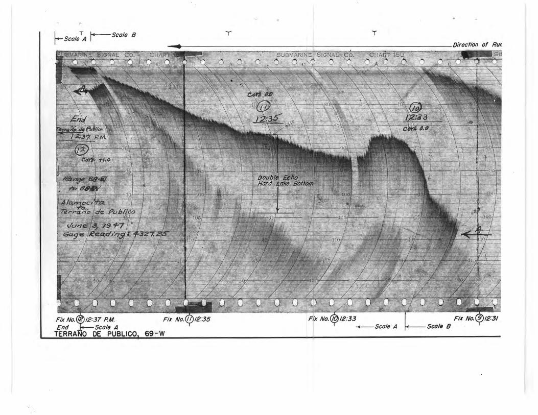
T — Scale B Scale A
BMARNE t7IGNAL CC% CHART
'r T
Direction of Rui
SUSNIARf? E SIGNAL Goo C E !A 15U SU .' . , .. ..
t, \
{ 0 2~
Double Echo g Hord Lake Bottom
T¢rrQ Q i aye hu.F. lico _ —105 — ur,
clLIWer ./9 9-7 Y
10
45
f
Fix No. / 12:37 P.M. Fix No. ll 1235 Fix No. 12:33 Fix
End Scale A T Scale A Scale B fERRANO DE PUBLICO, 69-W