PANTHER HP SERIES OIL PUMPS 3:1 Model #1130-015 Bare · PDF file3:1 Model #1130-015 Bare Pump...
16
Thoroughly read and understand this manual before installing, operating or servicing this equipment. OPERATION, INSTALLATION, MAINTENANCE AND REPAIR GUIDE SERVICE BULLETIN SB1064 Rev. O 02/09 PANTHER ® HP SERIES OIL PUMPS 3:1 Model #1130-015 Bare Pump #1130-017 Flange Mount 5:1 Model #1130-016 Bare Pump #1130-018 Flange Mount ®
Transcript of PANTHER HP SERIES OIL PUMPS 3:1 Model #1130-015 Bare · PDF file3:1 Model #1130-015 Bare Pump...

Thoroughly read and understand this manual before installing, operating or servicing this equipment.
OPERATION, INSTALLATION,MAINTENANCE AND REPAIR GUIDE
SERVICE BULLETIN SB1064Rev. O 02/09
PANTHER® HP SERIES OIL PUMPS3:1 Model #1130-015 Bare Pump
#1130-017 Flange Mount 5:1 Model #1130-016 Bare Pump
#1130-018 Flange Mount
®

2
General SafetyThoroughly read and understand this manual before installing, operating or servicing the described products.
WARNING DANGER: Not for use with fluids that have a flash point be low 100°F (38°C). Examples: g a s o l i n e , a l c o h o l . Sparking could result in an explosion which could result in death.
Because this pump can be incorporated into a pressurized systems, the following safety precautions should be observed.
Check equipment regularly and repair or replace worn and damaged parts.
Never alter or modify any parts of this pump, doing so may cause damage to pump and/or personal injury.
Under no circumstances should the dispensing valve be aimed at any person at any time. Personal injury may result.
Release pressures built up in the system before any service or repair is begun. See the pressure relief procedure below.
Do not operate this pump above 150 PSI (10.3 BAR) air inlet pressure or 200 cycles per minute.
Always read and follow the fluid manufacturer’s recommendations regarding the use of protective eye wear, clothing and respirators.
IMPORTANT
Pressure Relief Procedure:
Follow this procedure whenever you shut off the pump, when checking or servicing any part of the system and when installing, cleaning or changing any part of the system.
1) Disconnect the air to the pump.2) Point dispensing valve away from yourself and others.3) Open dispensing valve until pressure is relieved.
WARNING!
WARNING! THIS PUMP CONTAINS ALUMINUM AND ZINC PARTS. DO NOT use 1-1-1 Trichloroethane, methylene chloride or other halogenated hydrocarbon solvents or fluids containing such solvents in this pump. Use of these solvents/fluids may result in a violent chemical reaction, causing serious bodily injury, property damage or death. All fluids used in this pump must be chemically compatible with the wetted parts materials shown on page two (2) of this manual. Consult your chemical supplier to ensure compatibility.
WARNING! WARNING: Panther® 3:1 pump (1130-015) develops 375 psi (26 Bar) maximum working pressure and the Panther 5:1 pump (1130-016) develops 625 psi (43.1 Bar) maximum working pressure at 125 psi (8.6 Bar) maximum inlet air pressure and stall conditions. Be sure that any components or accessories used in the system are rated to withstand this pressure. To determine fluid output pressure at stall conditions, multiply the ratio of the pump by the air pressure being used.EXAMPLE: 5:1 Pump Ratio x 100 psi air pressure = 500 psi fluid pressure at stall.
In the presence of explosive vapors, take action to prevent static sparking. Failure to ground the pump, piping, valves, containers, or other miscellaneous equipment can result in fire or explosion. A green grounding lug is provided on the pump.
WARNING
If a check valve is installed at the end of the suction tube, then an external pressure relief valve must be installed at the outlet of the pump.
WARNING!

3
Table of ContentsCover .............................................................. 1General Safety Information............................. 2Product Description ........................................ 3Technical Data ................................................ 3Pump Installation ............................................ 4Preventive Maintenance ................................. 4Operation ........................................................ 5
Product DescriptionThe 3:1 ratio Panther® pump can service as many as three dispense points at up to 500 feet. The 5:1 ratio Panther® pump is suitable for simultaneous fluid distribution of up to two dispense points at a distance of up to 750 feet.
The Panther's air motor features a precision air reversing valve mechanism with dual valve ports for improved high speed breathing. It also contains a positive trip detent spool mechanism that eliminates stalling (blowing air) by preventing the pump from being caught between strokes. It has a simple yet durable construction with all internal parts lubricated at the factory using a life-tested synthetic grease (Balcrank P/N 826733). This grease coats all internal parts and repels air line moisture to inhibit corrosion.
The Panther® pumping assembly features a stainless pump rod for superior wear and corrosion resistance. The pump's exterior is constructed from aircraft grade extruded aluminum for an outstanding strength to weight ratio. The pump also has high quality seals and is designed for overall reliability and ease of service.
Technical DataPressure Ratio 3:1 5:1Air Motor, Effective Dia. 2.50" 2.50"Stroke 3.25" 3.25"Air Motor Displacement 30.4 in3 30.4 in3
Cycles per Gallon1 30 62Maximum Flow Rate1 7.4 GPM 5.4 GPMOperating Air Pressure Range 10-150 psi 10-150 psi (.69-10.2 Bar) (.69-10.2 Bar)Recommend Operating Range 40-125 psi 40-125 psi (2.8-8.6 Bar) (2.8-8.6 Bar)Air Consumption, @ 100 psi Air1 38 SCFM 45.6 SCFM
Fluid Suction Lift 20 In. Hg. 20 In. Hg.
Common Specifications:Ports: Fluid In 1" NPTF/1-1/2" NPTM, Fluid Out 3/4" NPTF (3:1 pump) or 1/2" NPTF (5:1 pump), Air In 1/4" NPTFWetted Parts: Steel, Nickel Plated Steel, Stainless Steel, Aluminum, Ultrathane, Buna-N™
Compatible Fluids: Petroleum and synthetic motor oils, gear oil, ATF, hydraulic oil
Pump Repair/Servicing ................................ 5-6Troubleshooting Guide ................................... 7Parts List.................................................... 8-13Parts Diagram............................................ 8-13Pump Dimensions ........................................ 14Accessories .................................................. 15Warranty Statement ...................................... 16
Models 1130-015 Models 1130-016 1130-017 1130-018
1. Free Flow @ 100 psi air.

4
CAUTION: Performance will be affected by a suction path seal that is not air tight. All threaded connections need to have Teflon™ tape or other suitable means to achieve a tight air and fluid connection.
If mounting to a reservoir bung port, thread the pump bung adapter (4411-009) into the bung thread on the fluid reservoir, attach a suitable suction tube or hose to the pump fluid entry port, lower the pump into the mounted bung adapter, then tighten. If mounting with a double-tapped bushing (4411-018) attach the suction tube or hose to the double-tapped bushing, thread the bushing into the bung thread on the fluid res-ervoir, and attach pump to the double tapped bushing. The suction tube should be submerged in the tank liquid and should reach to within 1 to 2 inches from the bottom of the reservoir.
If mounting onto a wall bracket, place the pump in the bung-mount adapter provided on the bracket, then tighten the adapter clamping threads. Attach a wall mount Suction Assembly Kit to the pump, then lower the suction tube into the reservoir, adjusting height to set the end of the tube 1 to 2 inches above the bottom of the reservoir.
CAUTION: Always tighten pump down securely to avoid damage to the fluid reservoir, the pump, and nearby equipment. Be sure to use only the specified bung adapter.
Provide a drop-tee fitting, 1/4" size or larger, in the nearby air supply pipeline. From that tee, install the following pump air line assembly: pipe bushing or adapter (to bring the line drop size to 1/4" male)
Pump Installation 1/4" pipe drop to pump level 1/4" pipe elbow 1/4"-1/2" shutoff ball valve (having an air relief vent when closed) 1/4"-1/2" F-R-L 1/4" x 3 ft. air hose 1/4" air line coupler and nipple.
Attach the air nipple to the air inlet port of the Panther® pump. During assembly of the air supply line, be sure to blow out all foreign materi-als before making connection to the pump.
Balcrank® recommends that an air line lubricator be used with turbine oil (viscosity 150-170 SSU @ 100 0 F) and set at a maximum oil feed rate of 1 drop every 2 hours of pump operation.
The pump air motor has been coated with a spe-cial synthetic grease at initial assembly (available as Balcrank P/N 826733) and does not require additional greasing except during reassembly after a repair.
Preventive MaintenanceThe Panther® Pump has been designed to oper-ate dependably with little required maintenance. However, to ensure pump longevity, the following should be observed:
Keep the fluid free of trash and debris. Periodically check the pump inlet for foreign matter and clean when necessary.R u n t h e p u m p a t t h e m i n i m u m pressure required to achieve the desired flow rate (less than 125 psi and 200 cyc/min recommended).Ensure the pump receives clean, moisture free air. Check and maintain the system's air filter on a regular basis. Although the air motor is coated with synthetic grease upon factory assembly and can run without lubricated air, Balcrank recommends an in-line F.R.L. be installed in the pumping system.Never let the pump run dry of the fluid being pumped.
WARNING: Attach a proper ground wire to the Panther's grounding lug (item 25) before starting the pump.
!
!
!

5
CAUTION: Always read and follow fluid manufacturers' recommendations regarding proper use of protective eye wear, clothing and respirators.
CAUTION: Read all limitations which apply to selection of fluids which may be pumped by this product. Do not pump a fluid which is not specified to be compatible.
To Start Pump:
1. Immerse the pump's suction tube or fluid inlet into the fluid to be pumped.
2. Connect the air coupler to the pump and turn the air regulator to the minimum setting.
3. Direct pump outlet hose into an approved waste oil container.
4. Slowly adjust the air regulator until the pump is primed and running smoothly. Be sure all air has been purged from the system. The pump should prime in less than 30 seconds.
5. Use the air regulator to control the pump's speed and cycle rate. Always use the lowest pressure required to obtain the desired flow rate. This will increase pump and seal life.
6. Never allow a pump to be run dry of the fluid being pumped. A dry pump quickly speeds up, which could damage the air motor and fluid seals. If the pump suddenly speeds up, cut off the air supply as soon as possible and refill the reservoir with fluid and reprime the system.
7. Read and follow the instructions for each component in your system.
8. If the pump will be unattended for any period of time, or to shut off the system at the end of a work shift, always follow the Pressure Relief Procedure on page 2 of this manual.
Pump OperationWARNING: Before beginning pump repair, all internal pressure must be relieved. To reduce risk of personal injury, follow the Pressure Relief Pro-cedure shown on pg. 2 and pg.6.
Removing the Air Motor: Remove the 4 nuts (24) from the adapter (1). Holding lower body (23) pull up approx. 2 inches from adapter (1). Unhook the tee head on rod (11) from tee slot in coupler (48). Remove 4 carriage bolts (17) from pump. Remove insert (22) from air piston (43). While holding cap (18), pull air motor assembly from upper body (20). Reassemble in reverse order, using grease (p/n 826733) on all seals and o-rings.
Replacing the Air Motor Seals: Place air motor on clean work surface with the air valve mechanism up. With a straight screwdriver, remove the ball detent retainers (39) from piston (43) (ensure the balls (41) are removed). With two 7/16" wrenchs, remove the two nuts (33) from the top of the intake valves (46). Now, hold center rod (26) and pull valve bar assembly from piston (43). Check for wear on all seals ( 19, 21, 38, 42), balls (41), and springs (30,31) and replace as required. Reassemble in reverse order, using the diagram as a guide. Use grease (p/n 826733) on all seals and o-rings.
Pump Repair/Servicing
!!
!

6
Pump Repair/Servicing
Replacing the Pump Rod Seals: Remove foot valve (10) from fluid tube (6). Remove fluid tube (6) from adapter (1) and slide off. With a 7/16" wrench, remove the 4 nuts (24). Slide the adapter (1) down about 2 inches and unhook the rod (11) from the coupler (48). With two spanner wrenches remove fluid piston (14) from fluid rod (11). Remove the fluid rod (11) from the adapter (1). Now seals (4, 5, and 13) are acces-sible. Inspect balls (8) and change as required. Reassemble in reverse order. Apply grease (P/N 826733) to seals (4 and 13) to ease assembly.
Footvalve: With a strap wrench attached on the tube (6) now remove foot valve (10) with a pipe wrench. Remove and inspect pin (9) for wear, straightness, etc. Replace if required. Remove footvalve ball (8) and seal (7), inspect, and replace if required. Reassemble in reverse order.
NOTE: The air motor is lubricated with a life-tested synthetic grease (P/N 826733) at the factory. This grease coats all parts and repels air line moisture to inhibit corrosion. It is imperative that any grease removed during maintenance be replaced afterwards. Contact your local Bal-crank distributor, using the above part number, for replacement grease.
Pressure Relief Procedure:
Follow this procedure whenever you shut off the pump, when checking or servicing any part of the system and when installing, cleaning or changing any part of the system.
1) Disconnect the air to the pump.2) Point dispensing valve away from yourself and others.3) Open dispensing valve until pressure is relieved.
WARNING!

7
CAUTION: Before servicing, reduce fluid supply pressure to zero.
Troubleshooting Guide
(1) Follow the Pressure Relief Procedure and disconnect the fluid line. If the pump starts when the air is turned on again, the line, etc. is clogged.
NOTE: Check all other possible causes before disassembling pump.
!
Trouble Probable Cause Corrective Action
Pump does not operate Inadequate air supply pressure orrestricted air line
Clogged lines, hoses, valves, etc.
Damaged air motor
Increase or clear air supply (1)
Assure air is on and valves are open
Open; clear (1)
Service / replace air motor
Air motor is not tripping over Air motor seals are worn/damaged Service / replace air motor
Air is leaking from exhaustand or seal damage, etc.
Air motor seals are worn/damaged Service / replace air motor
Fluid is leaking from the exhaust Fluid seal (4) is worn/damaged Replace
Erratic pump operation Air entering suction line
Pressure relief valve is stuck(pumps with internal pressure relief only)
Fluid level too low
Air motor icing
Check for loose connections
Replace fluid piston (p/n 832022 on 3:1) (p/n 832176 on 5:1)
Refill, reprime or flush
Run pump at lower pressure; run at lowercycles per minute; clean muffler (44)
Pump runs continuously Empty fluid supply
Blockage in pump tube or foot valve (10)
Lower ball (8) is stuck in foot valve (10)
Lower seal (13) is worn or damaged
Refill, reprime or flush
Remove pump tube, clear blockage
Replace ball and reseat foot valve
Replace
Fluid output on one stroke only orcontinues to operate whendispensing valve is closed
Upper ball (8) is stuck in fluid piston (14)or one or both are damaged
Replace ball and reseat
Pump operates, but pump outputon both strokes is low
Inadequate air supply pressure orrestricted air line
Closed or clogged solenoid valve, meter,dispensing valve, etc.
Air inlet strainer/filter clogged
Increase air supply; increase air supply size
Clear(1)
Clear(1)

8
Panther® 3:1 Ratio Pump Lower End Models 1130-015 and 1130-017
Parts List
Panther® 5:1 Ratio Pump Lower EndModels 1130-016 and 1130-018
Models 1130-017 & 1130-018 Only
Item Part Number DescriptionPump Qty
Service Kit Qty
9000201 831663 Adapter, Fluid 1 02 831544 Snap Ring, Adapter 1 13 831542 Wear Band, Adapter 1 14 831540 Polypak, Ultrathane 1 15 828359* O-Ring, Buna N, (-136) 1 1
826676 O-Ring, Buna N, (-033) 1 16 832560 Cylinder, Pump 1 07 826678 O-Ring, Buna N, (-133) 1 18 806962 Ball, Footvalve & Fluid Piston 2 09 829769 Pin, Stop 1 1
10 831993 Footvalve 1 011 831507 Rod, Displacement 1 012 831638 O-Ring, Buna N, (-325) 1 113 832022 Fluid Piston 1 0
14 826248 Wear Band, Fluid Piston 1 1
Item Part Number DescriptionPump Qty
Service Kit Qty900021
1 832017 Adapter, Fluid 1 02 831543 Snap Ring, Adapter 1 13 831541 Wear Band, Adapter 1 14 831539 Polypak, Ultrathane 1 15 826860** O-Ring, Buna N, (-130) 1 1
830277 O-Ring, Viton 2, (-031) 1 16 832567 Cylinder, Pump 1 07 829893 O-Ring, Buna N, (-030) 1 18 806962 Ball, Footvalve 1 0
805814 Ball, Fluid Piston 1 09 829662 Pin, Stop 1 1
10 830109 Footvalve 1 011 831535 Rod, Displacement 1 012 800360 O-Ring, Buna N, (-23) 1 113 832176 Fluid Piston 1 014 831545 Wear Ring, Fluid Piston 1 1
831203 Mounting Plate (Not Shown) 1 0 0831220 Snap Ring (Not Shown) 1 0 0808376 Gasket (Not Shown) 1 0 0
* This O-ring used on models built before 10/13/08 - Indentified in service kit by twist tie.** This O-ring used on models built before 11/10/08 - Indentified in service kit by twist tie

9
Exploded ViewPanther® 3:1 and 5:1 Ratio Pumps Lower End
11
15
13
14
1
2
3
4
5
6
7
8
9
10
8
Note: Replacement parts can be purchased as individual parts (items listed with part number) or in a service kit.
ApplyGrease*
*Lightly apply grease to surface indicated. Use Mobile Synthetic Lubricating Mobilith SHC PM.
ApplyBlue Locitite(545)
ApplyGrease*
Apply Blue Loctite (545),1 Drop
12
13
14

10
Note: Replacement parts can be purchase as individual parts (items listed with part number) or in a service kit.
Panther® Pumps Upper EndAll Models
Parts List
831014 - Complete air motor for Panther® Series pumps 1130-010 & 1130-011.
831614 - Complete air motor for Panther® HP Series pumps.
900009 - Fluid seals kit for Panther® 1130-010 pumps.
900010 - Fluid seals kit for Panther® 1130-011 pumps.
900011 - Air motor repair kit for 1130-010 & 1130-011 Panther® pumps with Delrin inserts.
900014 - Air motor repair kit for 1130-010 & 1130-011 Panther® pumps without Delrin inserts.
900015 - Air motor repair kit for Panther® grease pumps 1150-006, 1150-007, & 1150-008. (Does not include piston.)
900016 - Repair kit for lower assembly for Panther® grease pumps 1150-006, 1150-007, & 1150-008.
900019 - Air motor repair kit for 1130-015 & 1130-016 Panther® pumps.
900020 - Fluid seals kit for Panther® 1130-015 pumps.
900021 - Fluid seals kit for Panther® 1130-016 pumps.
900022 - Repair kit for lower assembly for Panther® grease pumps 1150-009, 1150-010, & 1150-011.
Panther® Repair Kits
Item Part Number DescriptionPump Qty
Service Kit Qty
9000
19
17 831510 Bolt, Carriage 4 018 829808 Cap, Air Motor 1 019 829664 O-Ring, Buna N, (-239) 2 220 832307 Upper Body, Air Motor 1 021 831552 O-Ring, Buna N, (-333) 1 122 829450 Seal Insert, Air Motor 1 023 829449 Lower Body, Air Motor 1 024 829658 Lock Nut 4 025 831489 Grounding Lug 1 0

11
Exploded ViewPanther® Pumps Upper EndAll Models
25
19
24
23
22
21
20
19
18
17
ApplyGrease*(inside bodychamber)
*Lightly apply grease to surface indicated. Use Mobile Synthetic Lubricating Mobilith SHC PM.
ApplyGrease*

12
Note: Replacement parts can be purchased as individual parts (items listed with part number) or in a service kit.
Air MotorPanther® Series Pumps
Parts List
Item Part Number DescriptionPump Qty
Service Kit Qty
9000
19
26 831779 Rod, Trip 1 127 Not Used28 831778 Delrin, Thick Shoulder 1 129 831532 Washer 4 430 830240 Spring, Inner 2 231 830236 Spring, Outer 2 232 830611 Retnr., Spring 2 233 808693 Nut 5 534 830612 Dampner 4 435 830143 Nut 1 136 829441 Valve Bar 1 137 830792 Valve, Exhaust 2 238 831551 O-Ring, Buna N, (-008) 4 439 829461 Retnr., Detent 2 240 829661 Spring, Detent 2 241 805810 Ball, Detent 2 242 831553 O-Ring, Buna N, (-236) 1 143 832525 Piston, Air 1 044 829659 Felt, Muffler 1 045 829999 Spool, Detent 1 146 830791 Valve, Intake 2 247 829455 Screen, Muff. 1 048 830723 Coupler, Rod 1 049 819383 O-Ring, Buna N (-019) 1 150 831777 Delrin, Thin Shoulder 1 1

13
Air MotorPanther® Series PumpsAll Models
50
29
30
26
31
32
33
34
35
36
37
38
394041
42
43
44
45
46
47
48
49
28
29
30
31
32
3333
33
33
34
3839
46
Torque15 ft lb
Lightly apply grease to all o-rings, springs, and grooves. Use Mobile Synthetic Lubricating Mobilith SHC PM.
Torque4 in lb
& Torque40 ft lb
ApplyBlue Locitite(545)
ApplyBlue Locitite(545)
ApplyBlue Locitite(545)
&
ApplyGreen Locitite(638)
&

14
Pump Dimensions
23 1/2"
14 3/8"
7 1/4"
6 1/4"
23 1/2"
14 3/8"
7 1/4"
7 1/2"
Bare Pump Models 1130-015 & 1130-016with optional Universal Bung Adapter(4411-009)
Flange Mount PumpModels 1130-017 & 1130-018with Flange Mount Kit included with pump
15
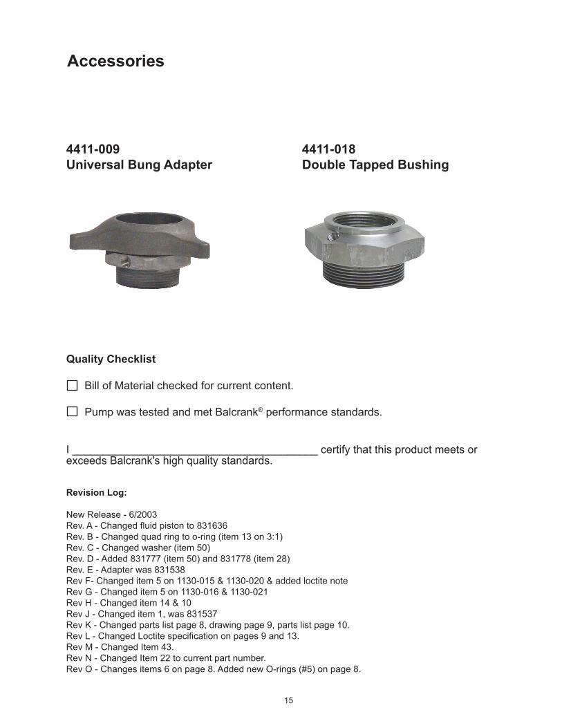
Accessories
4411-009 Universal Bung Adapter
4411-018Double Tapped Bushing
Quality Checklist
Bill of Material checked for current content.
Pump was tested and met Balcrank® performance standards.
I ________________________________________ certify that this product meets or exceeds Balcrank's high quality standards.
Revision Log:
New Release - 6/2003Rev. A - Changed fluid piston to 831636Rev. B - Changed quad ring to o-ring (item 13 on 3:1)Rev. C - Changed washer (item 50)Rev. D - Added 831777 (item 50) and 831778 (item 28)Rev. E - Adapter was 831538Rev F- Changed item 5 on 1130-015 & 1130-020 & added loctite noteRev G - Changed item 5 on 1130-016 & 1130-021Rev H - Changed item 14 & 10Rev J - Changed item 1, was 831537Rev K - Changed parts list page 8, drawing page 9, parts list page 10.Rev L - Changed Loctite specification on pages 9 and 13.Rev M - Changed Item 43.Rev N - Changed Item 22 to current part number.Rev O - Changes items 6 on page 8. Added new O-rings (#5) on page 8.

16
Balcrank® Products115 Reems Creek Rd.Weaverville, NC 28787800-747-5300800-763-0840 Faxwww.balcrank.com
Service Bulletin SB 1064Rev. O 02/09831601
Distributed by:
WARRANTyAll Balcrank® equipment sold by authorized Balcrank® distributors is warranted to their original customer to be free from defects in materials and workmanship for a period of one year from the date the equipment was sold to the original customer. Select equipment carries extended warranty terms as individually noted within the Balcrank®
Lubrication Equipment & Accessories User Price List. Any Balcrank® equipment carrying an extended warranty will be warranted for the period indicated; those items carrying a “lifetime” warranty are warranted for a period of thirty years. All Balcrank® equipment determined by Balcrank® to have defective materials or workmanship within the one year warranty period will be repaired or replaced. For equipment carrying extended warranties Balcrank®will repair or replace the product including parts and labor for the first full year and will provide parts only for the remaining period of the specified warranty.This warranty only covers equipment installed and operated according to applicable Balcrank® Service Bulletins and Installation Instructions. Any equipment claimed to be defective must be returned, freight prepaid, to an Authorized Balcrank® Service Center. If the part(s) or equipment is found to be defective, it will be repaired or replaced, and returned freight prepaid from the Authorized Service Center. If the claimed part(s) or equipment is found not to be defective, the Authorized Balcrank® Service Center will, upon written authorization being received from the original customer, repair them for a reasonable charge to the customer which will include all applicable parts, labor, and return transportation costs. Any equipment returned to Balcrank® must have the Warranty Service Claim number (WSC#) clearly marked on the outside of the carton. Balcrank’s sole responsibility is for defects in material and workmanship, and Buyer’s sole and exclusive remedy hereunder, shall be limited to repair or replacement of the defective part or equipment.This warranty does not cover, nor shall Balcrank® be liable for repair or replacement of parts or equipment resulting from general wear and tear through use, or damage or failure caused by improper installation, abuse, misapplication, abrasion, corrosion, insufficient or improper maintenance, negligence, accident, alteration, or substitution of non-Balcrank component parts. Furthermore the Balcrank® Warranty for Lubrication Equipment and Accessories does not cover the following specific conditions: Failure or damage to equipment that is caused by dirt or debris in air and fluid lines. This includes, but is not limited to clogged inlet filters, strainers, or regulators; fluid meters; control handles; fluid tips; and valves. Failure of normal wear parts including but not limited to: o-rings, packings, seals and valves unless originally improperly installed by the factory. Products placed in applications for which their use was not intended. Examples include but are not limited to: A lubricant pump being used to pump solvents, or placing a piece of equipment intended strictly for indoor use in an outdoor application. Damage to equipment resulting from operation above and beyond Balcrank’s recommendations. Leaks at air and fluid fittings and connections. Damage caused by thermal expansion when adequate pressure relief was not included in the system. Loose suction tubes on pumps. Reel spring tension adjustment.
THERE ARE NO OTHER WARRANTIES, EXPRESSED OR IMPLIED, INCLUDING WARRANTIES OF MER-CHANTABILITy OR FITNESS FOR A PARTICULAR PURPOSE. IN NO EVENT SHALL BALCRANK BE LIABLE FOR ANy SPECIAL, CONSEQUENTIAL, OR OTHER DAMAGES OF SIMILAR NATURE, INCLUDING BUT NOT LIMITED TO LOST PROFITS, LOST PRODUCTION, PROPERTy DAMAGE, PERSONAL INJURy, WHETHER SUFFERED By BUyER OR ANy THIRD PARTy, IRRESPECTIVE OF WHETHER CLAIMS OR ACTIONS, LEGAL OR EQUITABLE, FOR SUCH DAMAGES ARE BASED UPON CONTRACTS, WARRANTy, NEGLIGENCE, STRICT LIABILITy, OR OTHERWISE. ANy CLAIM OR ACTION FOR BREACH OF WARRANTy MUST BE BROUGHT WITHIN TWO (2) yEARS FROM THE DATE OF SALE TO THE ORIGINAL CUSTOMER.


![[XLS]tax.vermont.govtax.vermont.gov/sites/tax/files/documents/SPAN Data List... · Web view015-005-10947 015-005-10091 015-005-11649 015-005-10773 015-005-11222 015-005-10889 015-005-11109](https://static.fdocuments.us/doc/165x107/5ac161e67f8b9a5a4e8d129a/xlstax-data-listweb-view015-005-10947-015-005-10091-015-005-11649-015-005-10773.jpg)