Panoramic radiography OPG
142
Seminar no: 12 Dr Sanjana Ravindra Oral Medicine and Radiology Rajarajeswari Dental College and Hospital, Bangalore
-
Upload
drsanjana-ravindra -
Category
Health & Medicine
-
view
341 -
download
6
Transcript of Panoramic radiography OPG
Seminar no: 12
Dr Sanjana RavindraOral Medicine and RadiologyRajarajeswari Dental College
and Hospital, Bangalore
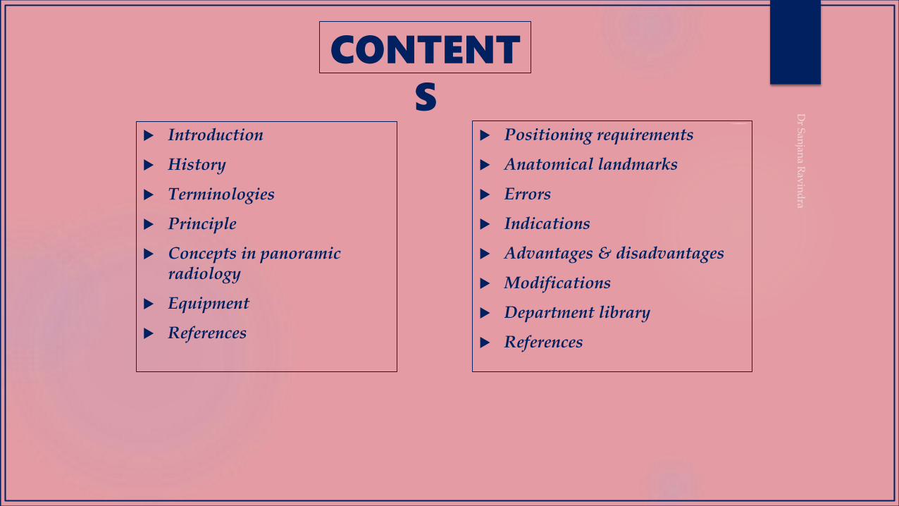
CONTENT
S Introduction
History
Terminologies
Principle
Concepts in panoramic radiology
Equipment
References
Positioning requirements
Anatomical landmarks
Errors
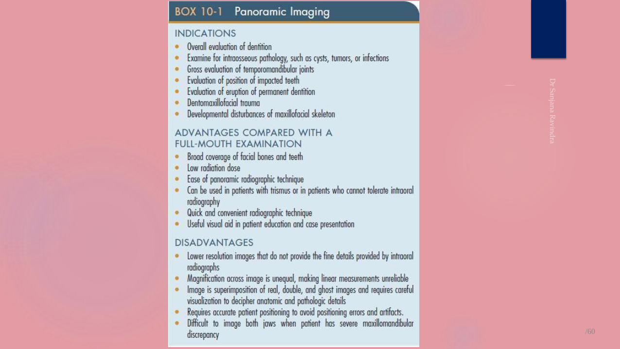
Indications
Advantages & disadvantages
Modifications
Department library
References

INTRODUCTION
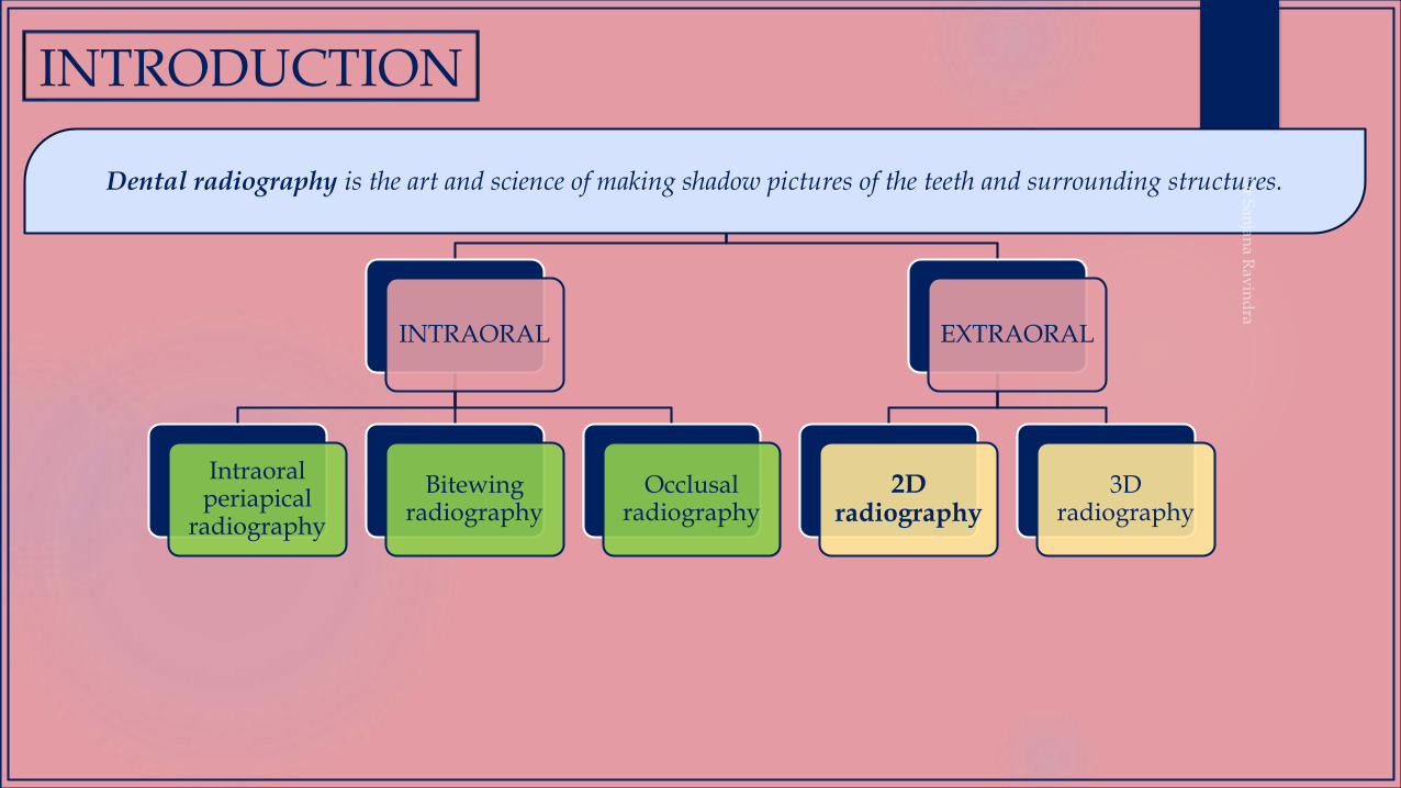
INTRODUCTION
INTRAORAL
Intraoral periapical
radiography
Bitewing radiography
Occlusal radiography
EXTRAORAL
2D radiography
3D radiography
Dental radiography is the art and science of making shadow pictures of the teeth and surrounding structures.
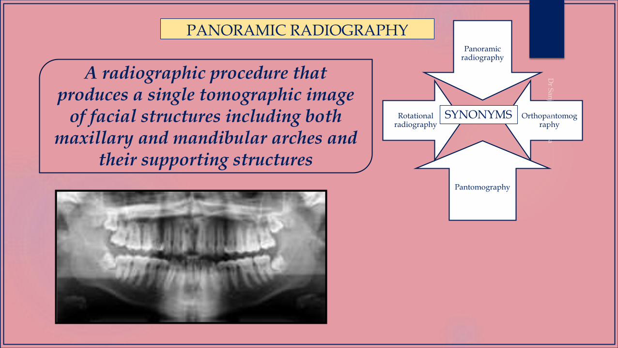
PANORAMIC RADIOGRAPHYPanoramic
radiography
Orthopantomography
Pantomography
Rotational radiography
SYNONYMS
A radiographic procedure that produces a single tomographic image
of facial structures including both maxillary and mandibular arches and
their supporting structures
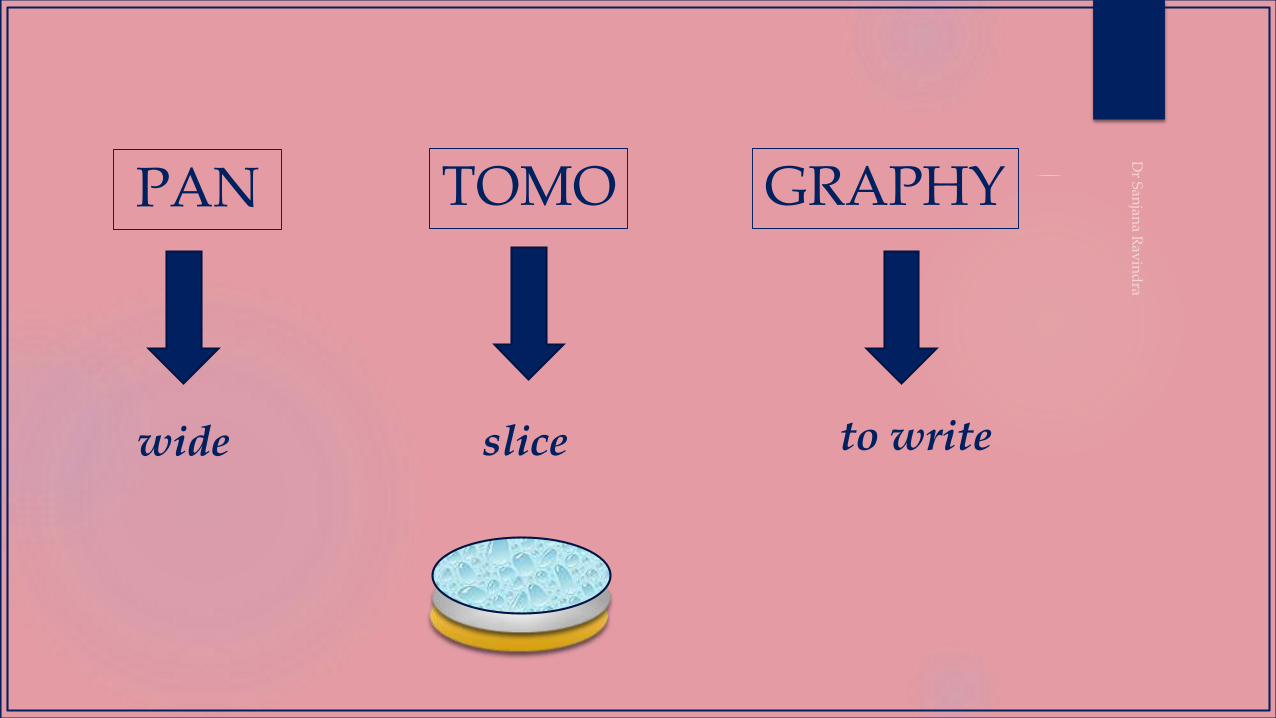
PAN TOMO GRAPHY
wide to writeslice

HISTORY
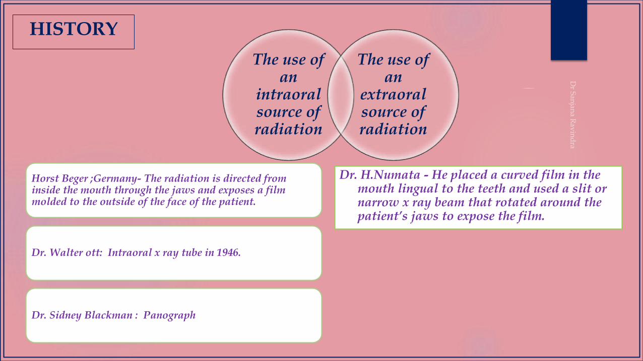
The use of an
intraoral source of radiation
The use of an
extraoral source of radiation
Horst Beger ;Germany- The radiation is directed from inside the mouth through the jaws and exposes a film molded to the outside of the face of the patient.
Dr. Walter ott: Intraoral x ray tube in 1946.
Dr. Sidney Blackman : Panograph
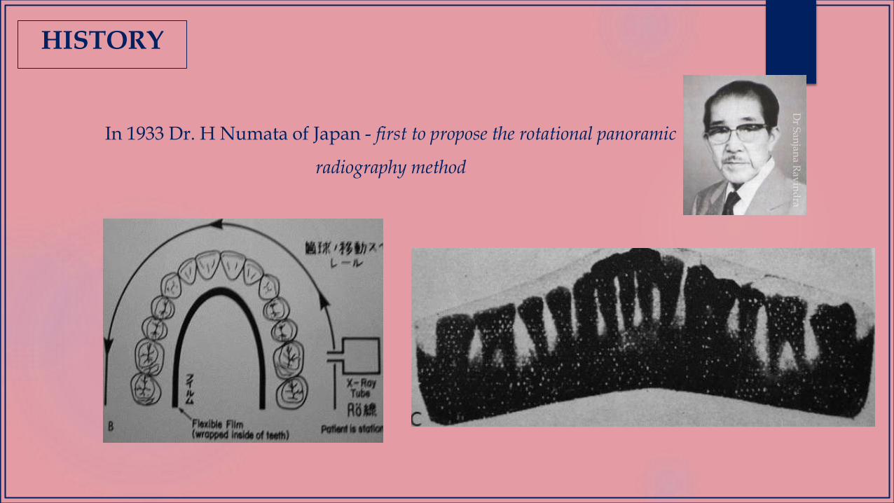
Dr. H.Numata - He placed a curved film in the mouth lingual to the teeth and used a slit or narrow x ray beam that rotated around the patient’s jaws to expose the film.
HISTORY
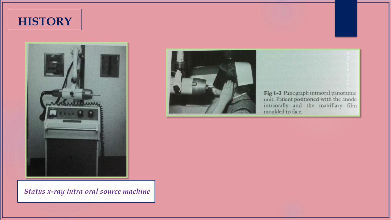
Status x-ray intra oral source machine
HISTORY
HISTORY
In 1933 Dr. H Numata of Japan - first to propose the rotational panoramic
radiography method
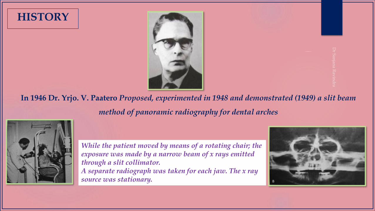
In 1946 Dr. Yrjo. V. Paatero Proposed, experimented in 1948 and demonstrated (1949) a slit beam
method of panoramic radiography for dental arches
HISTORY
While the patient moved by means of a rotating chair; the exposure was made by a narrow beam of x rays emitted through a slit collimator.A separate radiograph was taken for each jaw. The x ray source was stationary.
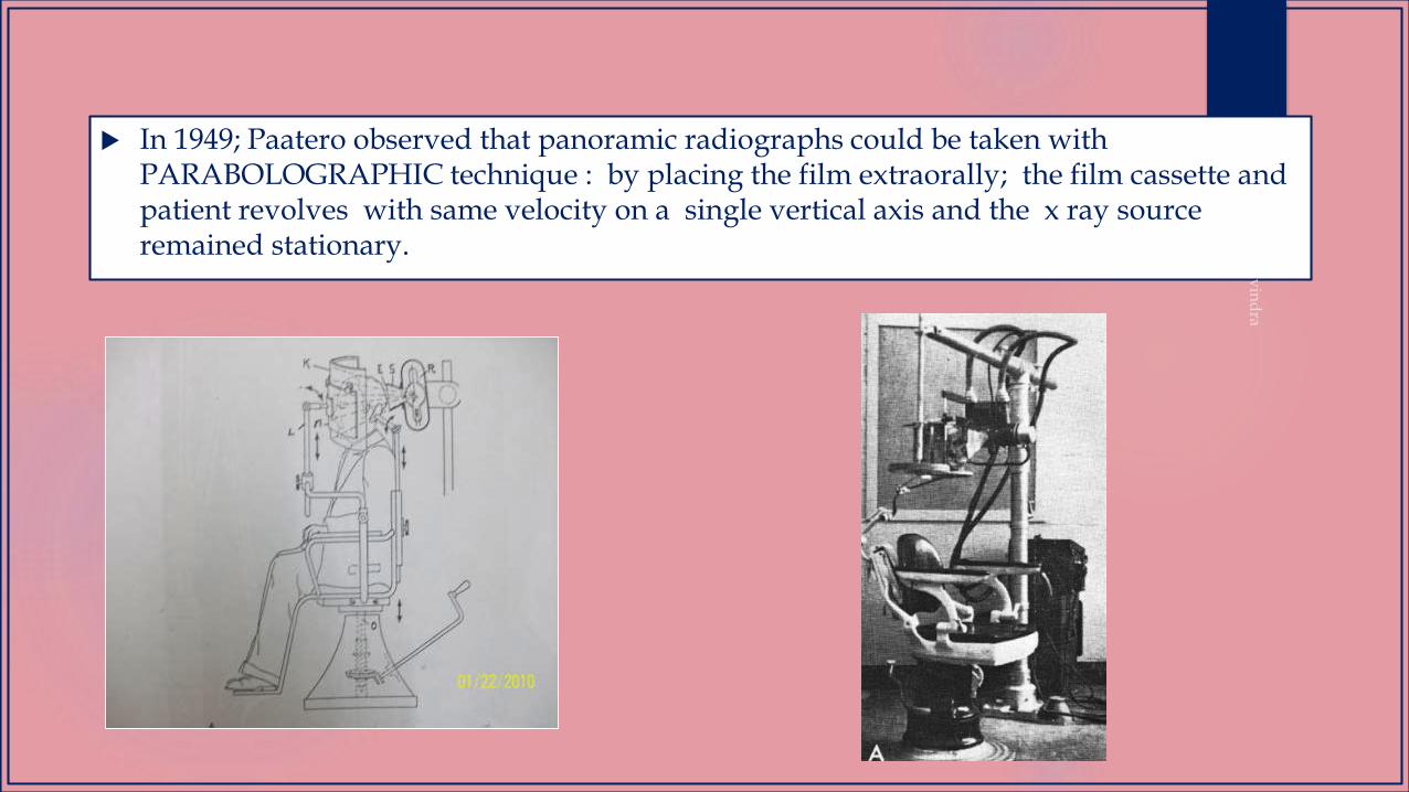
In 1949; Paatero observed that panoramic radiographs could be taken with PARABOLOGRAPHIC technique : by placing the film extraorally; the film cassette and patient revolves with same velocity on a single vertical axis and the x ray source remained stationary.
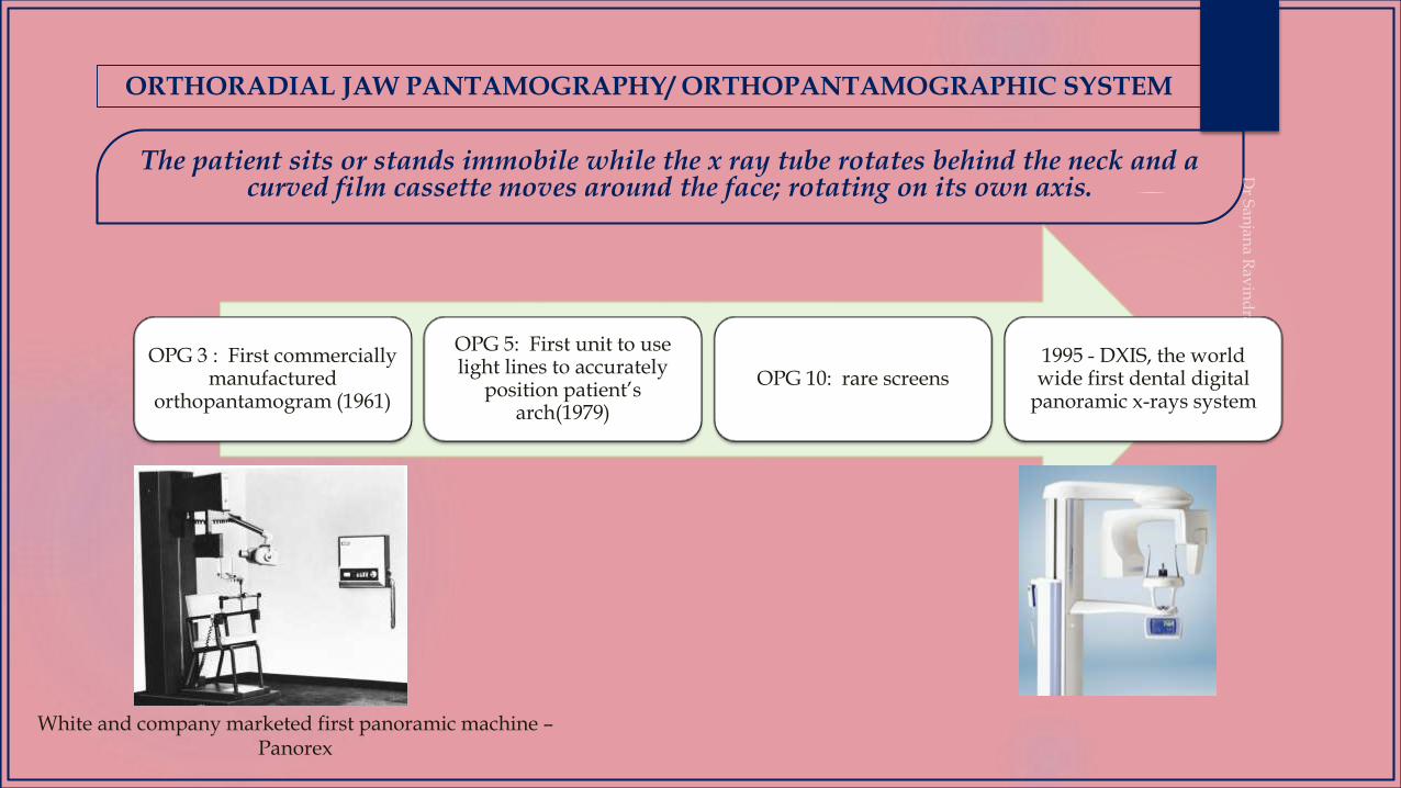
The patient sits or stands immobile while the x ray tube rotates behind the neck and a curved film cassette moves around the face; rotating on its own axis.
ORTHORADIAL JAW PANTAMOGRAPHY/ ORTHOPANTAMOGRAPHIC SYSTEM
OPG 3 : First commercially manufactured
orthopantamogram (1961)
OPG 5: First unit to use light lines to accurately
position patient’s arch(1979)
OPG 10: rare screens1995 - DXIS, the world wide first dental digital
panoramic x-rays system
White and company marketed first panoramic machine –Panorex

TERMINOLOGIES
AMPERE: the unit of intensity of an electric current produced by 1 volt(V) acting through a resistence of 1 ohm
ATTENUATION: the process by which a beam of radiation is reduced in energy when passing through matter
COLLIMATOR: beam- limiting device for restricting the field of x-ray photons in a beam to a desired shape and size
FOCAL SPOT: that part of the target of anx-ray tube that is bombarded by the focussed electron stream when the tube is energized
RADIATION ABSORBED DOSE(rad): a unit of measurement for the absorbed dose of any type of ionizing radiation in any medium
TARGET (x-ray tube): the part of the anode in an x-ray tube toward which electrons from the cathode are focussed and attracted and where they interact to produce x-radiation.

TOMOGRAPHY
TOMOGRAPHY
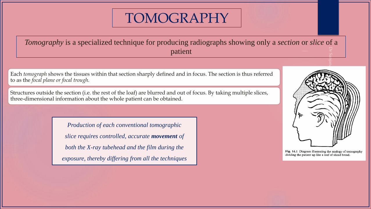
Tomography is a specialized technique for producing radiographs showing only a section or slice of a
patient
Each tomograph shows the tissues within that section sharply defined and in focus. The section is thus referred to as the focal plane or focal trough.
Structures outside the section (i.e. the rest of the loaf) are blurred and out of focus. By taking multiple slices, three-dimensional information about the whole patient can be obtained.
Production of each conventional tomographic
slice requires controlled, accurate movement of
both the X-ray tubehead and the film during the
exposure, thereby differing from all the techniques
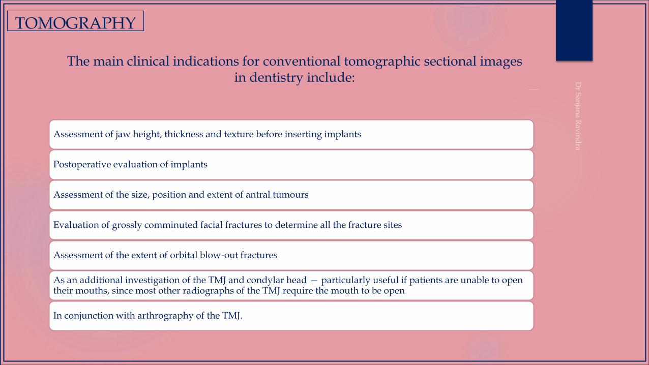
The main clinical indications for conventional tomographic sectional images in dentistry include:
Assessment of jaw height, thickness and texture before inserting implants
Postoperative evaluation of implants
Assessment of the size, position and extent of antral tumours
Evaluation of grossly comminuted facial fractures to determine all the fracture sites
Assessment of the extent of orbital blow-out fractures
As an additional investigation of the TMJ and condylar head — particularly useful if patients are unable to open their mouths, since most other radiographs of the TMJ require the mouth to be open
In conjunction with arthrography of the TMJ.
TOMOGRAPHY
TOMOGRAPHY
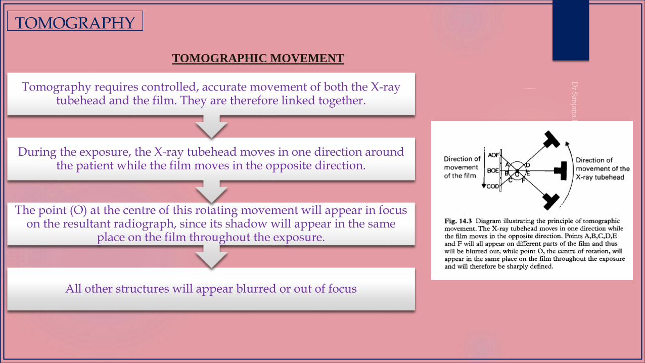
TOMOGRAPHIC MOVEMENT
All other structures will appear blurred or out of focus
The point (O) at the centre of this rotating movement will appear in focus on the resultant radiograph, since its shadow will appear in the same
place on the film throughout the exposure.
During the exposure, the X-ray tubehead moves in one direction around the patient while the film moves in the opposite direction.
Tomography requires controlled, accurate movement of both the X-ray tubehead and the film. They are therefore linked together.
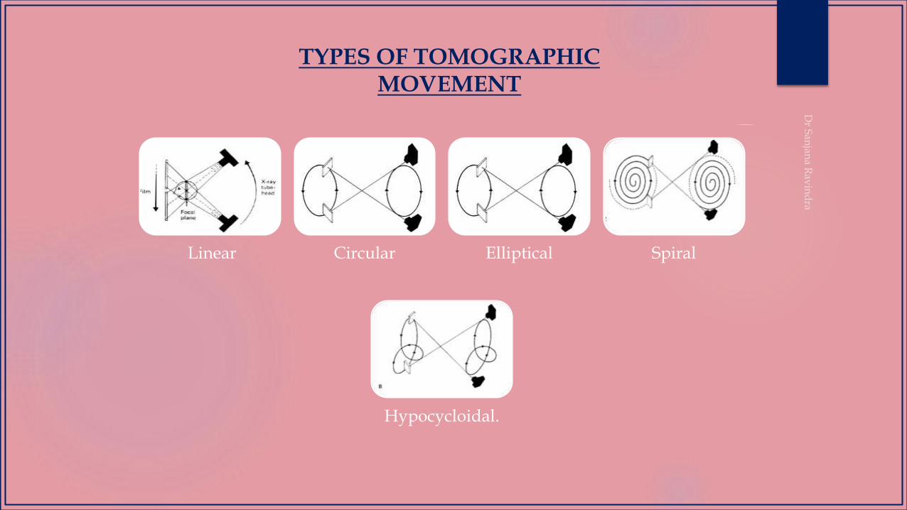
TYPES OF TOMOGRAPHIC MOVEMENT
Linear Circular Elliptical Spiral
Hypocycloidal.
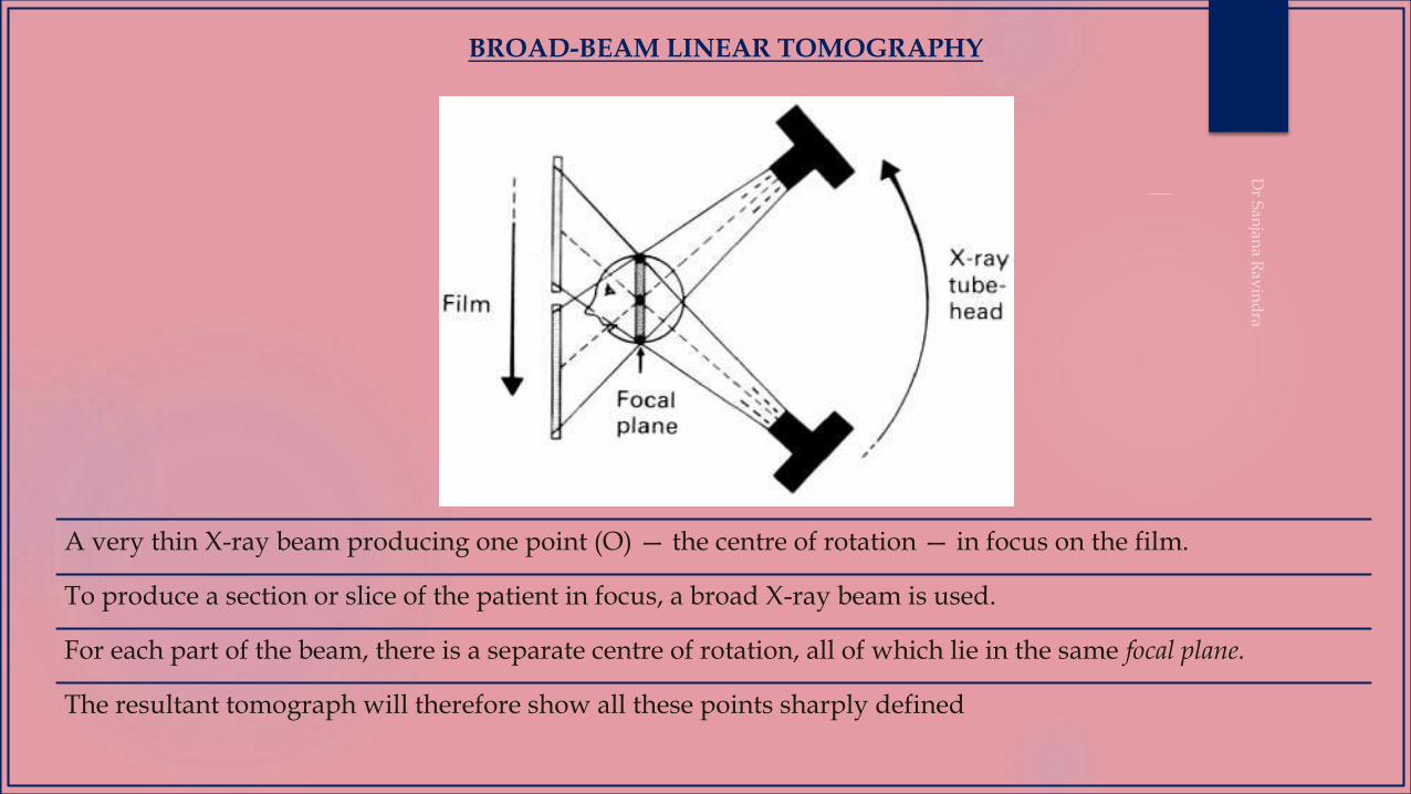
BROAD-BEAM LINEAR TOMOGRAPHY
A very thin X-ray beam producing one point (O) — the centre of rotation — in focus on the film.
To produce a section or slice of the patient in focus, a broad X-ray beam is used.
For each part of the beam, there is a separate centre of rotation, all of which lie in the same focal plane.
The resultant tomograph will therefore show all these points sharply defined
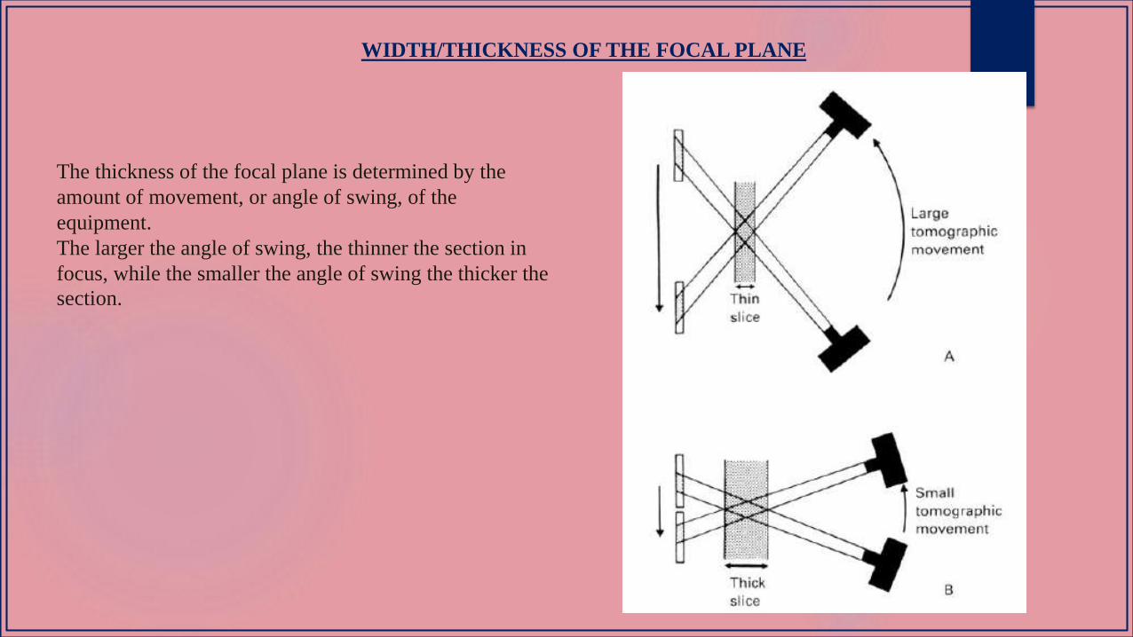
WIDTH/THICKNESS OF THE FOCAL PLANE
The thickness of the focal plane is determined by the
amount of movement, or angle of swing, of the
equipment.
The larger the angle of swing, the thinner the section in
focus, while the smaller the angle of swing the thicker the
section.

PRINCIPLE
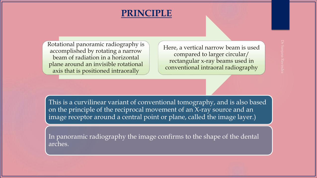
Rotational panoramic radiography is accomplished by rotating a narrow beam of radiation in a horizontal
plane around an invisible rotational axis that is positioned intraorally
Here, a vertical narrow beam is used compared to larger circular/
rectangular x-ray beams used in conventional intraoral radiography
This is a curvilinear variant of conventional tomography, and is also based on the principle of the reciprocal movement of an X-ray source and an image receptor around a central point or plane, called the image layer.)
In panoramic radiography the image confirms to the shape of the dental arches.
PRINCIPLE
PRINCIPLE
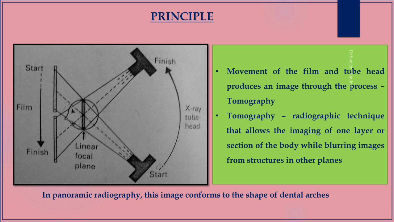
• Movement of the film and tube head
produces an image through the process –
Tomography
• Tomography – radiographic technique
that allows the imaging of one layer or
section of the body while blurring images
from structures in other planes
In panoramic radiography, this image conforms to the shape of dental arches
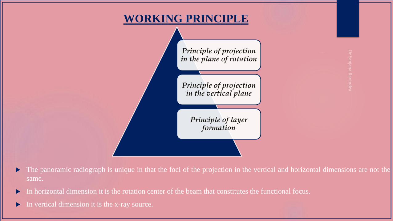
WORKING PRINCIPLE
Principle of projection in the plane of rotation
Principle of projection in the vertical plane
Principle of layer formation
The panoramic radiograph is unique in that the foci of the projection in the vertical and horizontal dimensions are not the
same.
In horizontal dimension it is the rotation center of the beam that constitutes the functional focus.
In vertical dimension it is the x-ray source.
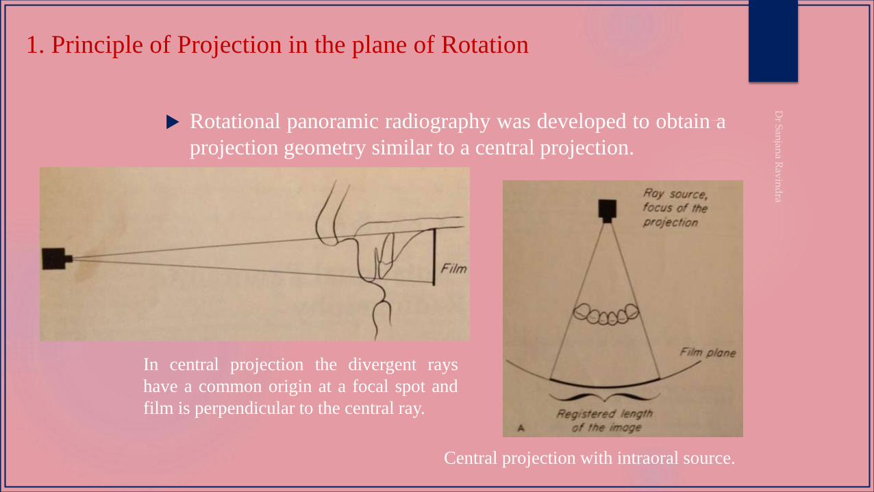
1. Principle of Projection in the plane of Rotation
Rotational panoramic radiography was developed to obtain a
projection geometry similar to a central projection.
In central projection the divergent rays
have a common origin at a focal spot and
film is perpendicular to the central ray.
Central projection with intraoral source.
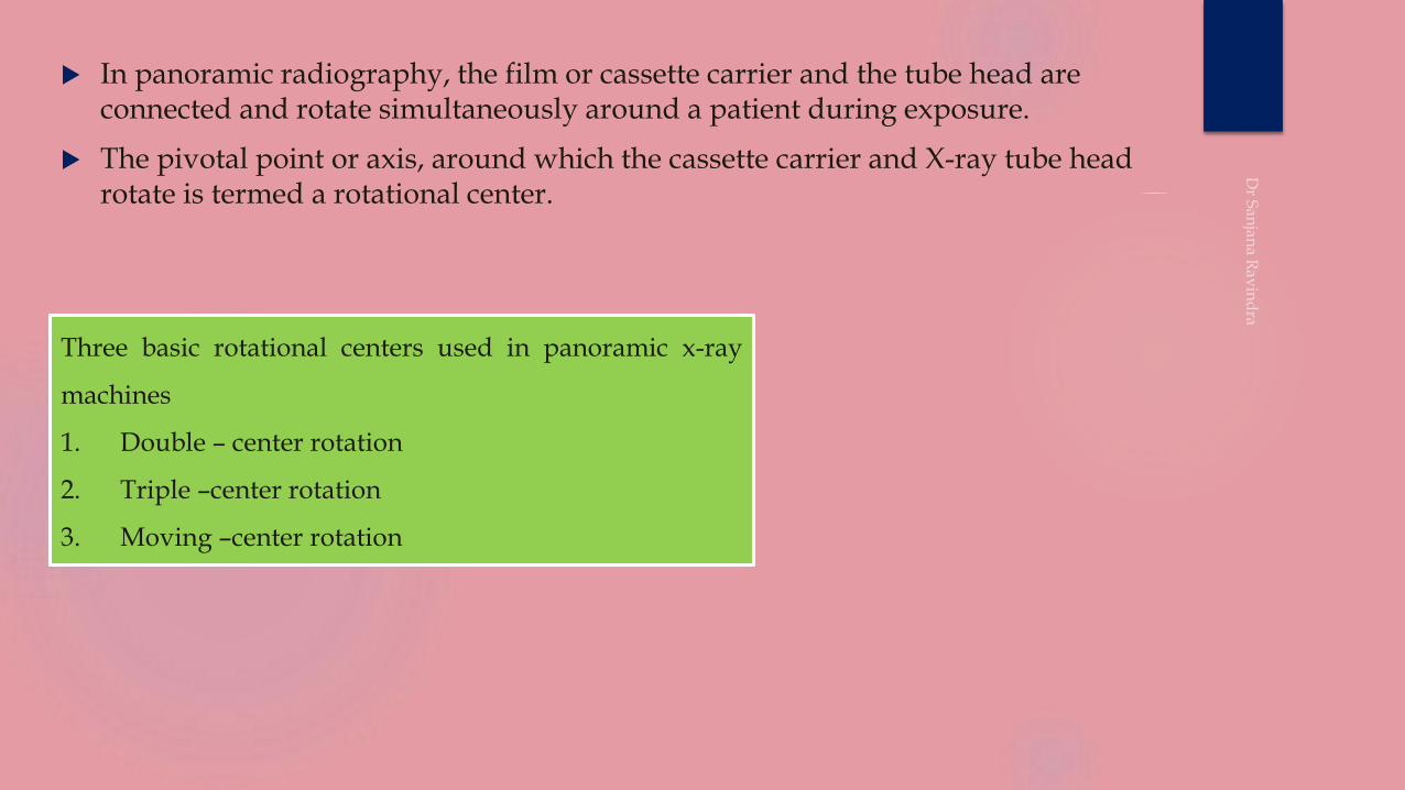
In panoramic radiography, the film or cassette carrier and the tube head are connected and rotate simultaneously around a patient during exposure.
The pivotal point or axis, around which the cassette carrier and X-ray tube head rotate is termed a rotational center.
Three basic rotational centers used in panoramic x-ray
machines
1. Double – center rotation
2. Triple –center rotation
3. Moving –center rotation
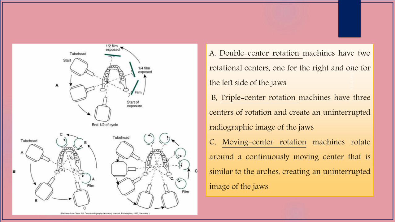
A, Double-center rotation machines have tworotational centers, one for the right and one forthe left side of the jawsB, Triple-center rotation machines have three
centers of rotation and create an uninterruptedradiographic image of the jawsC, Moving-center rotation machines rotatearound a continuously moving center that issimilar to the arches, creating an uninterruptedimage of the jaws
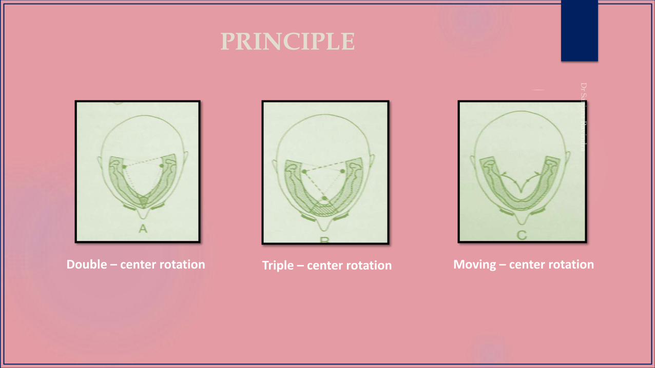
PRINCIPLE
Double – center rotation Triple – center rotation Moving – center rotation
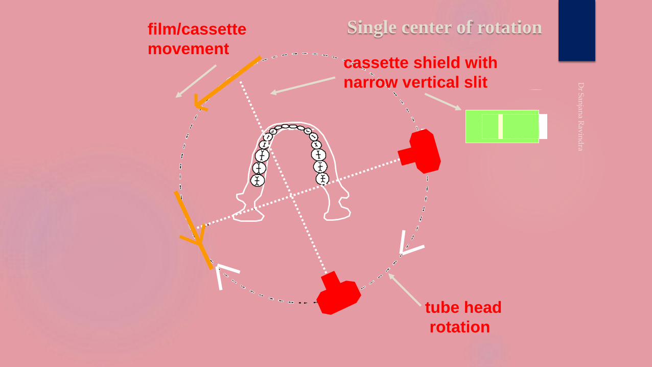
Single center of rotation
cassette shield with
narrow vertical slit
tube head
rotation
film/cassette
movement
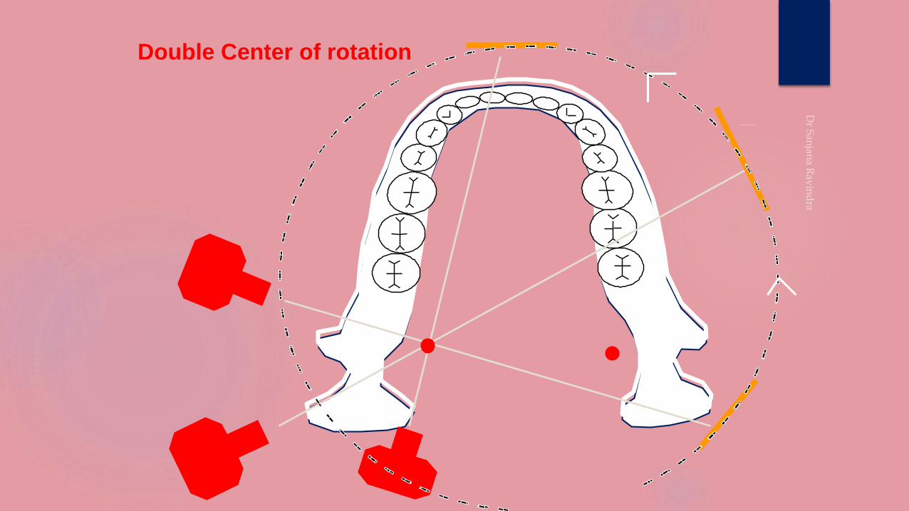
Double Center of rotation
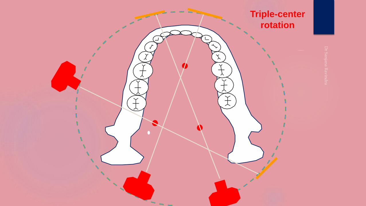
Triple-center
rotation
●
●
●
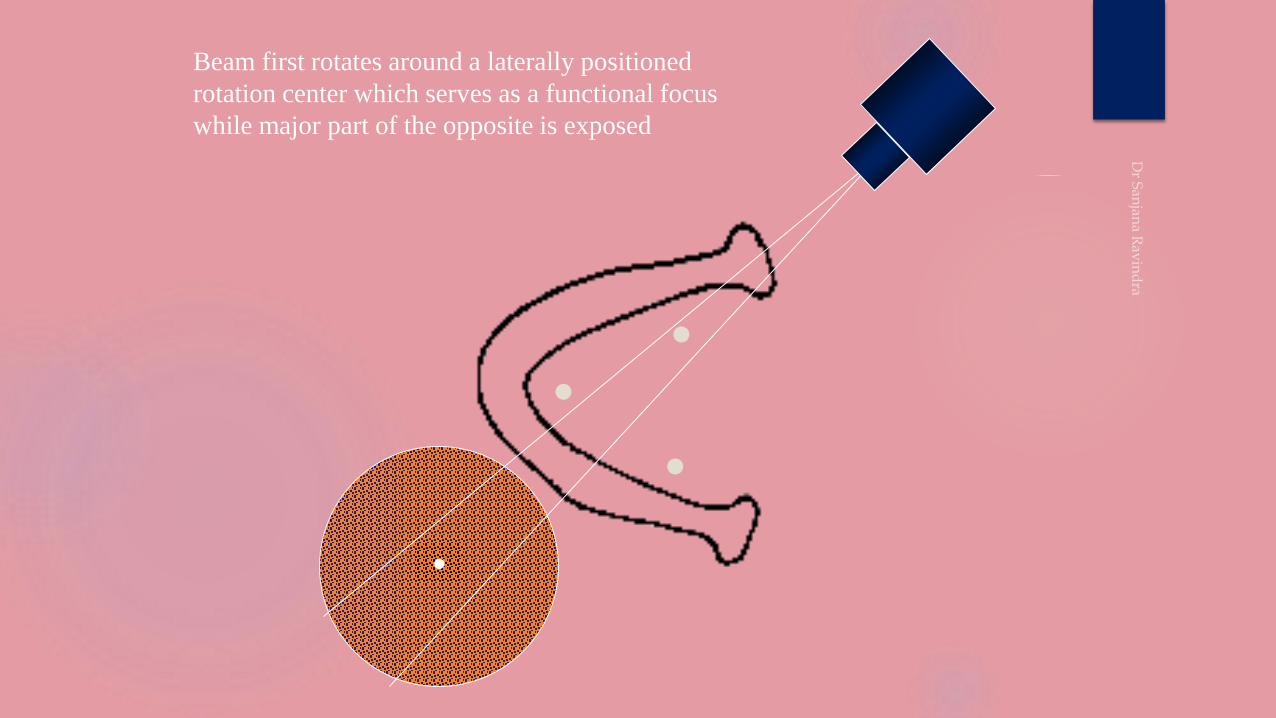
Beam first rotates around a laterally positioned
rotation center which serves as a functional focus
while major part of the opposite is exposed
●
●
●
●
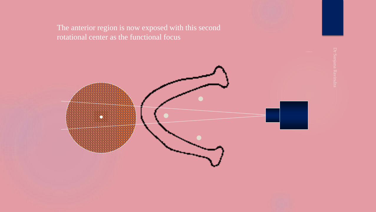
The anterior region is now exposed with this second
rotational center as the functional focus
●
●
●
●
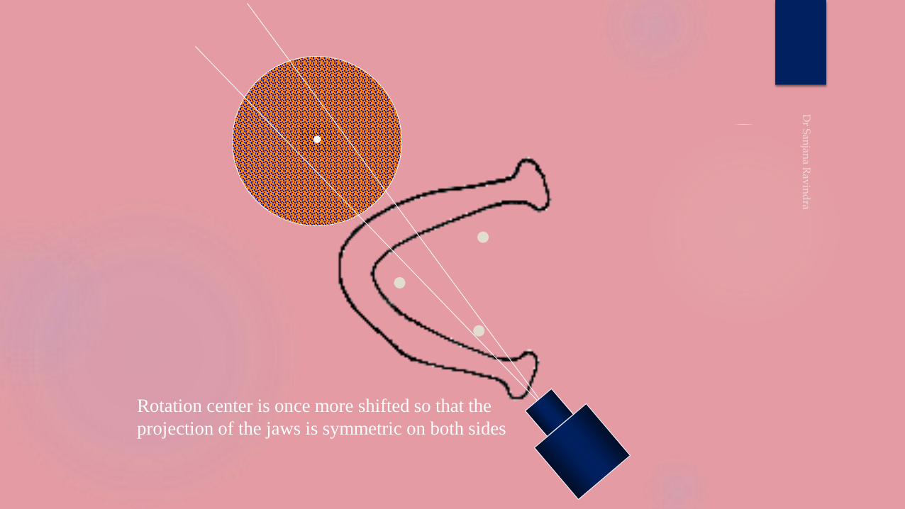
Rotation center is once more shifted so that the
projection of the jaws is symmetric on both sides
●
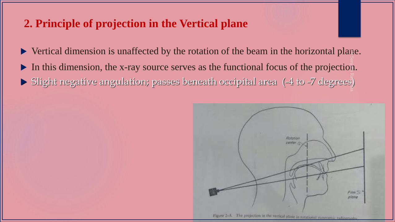
2. Principle of projection in the Vertical plane
Vertical dimension is unaffected by the rotation of the beam in the horizontal plane.
In this dimension, the x-ray source serves as the functional focus of the projection.
Slight negative angulation; passes beneath occipital area (-4 to -7 degrees)
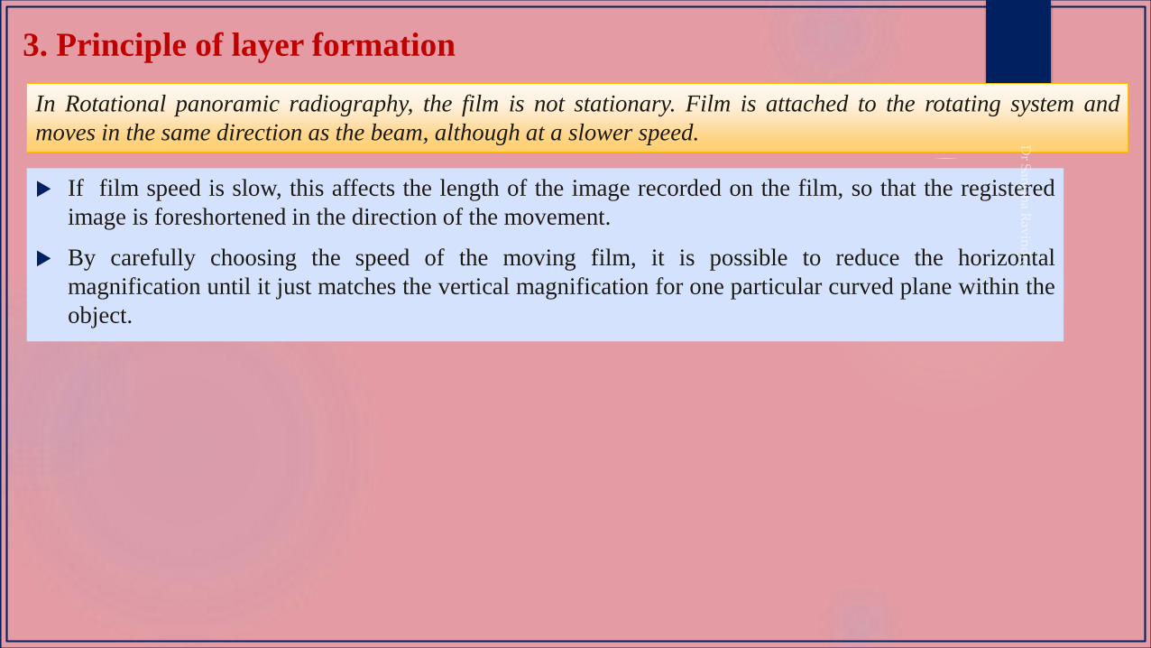
3. Principle of layer formation
In Rotational panoramic radiography, the film is not stationary. Film is attached to the rotating system and
moves in the same direction as the beam, although at a slower speed.
If film speed is slow, this affects the length of the image recorded on the film, so that the registered
image is foreshortened in the direction of the movement.
By carefully choosing the speed of the moving film, it is possible to reduce the horizontal
magnification until it just matches the vertical magnification for one particular curved plane within the
object.
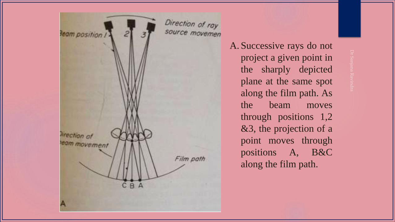
A. Successive rays do not
project a given point in
the sharply depicted
plane at the same spot
along the film path. As
the beam moves
through positions 1,2
&3, the projection of a
point moves through
positions A, B&C
along the film path.
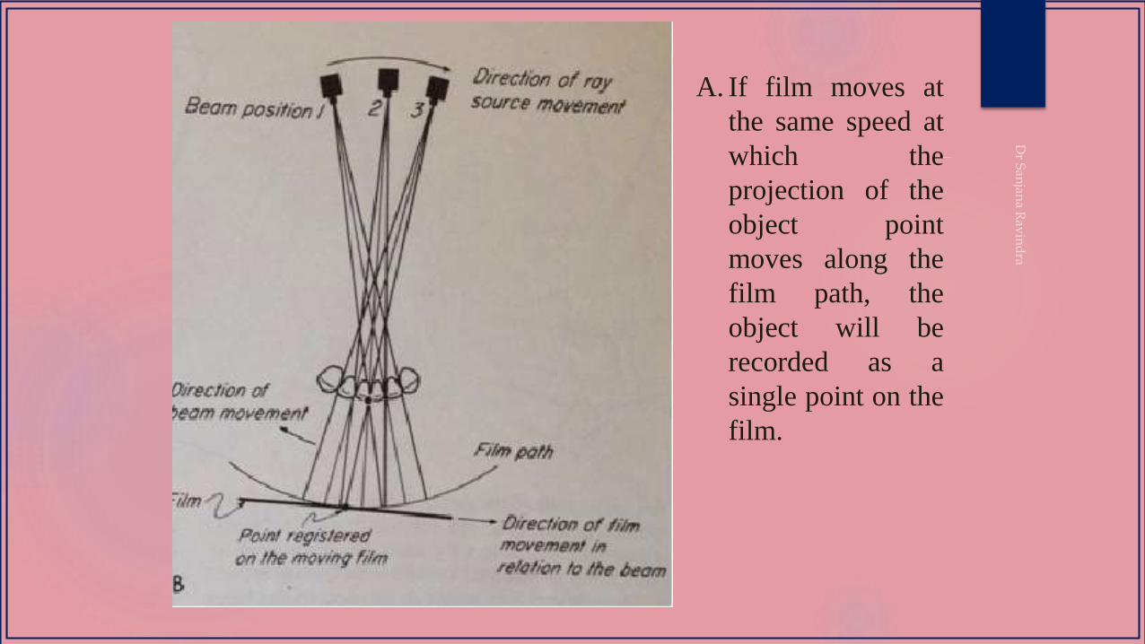
A. If film moves at
the same speed at
which the
projection of the
object point
moves along the
film path, the
object will be
recorded as a
single point on the
film.
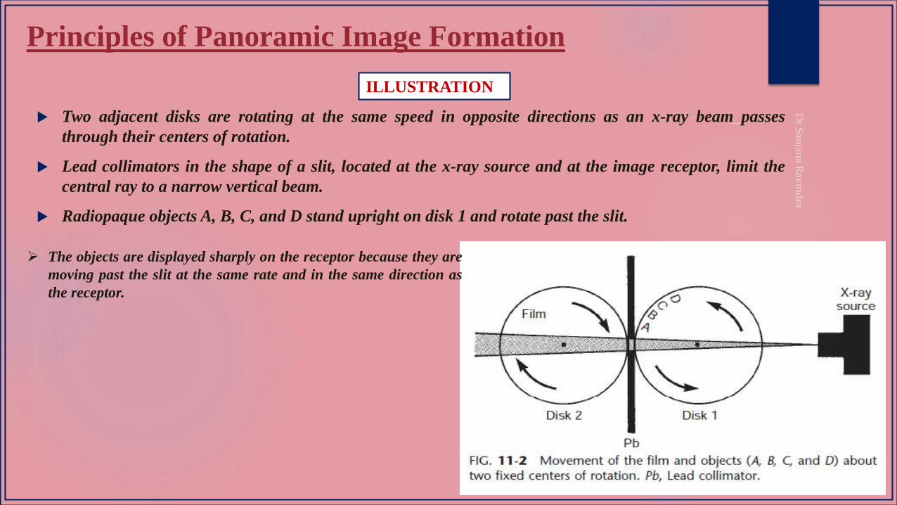
Principles of Panoramic Image Formation
Two adjacent disks are rotating at the same speed in opposite directions as an x-ray beam passes
through their centers of rotation.
Lead collimators in the shape of a slit, located at the x-ray source and at the image receptor, limit the
central ray to a narrow vertical beam.
Radiopaque objects A, B, C, and D stand upright on disk 1 and rotate past the slit.
ILLUSTRATION
The objects are displayed sharply on the receptor because they are
moving past the slit at the same rate and in the same direction as
the receptor.
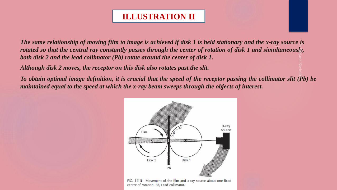
ILLUSTRATION II
The same relationship of moving film to image is achieved if disk 1 is held stationary and the x-ray source is
rotated so that the central ray constantly passes through the center of rotation of disk 1 and simultaneously,
both disk 2 and the lead collimator (Pb) rotate around the center of disk 1.
Although disk 2 moves, the receptor on this disk also rotates past the slit.
To obtain optimal image definition, it is crucial that the speed of the receptor passing the collimator slit (Pb) be
maintained equal to the speed at which the x-ray beam sweeps through the objects of interest.

As the tubehead rotates around the patient, the x-ray
beam passes through different parts of the jaws,
producing multiple images that appear as one
continuous image on the film (“panoramic view”). When
you click the mouse, the tubehead will rotate around the
patient and produce the images. The red dots represent
the sliding rotation center.
The film above shows the left side of the patient
on the left. We normally look at the film as if we
were facing the patient, so that the patient’s
right side is on our left. Click the mouse to
rotate the film into the correct orientation for
viewing .
In panoramic radiography, the film or cassette carrier and the tube
head are connected and rotate simultaneously around a patient
during exposure. The pivotal point or axis around which the cassette
carrier and the X-ray tube head rotate is termed as rotation center.
The Rotation center concept has advanced from Stationary to
Continuously moving to combined stationary and moving rotation
centers.
ROTATION CENTER
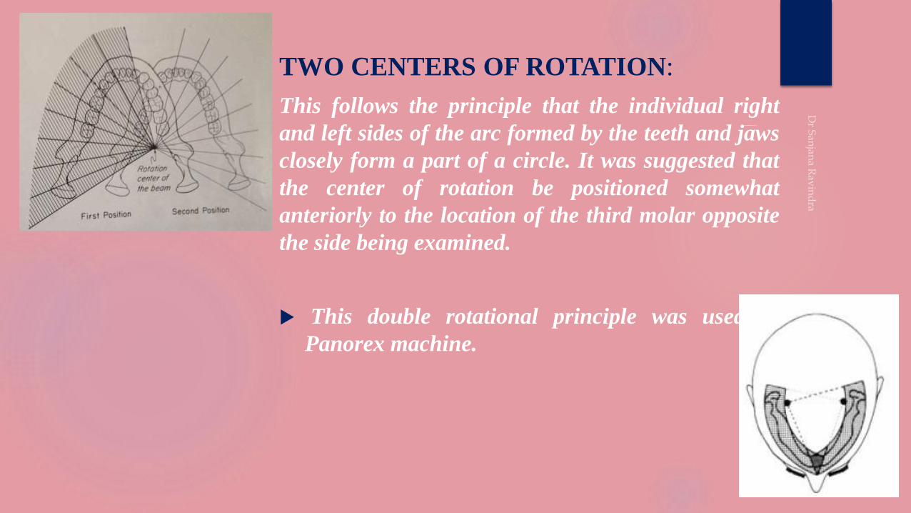
TWO CENTERS OF ROTATION:
This follows the principle that the individual right
and left sides of the arc formed by the teeth and jaws
closely form a part of a circle. It was suggested that
the center of rotation be positioned somewhat
anteriorly to the location of the third molar opposite
the side being examined.
This double rotational principle was used in
Panorex machine.
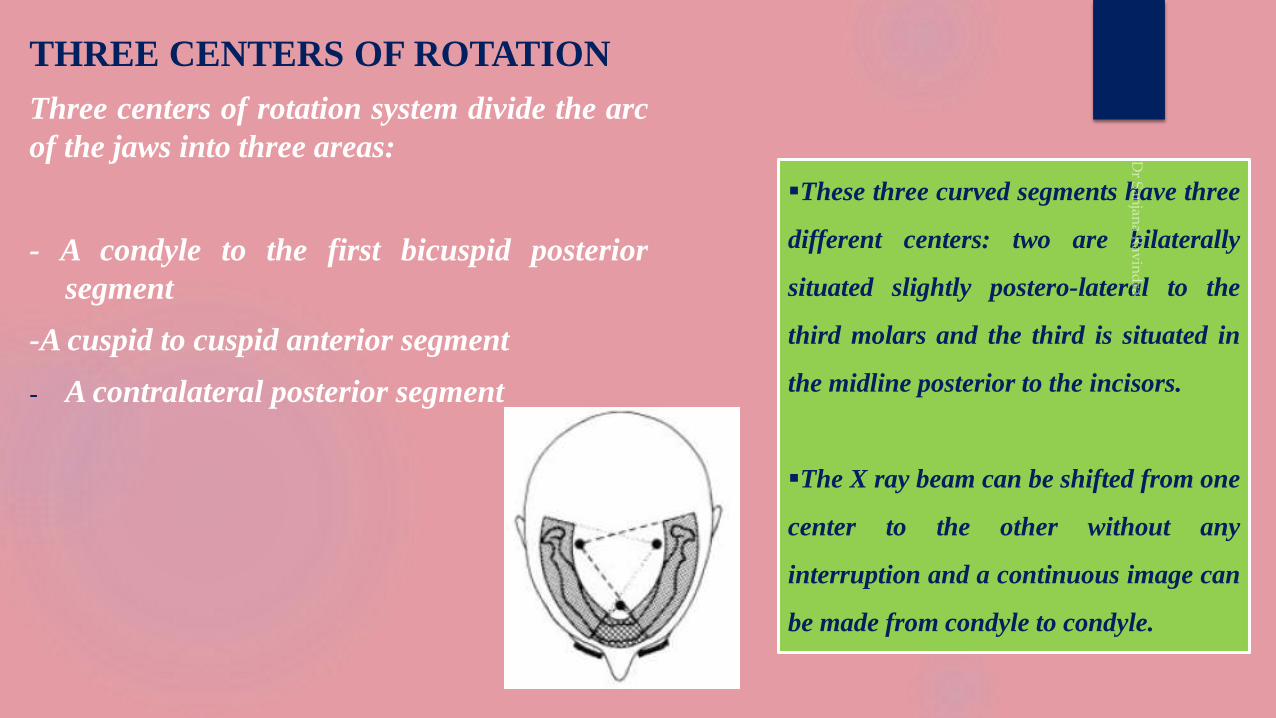
THREE CENTERS OF ROTATION
Three centers of rotation system divide the arc
of the jaws into three areas:
- A condyle to the first bicuspid posterior
segment
-A cuspid to cuspid anterior segment
- A contralateral posterior segment
These three curved segments have three
different centers: two are bilaterally
situated slightly postero-lateral to the
third molars and the third is situated in
the midline posterior to the incisors.
The X ray beam can be shifted from one
center to the other without any
interruption and a continuous image can
be made from condyle to condyle.
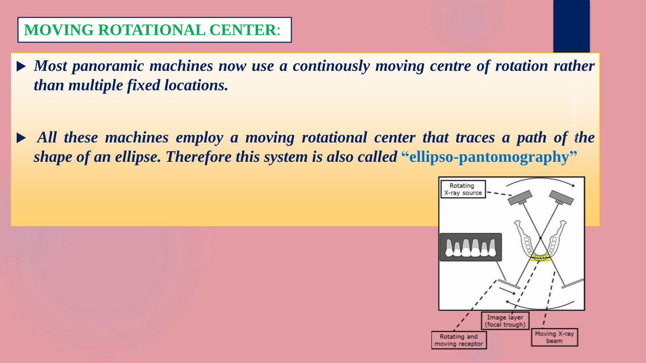
Most panoramic machines now use a continously moving centre of rotation rather
than multiple fixed locations.
All these machines employ a moving rotational center that traces a path of the
shape of an ellipse. Therefore this system is also called “ellipso-pantomography”
MOVING ROTATIONAL CENTER:
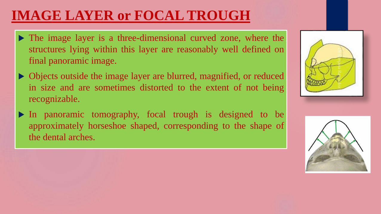
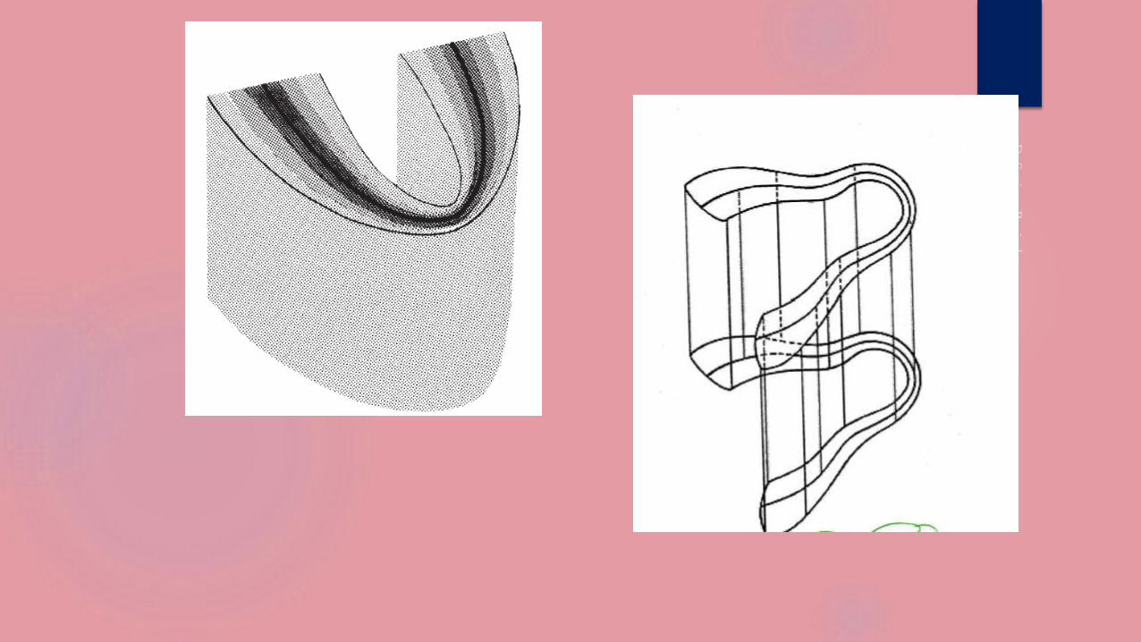
IMAGE LAYER or FOCAL TROUGH
The image layer is a three-dimensional curved zone, where the
structures lying within this layer are reasonably well defined on
final panoramic image.
Objects outside the image layer are blurred, magnified, or reduced
in size and are sometimes distorted to the extent of not being
recognizable.
In panoramic tomography, focal trough is designed to be
approximately horseshoe shaped, corresponding to the shape of
the dental arches.
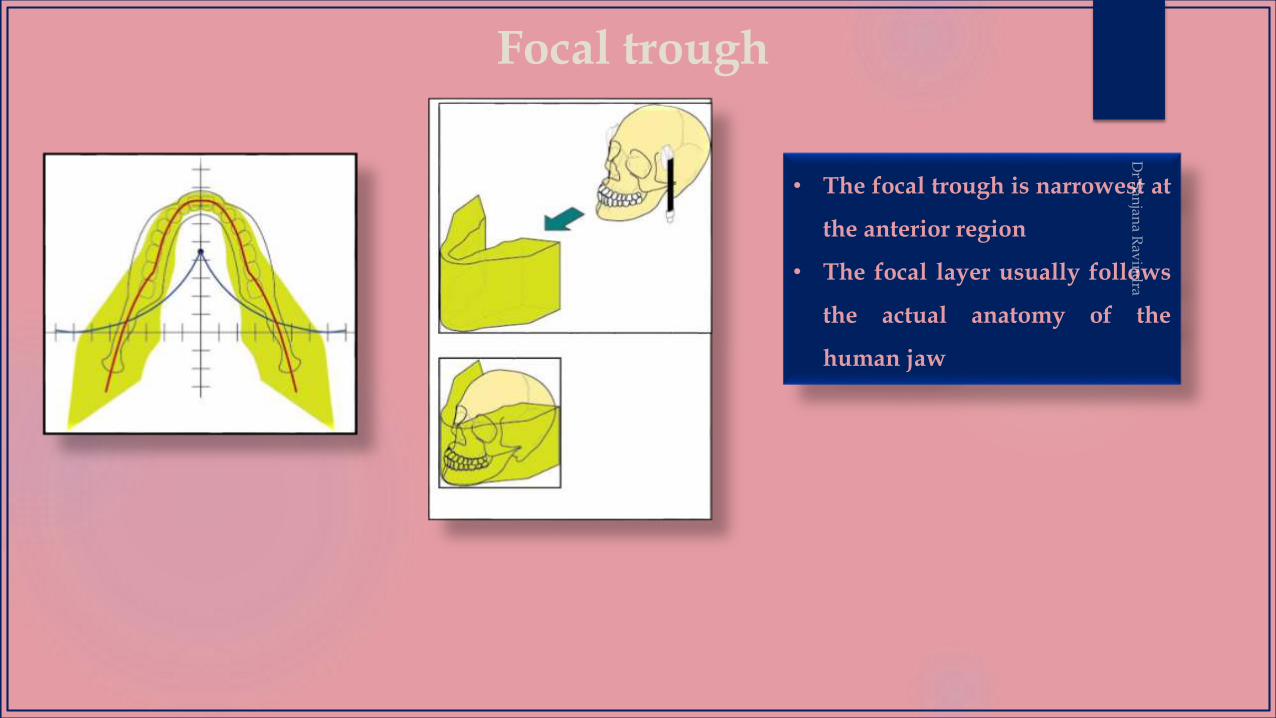
Focal trough
• The focal trough is narrowest at
the anterior region
• The focal layer usually follows
the actual anatomy of the
human jaw
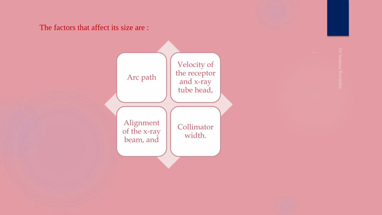
Arc path
Velocity of the receptor
and x-ray tube head,
Alignment of the x-ray beam, and
Collimator width.
The factors that affect its size are :
Distance from rotation center of the beam to the central plane
of the image layer has been called the effective projection
radius.
The thickness of the layer depends on the length of this radius;
the longer this radius, the thicker the layer.
Thus altered film speed relative to beam changes the position
and thickness of the layer.
A constant film speed in relation to the
beam places the central plane of the
image layer at a defined distance from
the rotation center of the beam.
If the speed of the film is increased,
the position of the layer shifts away
from the rotation center.
If the speed of the film is decreased,
the position of the layer shifts towards
the rotation center.

EQUIPMENT
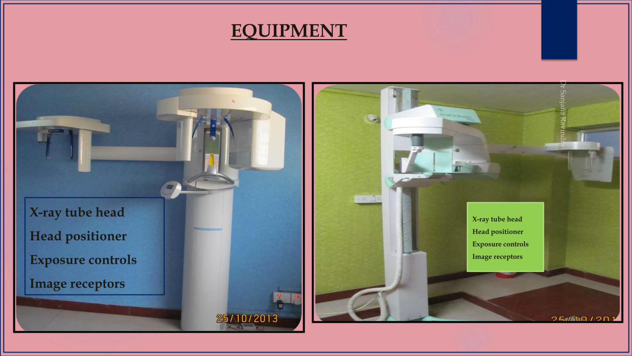
EQUIPMENT
X-ray tube head
Head positioner
Exposure controls
Image receptors
X-ray tube head
Head positioner
Exposure controls
Image receptors
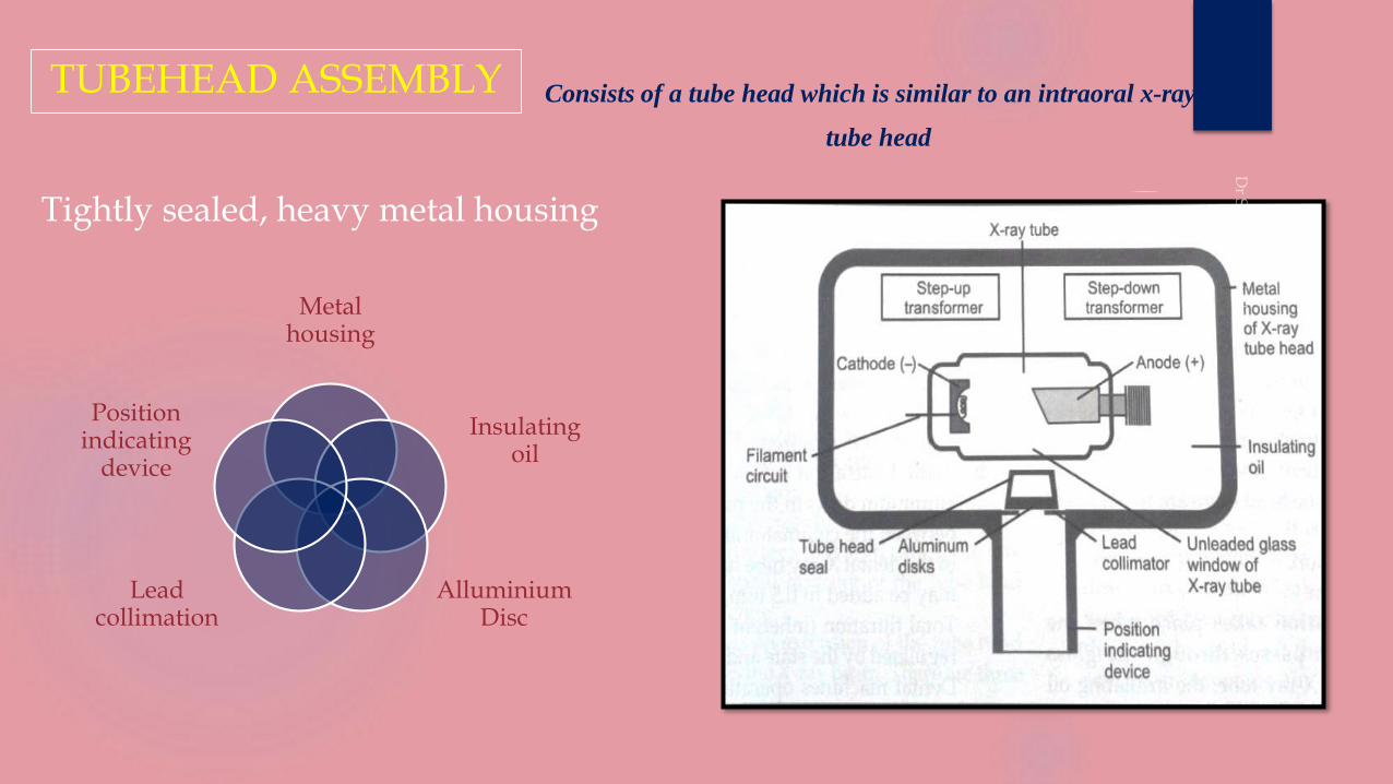
TUBEHEAD ASSEMBLY
Tightly sealed, heavy metal housing
Metal housing
Insulating oil
Alluminium Disc
Lead collimation
Position indicating
device
Consists of a tube head which is similar to an intraoral x-ray
tube head
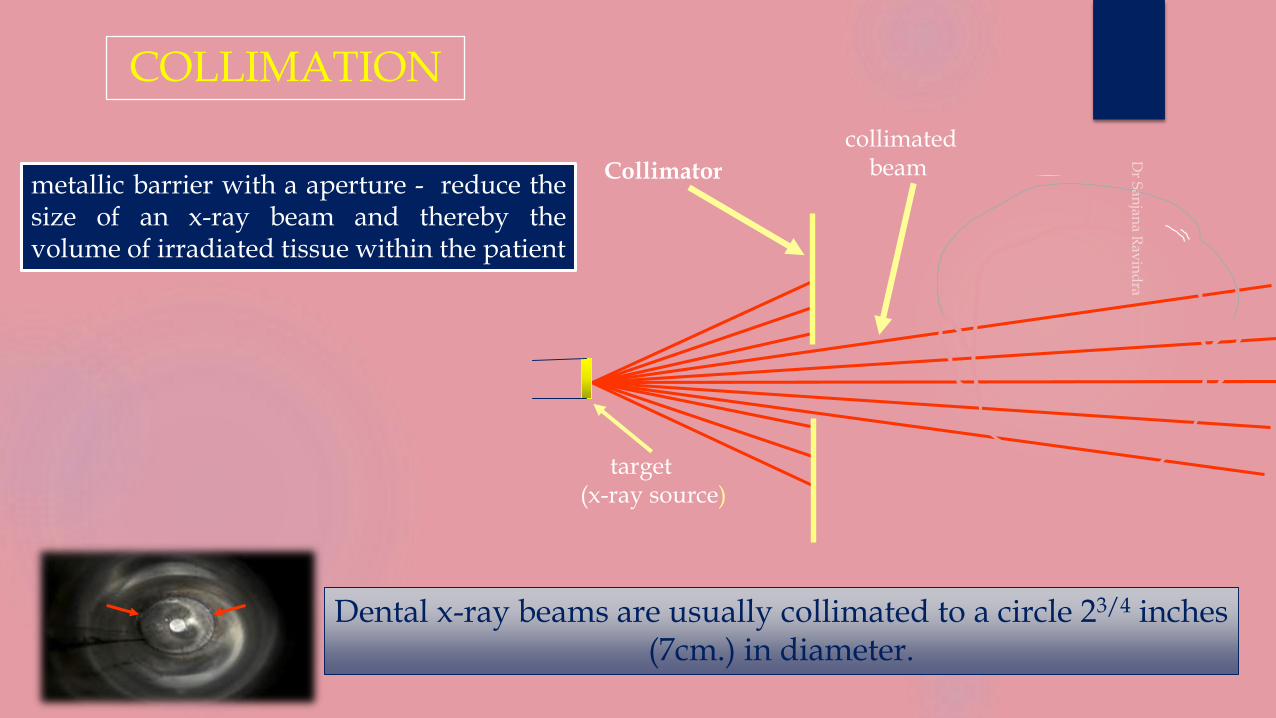
collimated beamCollimator
target(x-ray source)
COLLIMATION
Dental x-ray beams are usually collimated to a circle 23/4 inches (7cm.) in diameter.
metallic barrier with a aperture - reduce thesize of an x-ray beam and thereby thevolume of irradiated tissue within the patient
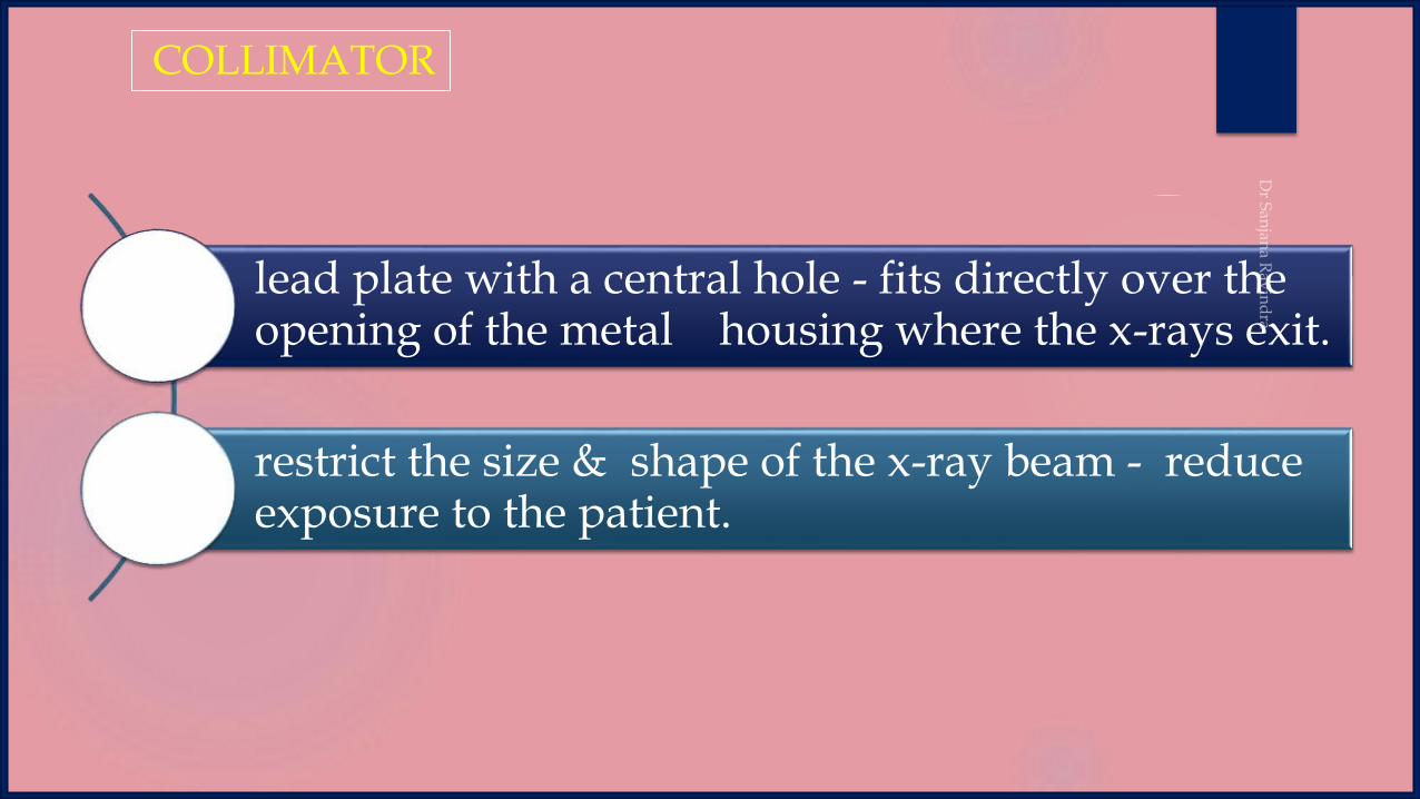
lead plate with a central hole - fits directly over the opening of the metal housing where the x-rays exit.
restrict the size & shape of the x-ray beam - reduce exposure to the patient.
COLLIMATOR
intraoral
collimation
panoramic
collimation
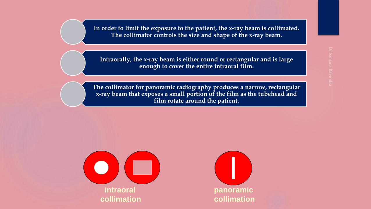
In order to limit the exposure to the patient, the x-ray beam is collimated. The collimator controls the size and shape of the x-ray beam.
Intraorally, the x-ray beam is either round or rectangular and is large enough to cover the entire intraoral film.
The collimator for panoramic radiography produces a narrow, rectangular x-ray beam that exposes a small portion of the film as the tubehead and
film rotate around the patient.
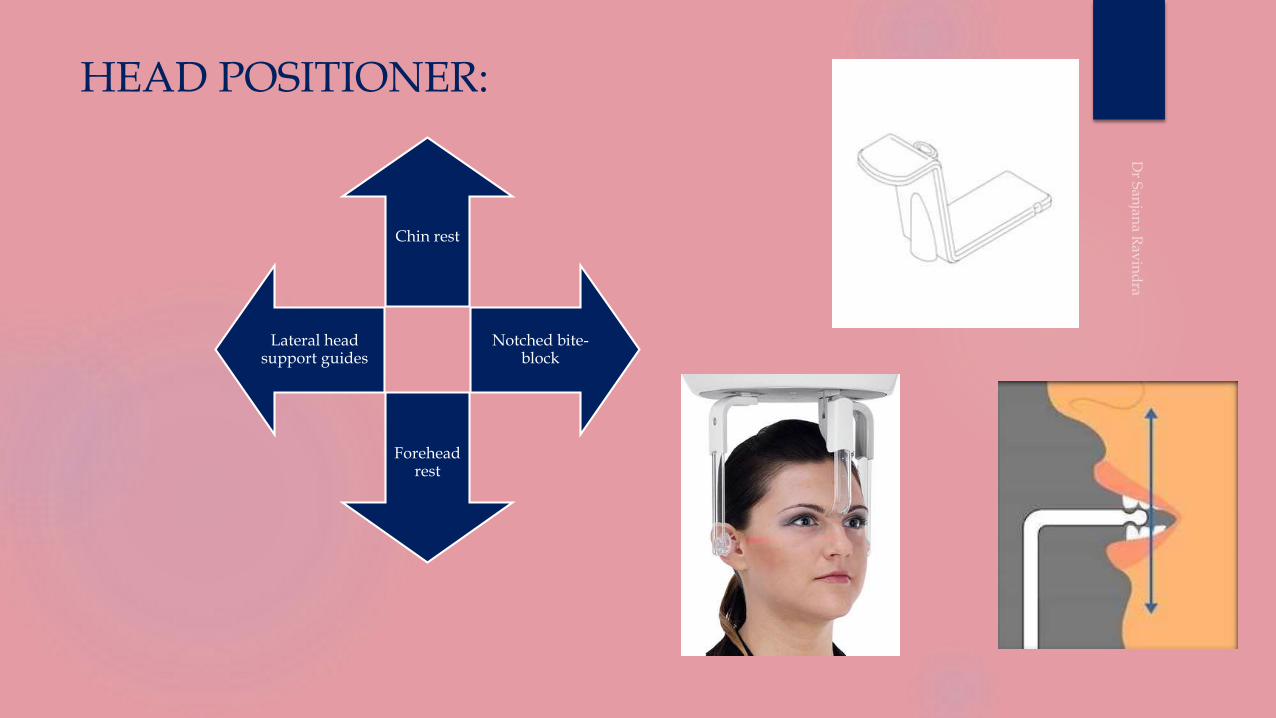
HEAD POSITIONER:
Chin rest
Notched bite-block
Forehead rest
Lateral head support guides

EXPOSURE PARAMETERS
• Kvp - 72 ; mA - 8 ; Exposure time 18 sec
Dose to the patient - 0.103mR
• Kvp - 80 ; mA 15 ; Exposure time 15 sec
Dose to the patient - 0.116mR
• In case of full mouth examination with 14 intraoral films
Dose to the patient 0.712mR
Exposure factors are determined by the manufacturer who suggests the
(Kvp and Milliamperage).
The Kvp and milliamperage settings are adjustable and can be varied to
accommodate patients of different sizes
The Exposure time is fixed and can‟t be changed
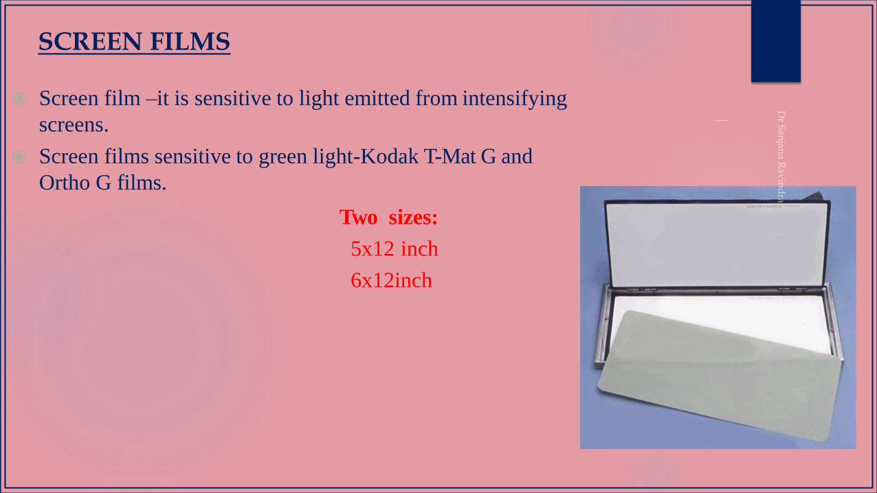
Screen film –it is sensitive to light emitted from intensifying
screens.
Screen films sensitive to green light-Kodak T-Mat G and
Ortho G films.
Two sizes:
5x12 inch
6x12inch
SCREEN FILMS

INTENSIFYING SCREENS
Phosphors are materials which convert photon energy to light.
Intensifying screens make use of the principle of fluorescence (emission of visible light).
Certain inorganic salts or phosphors (e.g. Magnesium Oxide or Titanium Dioxide or Calcium Tungstate) have the property of absorbing X-ray photons and emitting visible light.
An intensifying screen is a plastic sheet coated with fluorescent material called phosphors
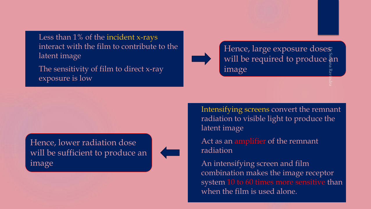
Less than 1% of the incident x-rays interact with the film to contribute to the latent image
The sensitivity of film to direct x-ray exposure is low
Intensifying screens convert the remnant radiation to visible light to produce the latent image
Act as an amplifier of the remnant radiation
An intensifying screen and film combination makes the image receptor system 10 to 60 times more sensitive than when the film is used alone.
Hence, large exposure doses will be required to produce an image
Hence, lower radiation dose will be sufficient to produce an image
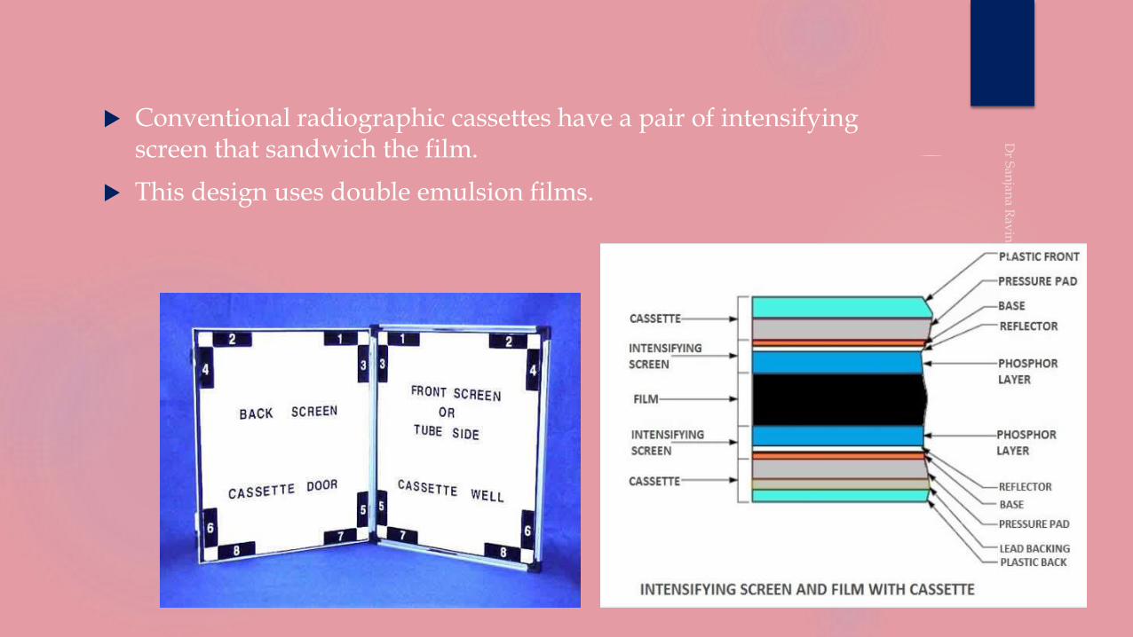
Conventional radiographic cassettes have a pair of intensifying screen that sandwich the film.
This design uses double emulsion films.
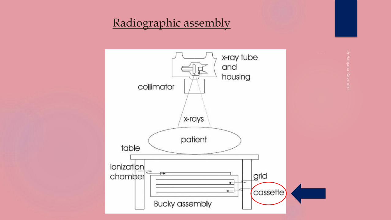
Radiographic assembly
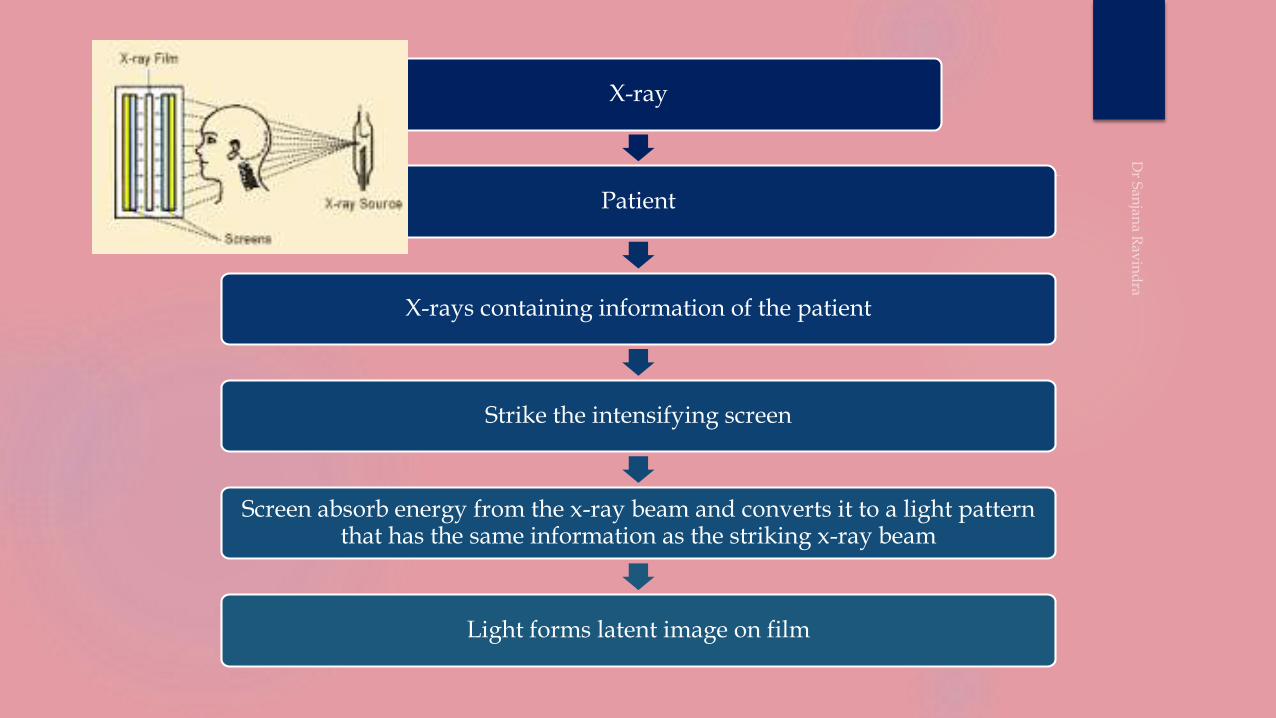
X-ray
Patient
X-rays containing information of the patient
Strike the intensifying screen
Screen absorb energy from the x-ray beam and converts it to a light pattern that has the same information as the striking x-ray beam
Light forms latent image on film
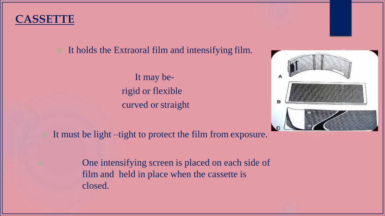
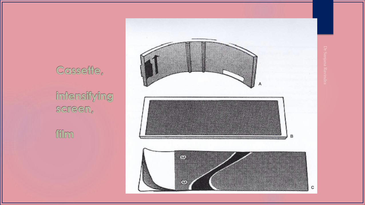
It holds the Extraoral film and intensifying film.
It may be-
rigid or flexible
curved or straight
It must be light –tight to protect the film from exposure.
One intensifying screen is placed on each side of
film and held in place when the cassette is
closed.
CASSETTE
These transmits an electric signal to the controlling computer,which displays the image on
computer screen.
Both the digital modalities allow the user to perform post processing modifications on the
image including linear contrast and density adjustments, black/white reversal,
magnification, edge enhancement and color rendering.
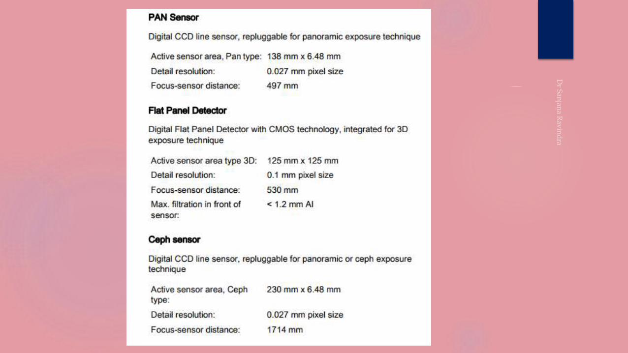
DIGITAL IMAGE RECEPTORS
CCD (charge coupled device) or
PSP (photostimulable storage phosphor)
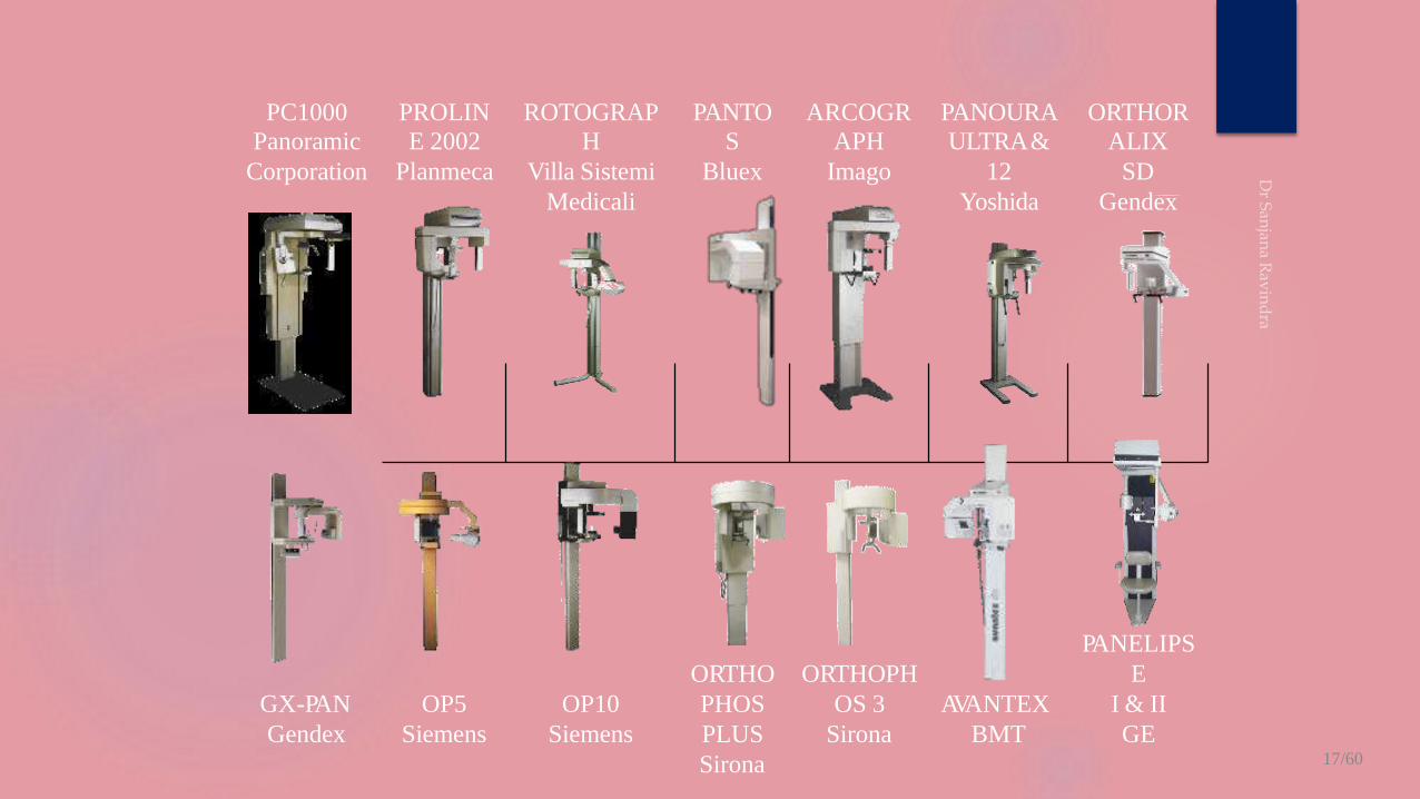
PC1000 PROLIN ROTOGRAP PANTO ARCOGR PANOURA ORTHOR
Panoramic E 2002 H S APH ULTRA& ALIX
Corporation Planmeca Villa Sistemi Bluex Imago 12 SD
Medicali Yoshida Gendex
GX-PAN
Gendex
OP5
Siemens
OP10
Siemens
ORTHO
PHOS
PLUS
Sirona
ORTHOPH
OS 3
Sirona
AVANTEX
BMT
PANELIPS
E
I & II
GE17/60

CONCEPTS
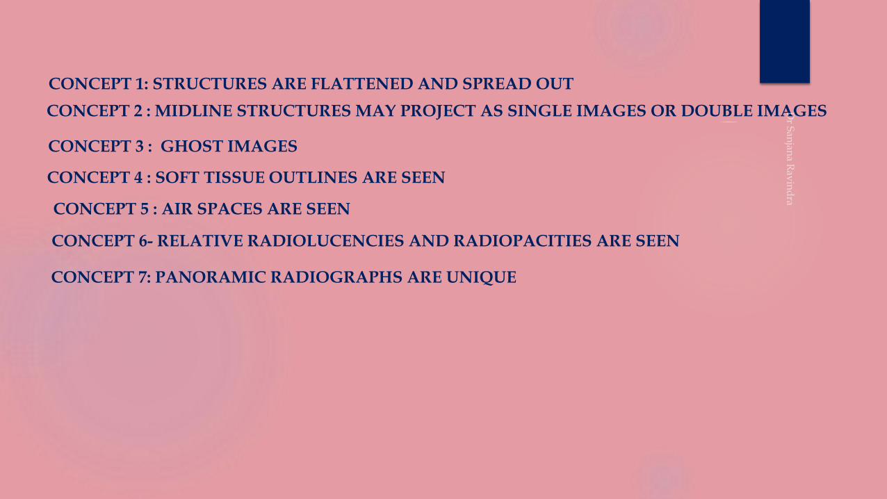
CONCEPT 1: STRUCTURES ARE FLATTENED AND SPREAD OUT
CONCEPT 2 : MIDLINE STRUCTURES MAY PROJECT AS SINGLE IMAGES OR DOUBLE IMAGES
CONCEPT 3 : GHOST IMAGES
CONCEPT 4 : SOFT TISSUE OUTLINES ARE SEEN
CONCEPT 5 : AIR SPACES ARE SEEN
CONCEPT 6- RELATIVE RADIOLUCENCIES AND RADIOPACITIES ARE SEEN
CONCEPT 7: PANORAMIC RADIOGRAPHS ARE UNIQUE
CONCEPTS IN PANORAMIC RADIOGRAPHY
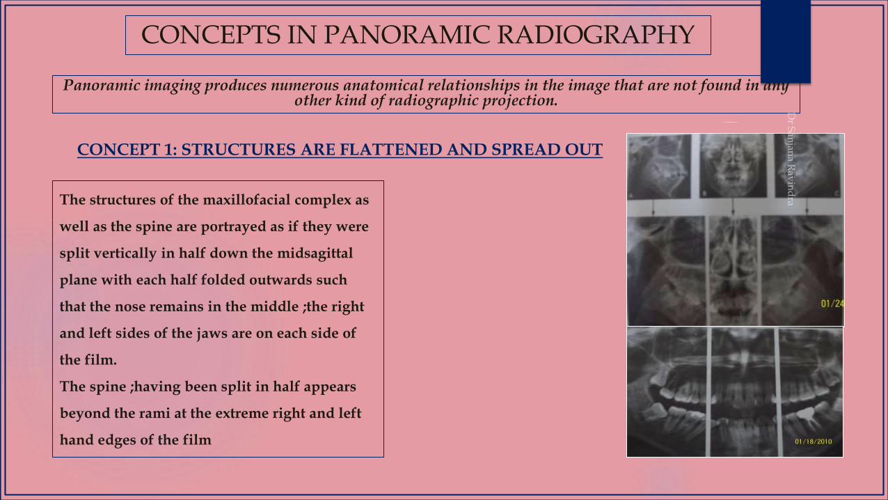
Panoramic imaging produces numerous anatomical relationships in the image that are not found in any other kind of radiographic projection.
The structures of the maxillofacial complex as
well as the spine are portrayed as if they were
split vertically in half down the midsagittal
plane with each half folded outwards such
that the nose remains in the middle ;the right
and left sides of the jaws are on each side of
the film.
The spine ;having been split in half appears
beyond the rami at the extreme right and left
hand edges of the film
CONCEPT 1: STRUCTURES ARE FLATTENED AND SPREAD OUT
The midline of the film corresponds to the anterior midline of the patient and right and left hand edges correspond to the posterior midline of the patient.
The right and left halves of the jaws and maxillofacial complex can be seen side by side on the film without one half being superimposed on the other.
DESIRABLE EFFECTS
UNDESIRABLE EFFECTS
Improper positioning of the patient in the machine.
Eg: when the chin is tipped too low and the patient is positioned little back in the machine ;the hyoid bone is spread out and projected up; right on top of the mandible.
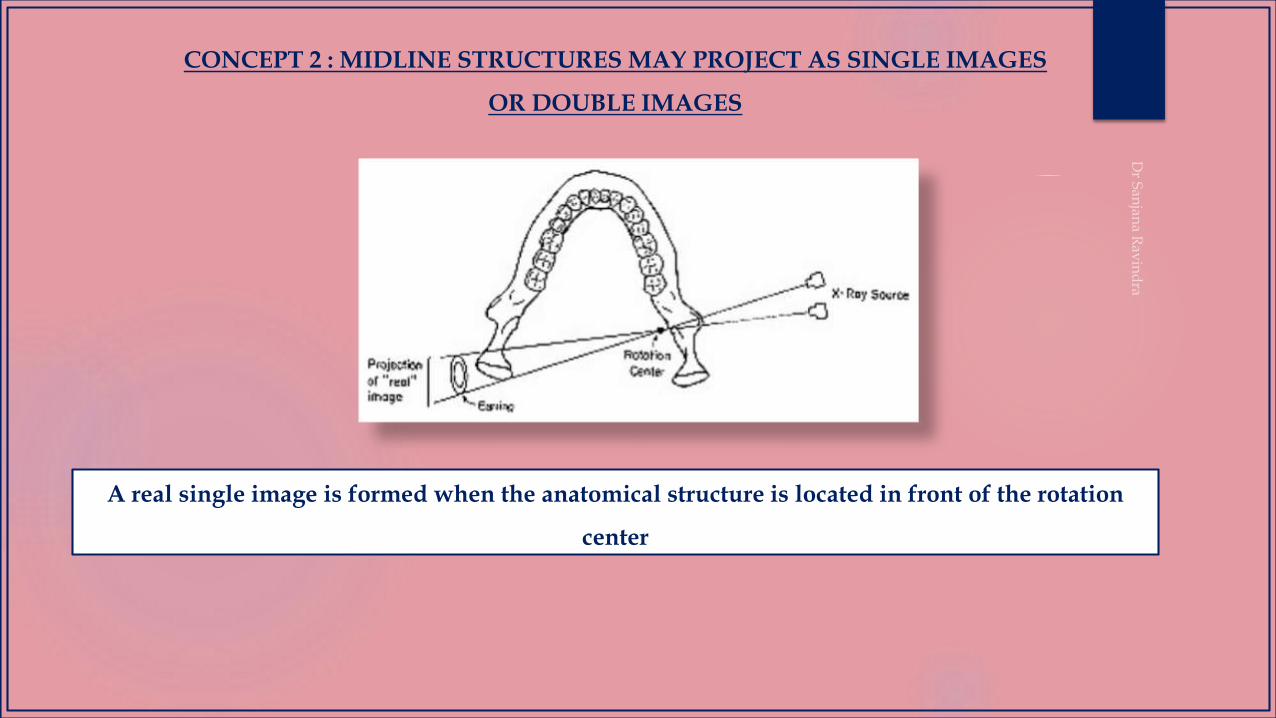
CONCEPT 2 : MIDLINE STRUCTURES MAY PROJECT AS SINGLE IMAGES
OR DOUBLE IMAGES
A real single image is formed when the anatomical structure is located in front of the rotation
center
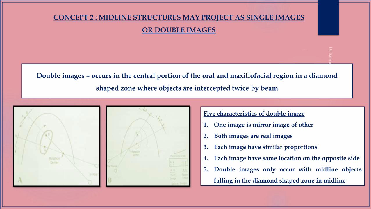
Double images – occurs in the central portion of the oral and maxillofacial region in a diamond
shaped zone where objects are intercepted twice by beam
Five characteristics of double image
1. One image is mirror image of other
2. Both images are real images
3. Each image have similar proportions
4. Each image have same location on the opposite side
5. Double images only occur with midline objects
falling in the diamond shaped zone in midline
CONCEPT 2 : MIDLINE STRUCTURES MAY PROJECT AS SINGLE IMAGES
OR DOUBLE IMAGES
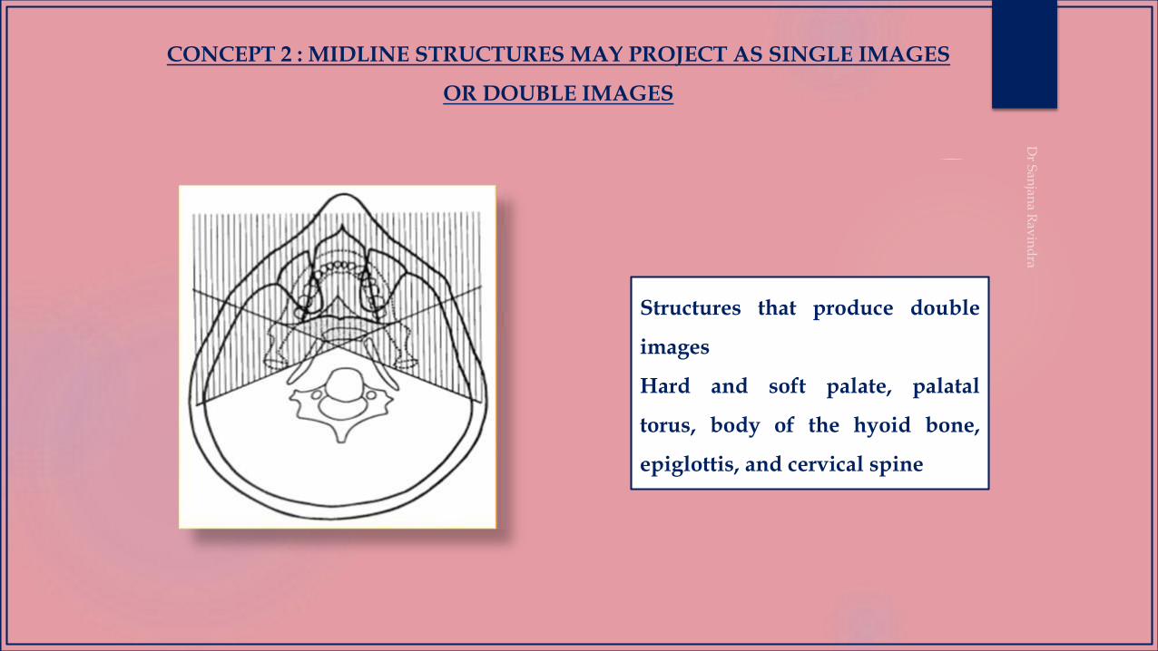
Structures that produce double
images
Hard and soft palate, palatal
torus, body of the hyoid bone,
epiglottis, and cervical spine
CONCEPT 2 : MIDLINE STRUCTURES MAY PROJECT AS SINGLE IMAGES
OR DOUBLE IMAGES
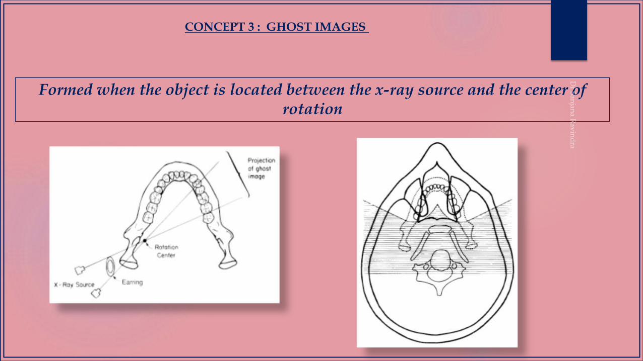
Formed when the object is located between the x-ray source and the center of rotation
CONCEPT 3 : GHOST IMAGES
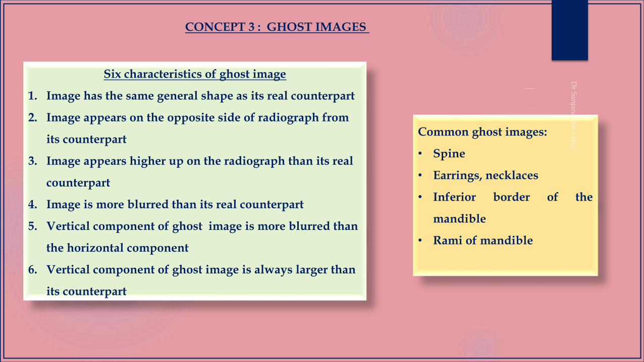
Six characteristics of ghost image
1. Image has the same general shape as its real counterpart
2. Image appears on the opposite side of radiograph from
its counterpart
3. Image appears higher up on the radiograph than its real
counterpart
4. Image is more blurred than its real counterpart
5. Vertical component of ghost image is more blurred than
the horizontal component
6. Vertical component of ghost image is always larger than
its counterpart
Common ghost images:
• Spine
• Earrings, necklaces
• Inferior border of the
mandible
• Rami of mandible
CONCEPT 3 : GHOST IMAGES
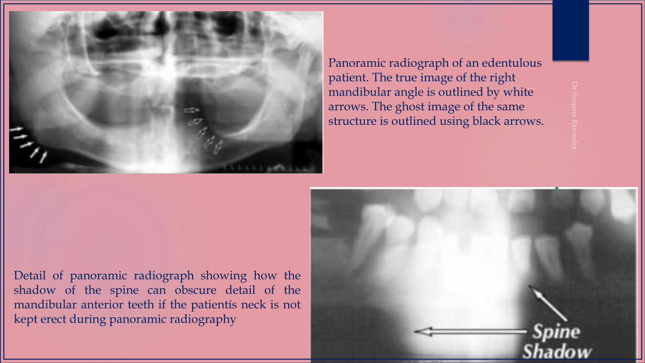
Panoramic radiograph of an edentulous patient. The true image of the right mandibular angle is outlined by white arrows. The ghost image of the same structure is outlined using black arrows.
Detail of panoramic radiograph showing how theshadow of the spine can obscure detail of themandibular anterior teeth if the patientís neck is notkept erect during panoramic radiography
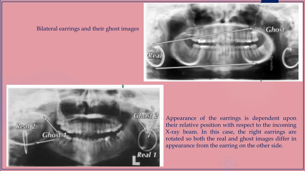
Bilateral earrings and their ghost images
Appearance of the earrings is dependent upontheir relative position with respect to the incomingX-ray beam. In this case, the right earrings arerotated so both the real and ghost images differ inappearance from the earring on the other side.
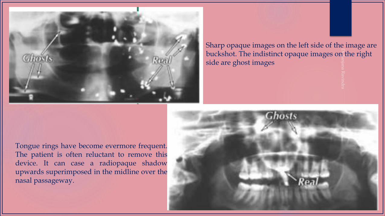
Sharp opaque images on the left side of the image are buckshot. The indistinct opaque images on the right side are ghost images
Tongue rings have become evermore frequent.The patient is often reluctant to remove thisdevice. It can case a radiopaque shadowupwards superimposed in the midline over thenasal passageway.
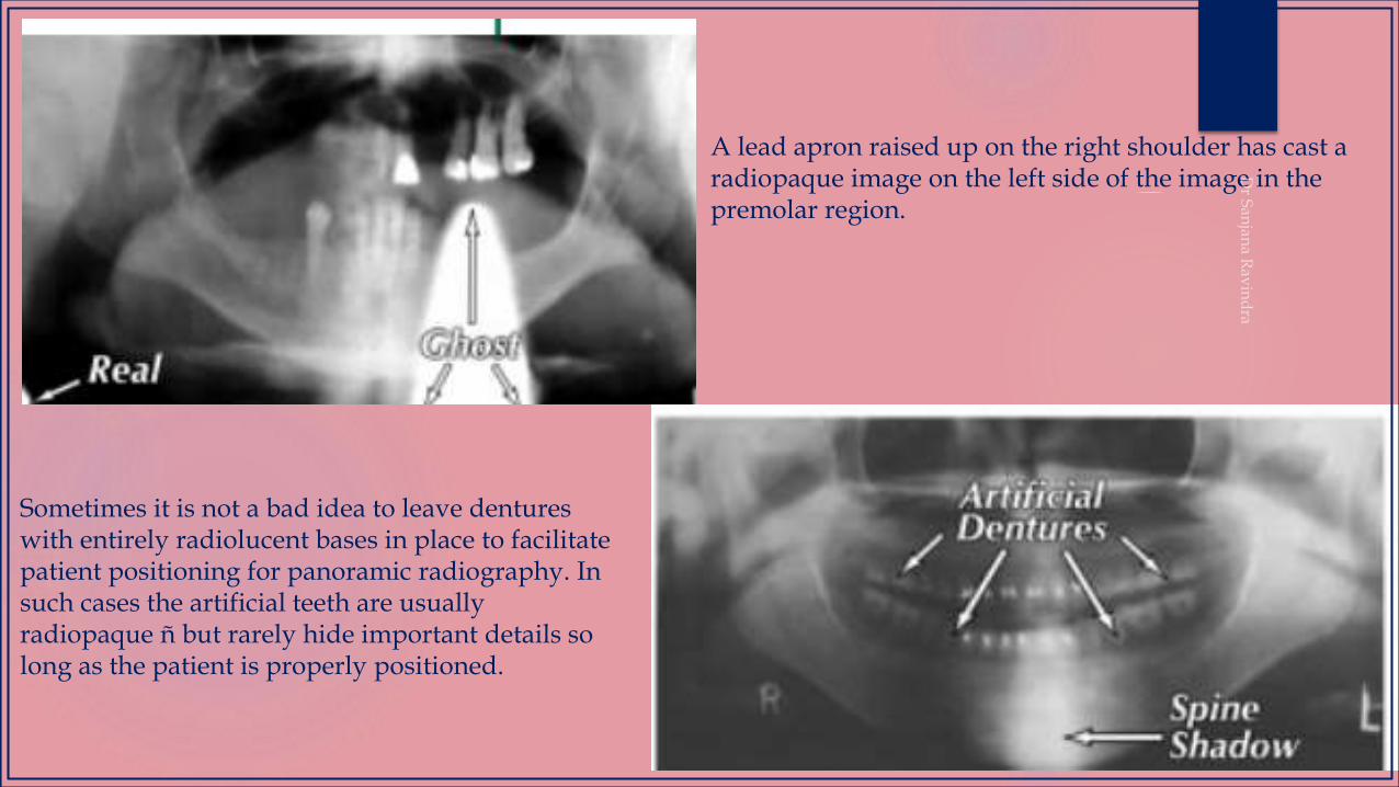
A lead apron raised up on the right shoulder has cast a radiopaque image on the left side of the image in the premolar region.
Sometimes it is not a bad idea to leave dentures with entirely radiolucent bases in place to facilitate patient positioning for panoramic radiography. In such cases the artificial teeth are usually radiopaque ñ but rarely hide important details so long as the patient is properly positioned.
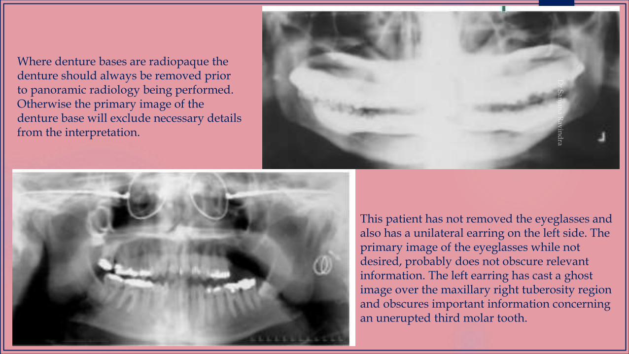
Where denture bases are radiopaque the denture should always be removed prior to panoramic radiology being performed. Otherwise the primary image of the denture base will exclude necessary details from the interpretation.
This patient has not removed the eyeglasses and also has a unilateral earring on the left side. The primary image of the eyeglasses while not desired, probably does not obscure relevant information. The left earring has cast a ghost image over the maxillary right tuberosity region and obscures important information concerning an unerupted third molar tooth.
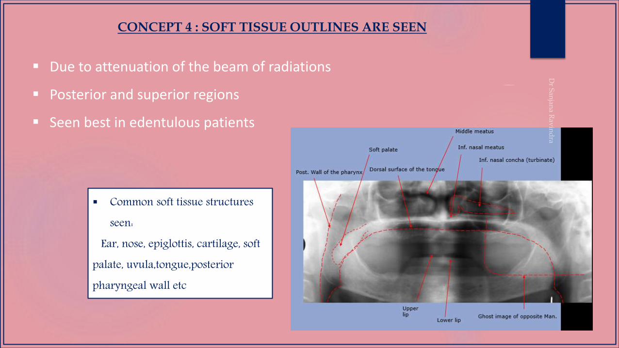
CONCEPT 4 : SOFT TISSUE OUTLINES ARE SEEN
Due to attenuation of the beam of radiations
Posterior and superior regions
Seen best in edentulous patients
Common soft tissue structures seen:
Ear, nose, epiglottis, cartilage, soft palate, uvula,tongue,posteriorpharyngeal wall etc
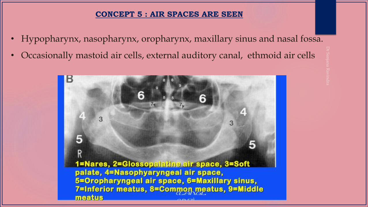
CONCEPT 5 : AIR SPACES ARE SEEN
• Hypopharynx, nasopharynx, oropharynx, maxillary sinus and nasal fossa.
• Occasionally mastoid air cells, external auditory canal, ethmoid air cells
CONCEPT 6- RELATIVE RADIOLUCENCIES AND RADIOPACITIES ARE SEEN
• Important to separate shadows originating from machine and
patient
• In patient - 3 basic components –hard tissue(teeth and bone),
soft tissue (including cartilage and fluid) and air
CONCEPT 7: PANORAMIC RADIOGRAPHS ARE UNIQUE
• Interpretive potential is more than full mouth iopar
• Interrelationship of structures are more accurate
• Excellent resource in patients with trismus and trauma
• Excellent projection of variety of structures in a single film

PROCEDURE
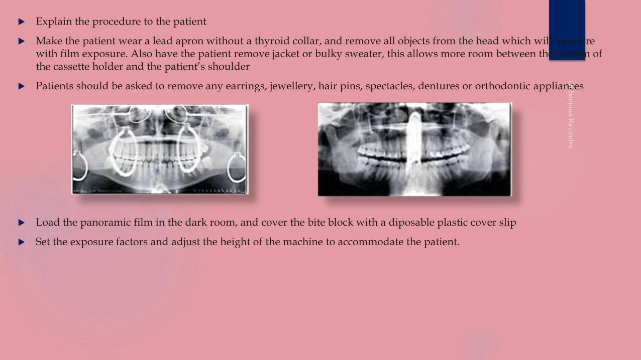
Explain the procedure to the patient
Make the patient wear a lead apron without a thyroid collar, and remove all objects from the head which will interfere with film exposure. Also have the patient remove jacket or bulky sweater, this allows more room between the bottom of the cassette holder and the patient’s shoulder
Patients should be asked to remove any earrings, jewellery, hair pins, spectacles, dentures or orthodontic appliances
Load the panoramic film in the dark room, and cover the bite block with a diposable plastic cover slip
Set the exposure factors and adjust the height of the machine to accommodate the patient.
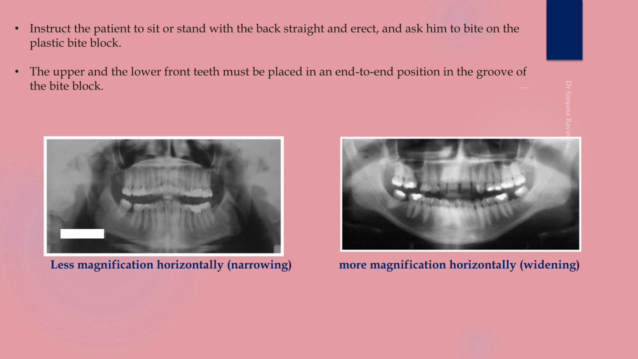
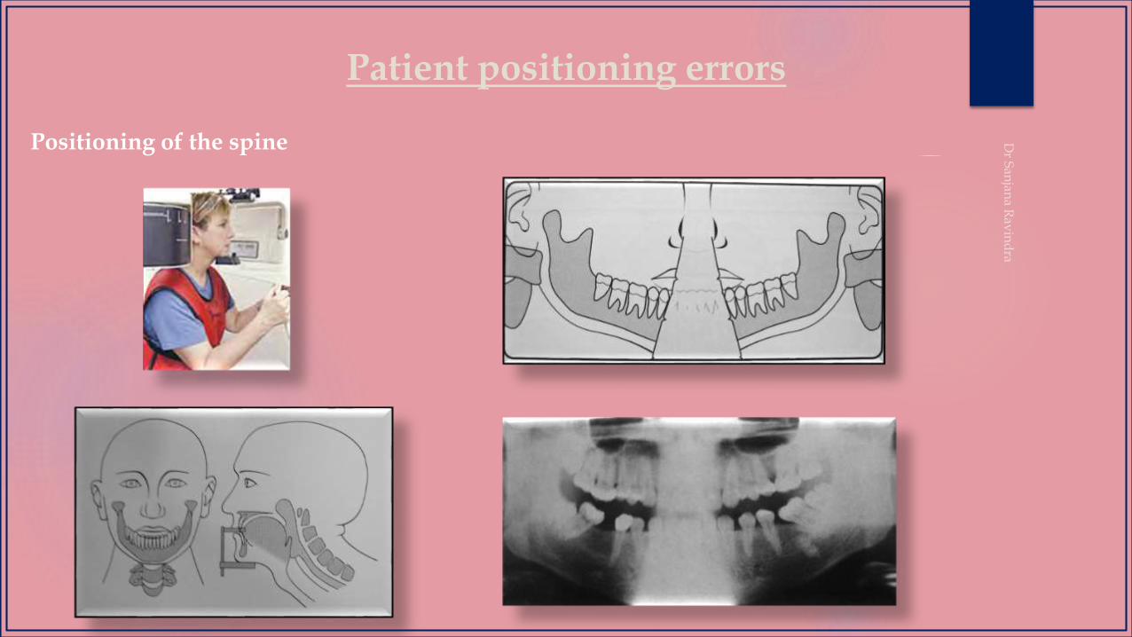
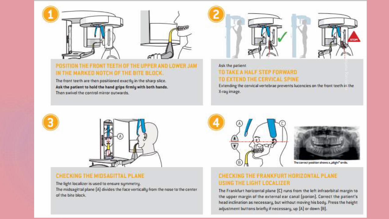
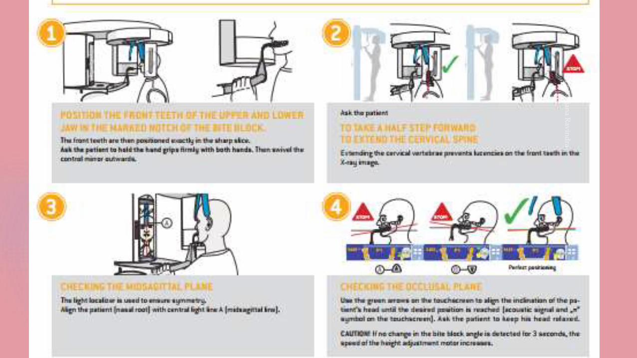
• Instruct the patient to sit or stand with the back straight and erect, and ask him to bite on the plastic bite block.
• The upper and the lower front teeth must be placed in an end-to-end position in the groove of the bite block.
Less magnification horizontally (narrowing) more magnification horizontally (widening)
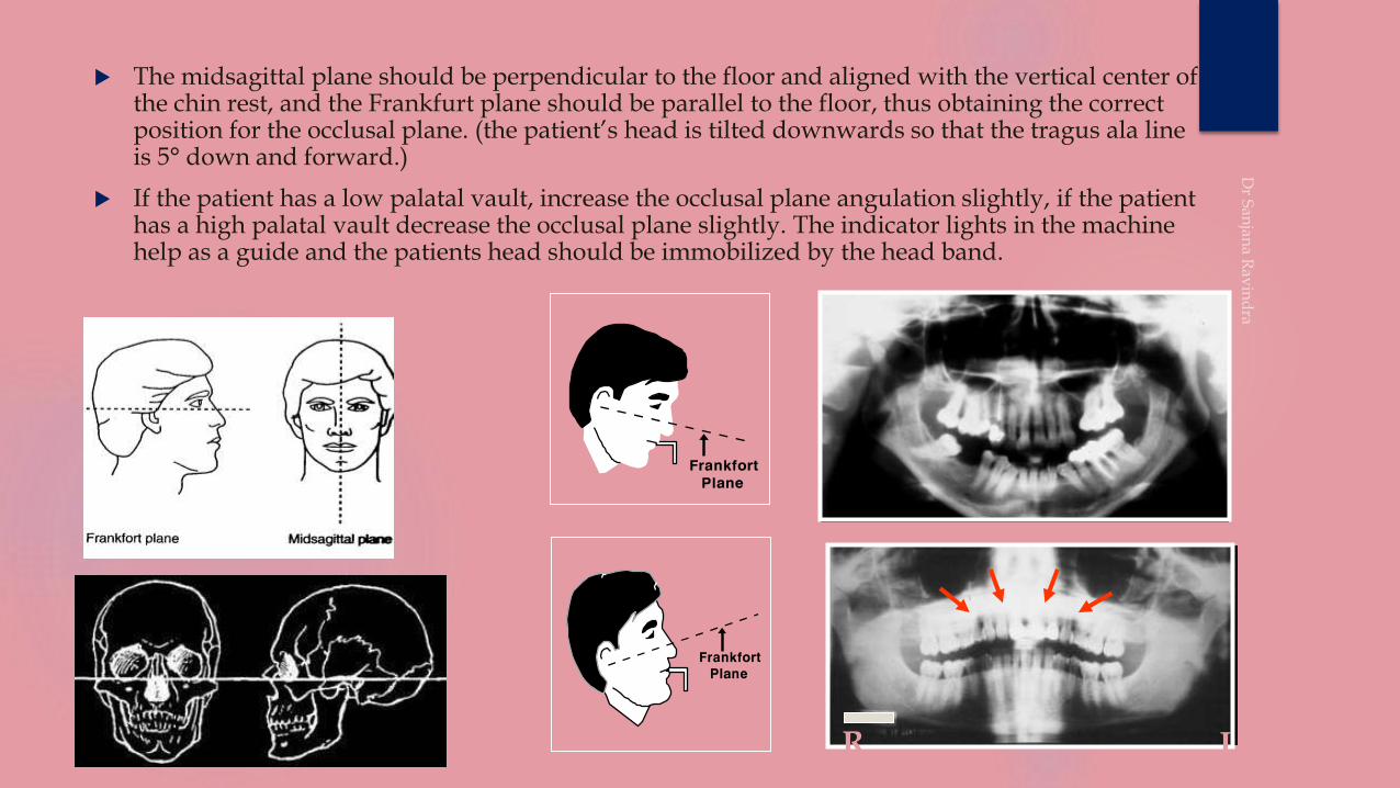
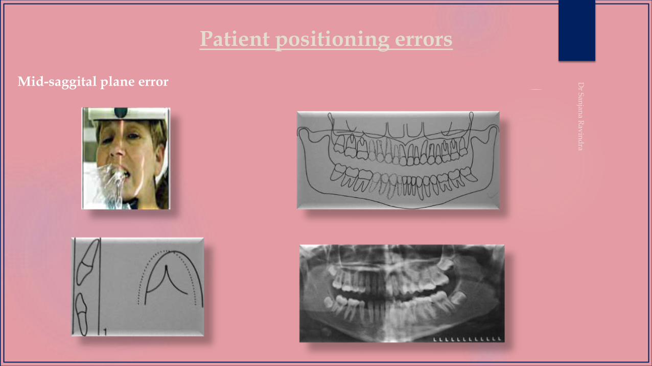
The midsagittal plane should be perpendicular to the floor and aligned with the vertical center of the chin rest, and the Frankfurt plane should be parallel to the floor, thus obtaining the correct position for the occlusal plane. (the patient’s head is tilted downwards so that the tragus ala line is 5° down and forward.)
If the patient has a low palatal vault, increase the occlusal plane angulation slightly, if the patient has a high palatal vault decrease the occlusal plane slightly. The indicator lights in the machine help as a guide and the patients head should be immobilized by the head band.
R L
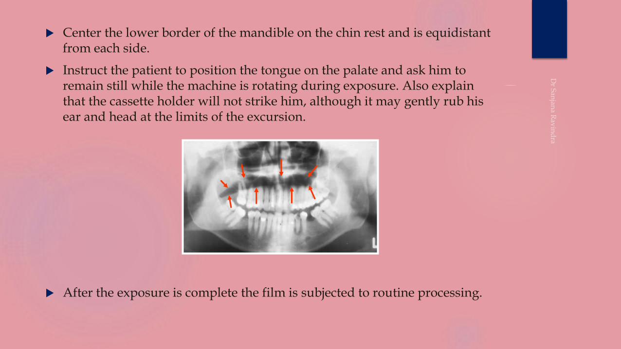
Center the lower border of the mandible on the chin rest and is equidistant from each side.
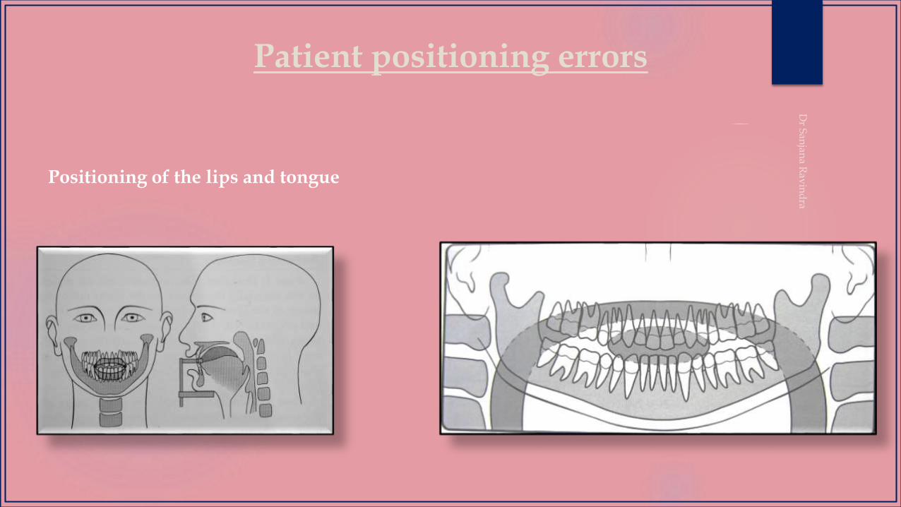
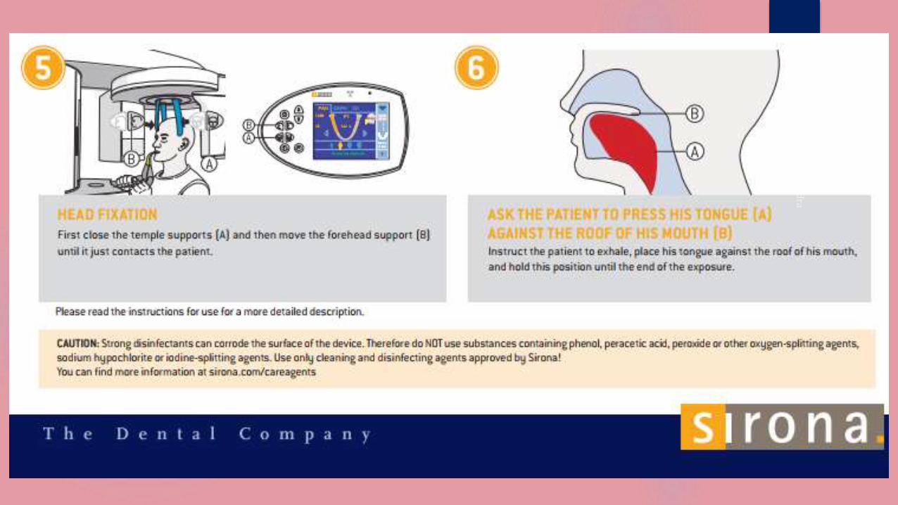
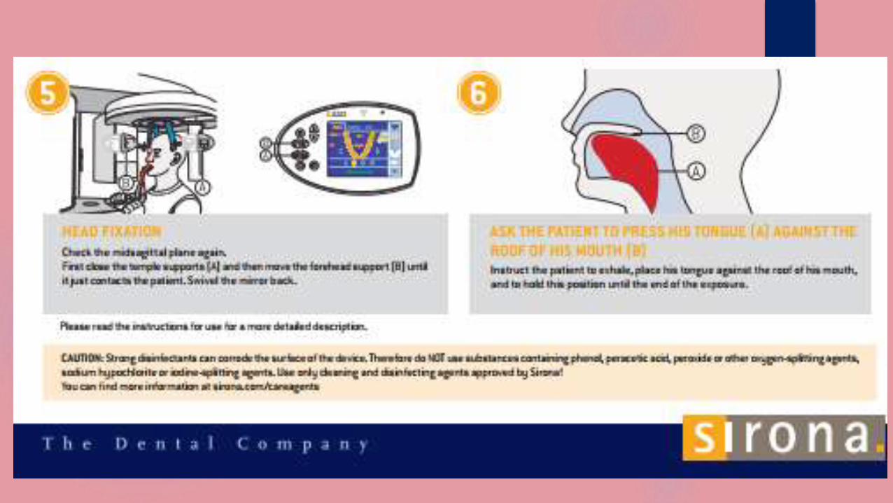
Instruct the patient to position the tongue on the palate and ask him to remain still while the machine is rotating during exposure. Also explain that the cassette holder will not strike him, although it may gently rub his ear and head at the limits of the excursion.
After the exposure is complete the film is subjected to routine processing.
CLINICAL INDICATIONS
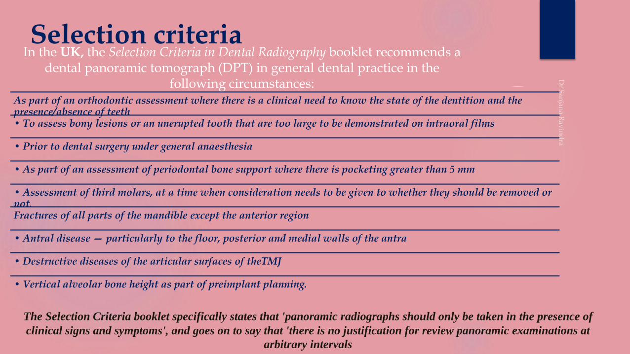
Selection criteriaIn the UK, the Selection Criteria in Dental Radiography booklet recommends a
dental panoramic tomograph (DPT) in general dental practice in the following circumstances:
As part of an orthodontic assessment where there is a clinical need to know the state of the dentition and the presence/absence of teeth • To assess bony lesions or an unerupted tooth that are too large to be demonstrated on intraoral films
• Prior to dental surgery under general anaesthesia
• As part of an assessment of periodontal bone support where there is pocketing greater than 5 mm
• Assessment of third molars, at a time when consideration needs to be given to whether they should be removed or not.Fractures of all parts of the mandible except the anterior region
• Antral disease — particularly to the floor, posterior and medial walls of the antra
• Destructive diseases of the articular surfaces of theTMJ
• Vertical alveolar bone height as part of preimplant planning.
The Selection Criteria booklet specifically states that 'panoramic radiographs should only be taken in the presence of
clinical signs and symptoms', and goes on to say that 'there is no justification for review panoramic examinations at
arbitrary intervals
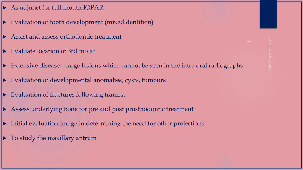
As adjunct for full mouth IOPAR
Evaluation of tooth development (mixed dentition)
Assist and assess orthodontic treatment
Evaluate location of 3rd molar
Extensive disease – large lesions which cannot be seen in the intra oral radiographs
Evaluation of developmental anomalies, cysts, tumours
Evaluation of fractures following trauma
Assess underlying bone for pre and post prosthodontic treatment
Initial evaluation image in determining the need for other projections
To study the maxillary antrum

ADVANTAGES
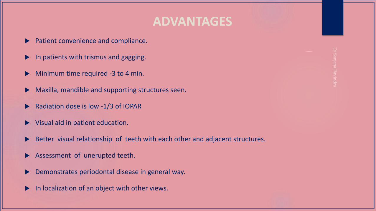
ADVANTAGES Patient convenience and compliance.
In patients with trismus and gagging.
Minimum time required -3 to 4 min.
Maxilla, mandible and supporting structures seen.
Radiation dose is low -1/3 of IOPAR
Visual aid in patient education.
Better visual relationship of teeth with each other and adjacent structures.
Assessment of unerupted teeth.
Demonstrates periodontal disease in general way.
In localization of an object with other views.
/60

DISADVANTAGES/ LIMITATIONS
DISADVANTAGES
Does not display fine anatomic details
Does not display fine carious lesions, periapical disease, fine structures of
periodontium.
Proximal surface of premolars overlap
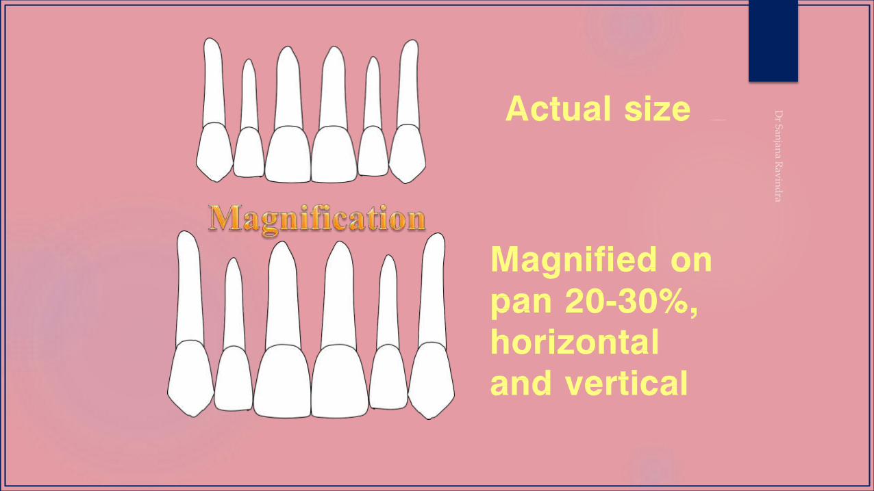
Unequal magnification and geometric distortion
Presence of overlapping structures like spine.
Clinically important objects outside the line of focus distorted or not present
NORMAL PANORAMIC
ANATOMY
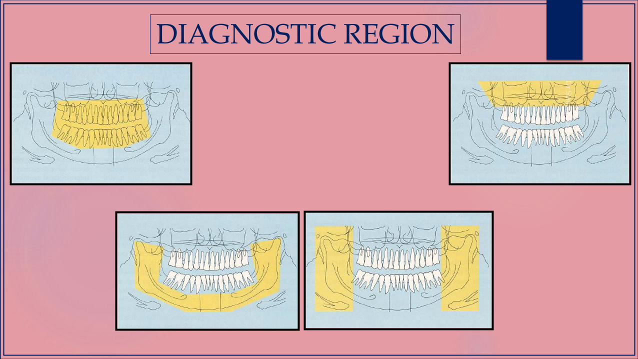
DIAGNOSTIC REGION
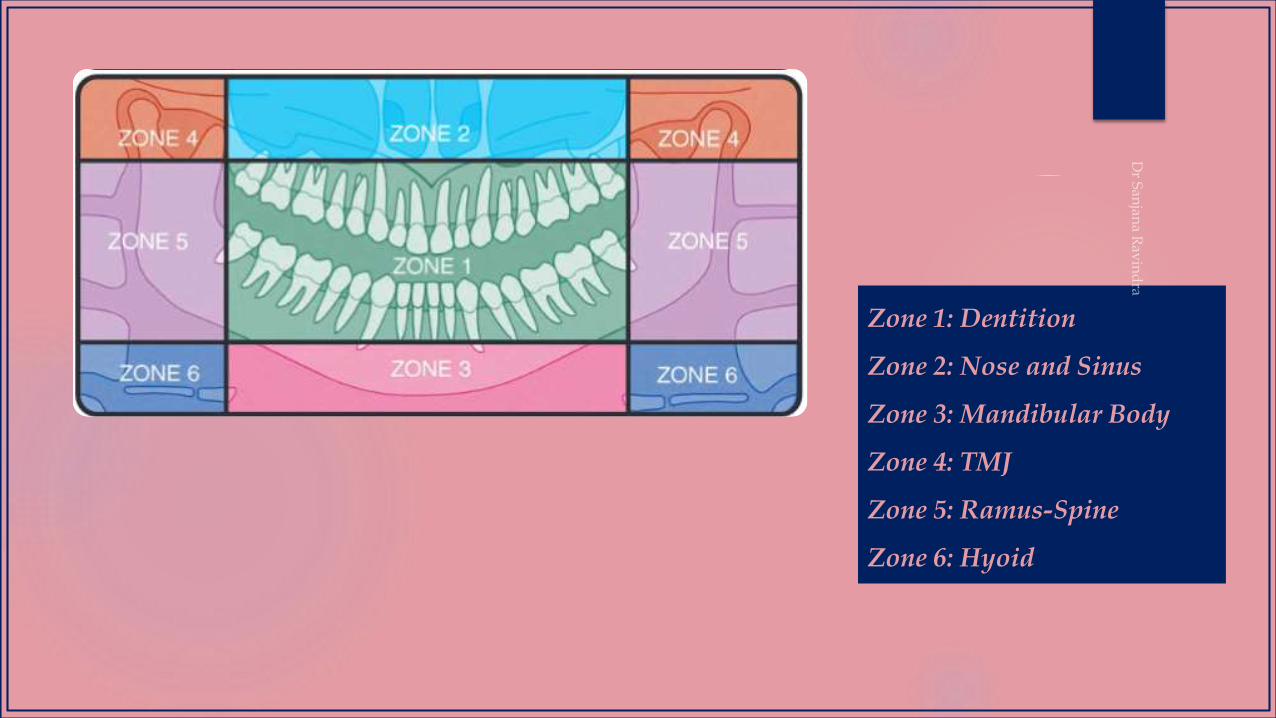
Zone 1: Dentition
Zone 2: Nose and Sinus
Zone 3: Mandibular Body
Zone 4: TMJ
Zone 5: Ramus-Spine
Zone 6: Hyoid
1
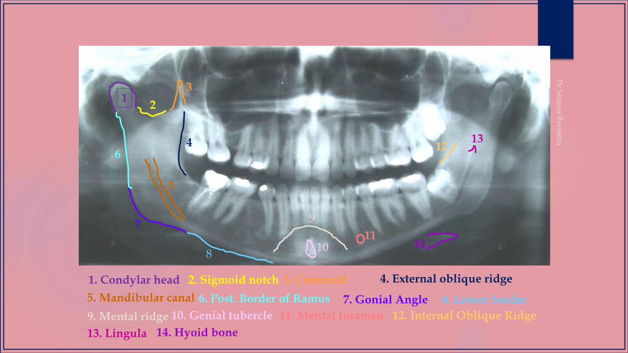
1. Condylar head 2. Sigmoid notch 3. Coronoid 4. External oblique ridge
5. Mandibular canal
2
3
4
5
6. Post. Border of Ramus 8. Lower border7. Gonial Angle
6
7
9. Mental ridge 11. Mental foramen 10. Genial tubercle
13. Lingula
12. Internal Oblique Ridge
14. Hyoid bone
8
9
1011
1213
15
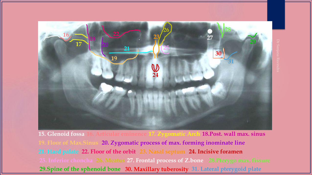
15. Glenoid fossa
19. Floor of Max.Sinus
17. Zygomatic Arch16. Articular eminence 18.Post. wall max. sinus
20. Zygomatic process of max. forming inominate line
21. Hard palate 22. Floor of the orbit 23. Nasal septum 24. Incisive foramen
25. Inferior choncha 26. Meatus 27. Frontal process of Z.bone
16
1718
19
2021
2223
2925
24
26
28.Pterygo max. fissure
30. Maxillary tuberosity29.Spine of the sphenoid bone 31. Lateral pterygoid plate
31
30
28
27
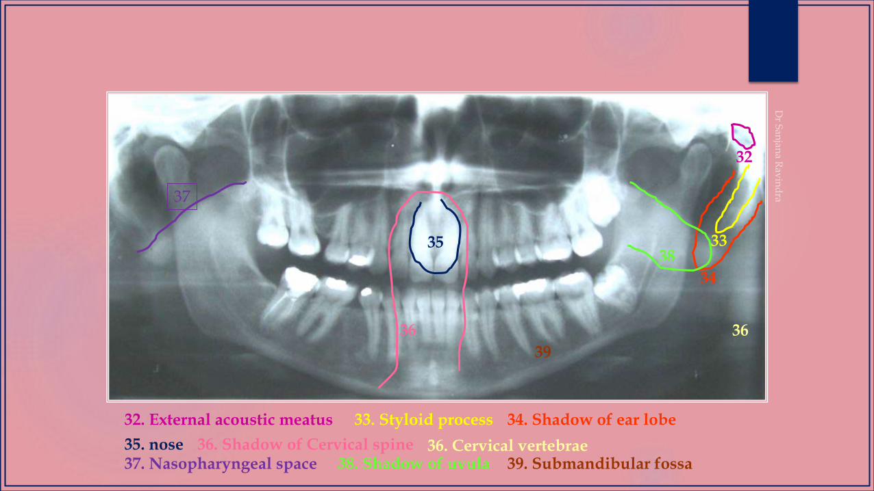
32
32. External acoustic meatus 34. Shadow of ear lobe33. Styloid process
35. nose 36. Shadow of Cervical spine
33
34
35
36 36
36. Cervical vertebrae
37
37. Nasopharyngeal space 38. Shadow of uvula
39
38
39. Submandibular fossa
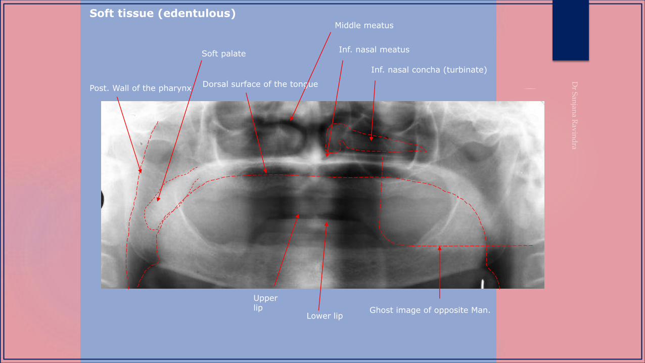
Inf. nasal concha (turbinate)
Inf. nasal meatus
Dorsal surface of the tonguePost. Wall of the pharynx
Soft palate
Lower lip
Upper lip
Middle meatus
Ghost image of opposite Man.
Soft tissue (edentulous)

COMMON ERRORS
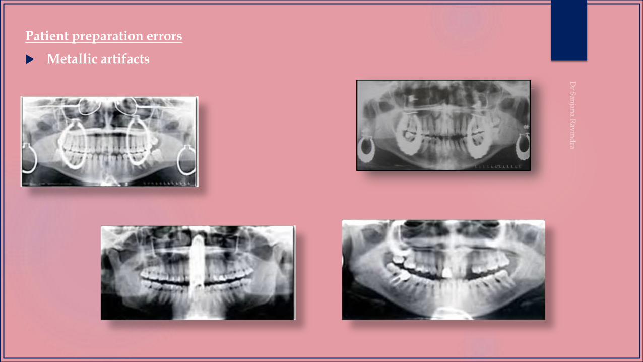
Patient preparation errors
Metallic artifacts
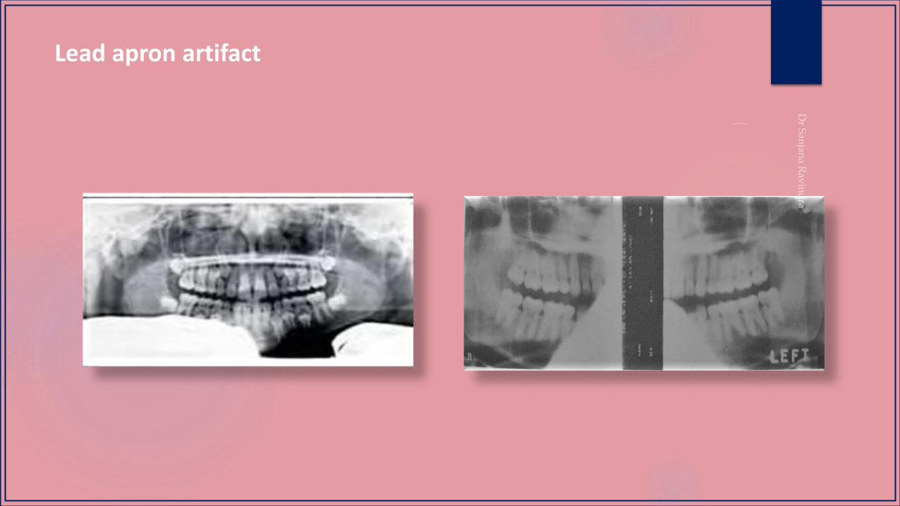
Lead apron artifact
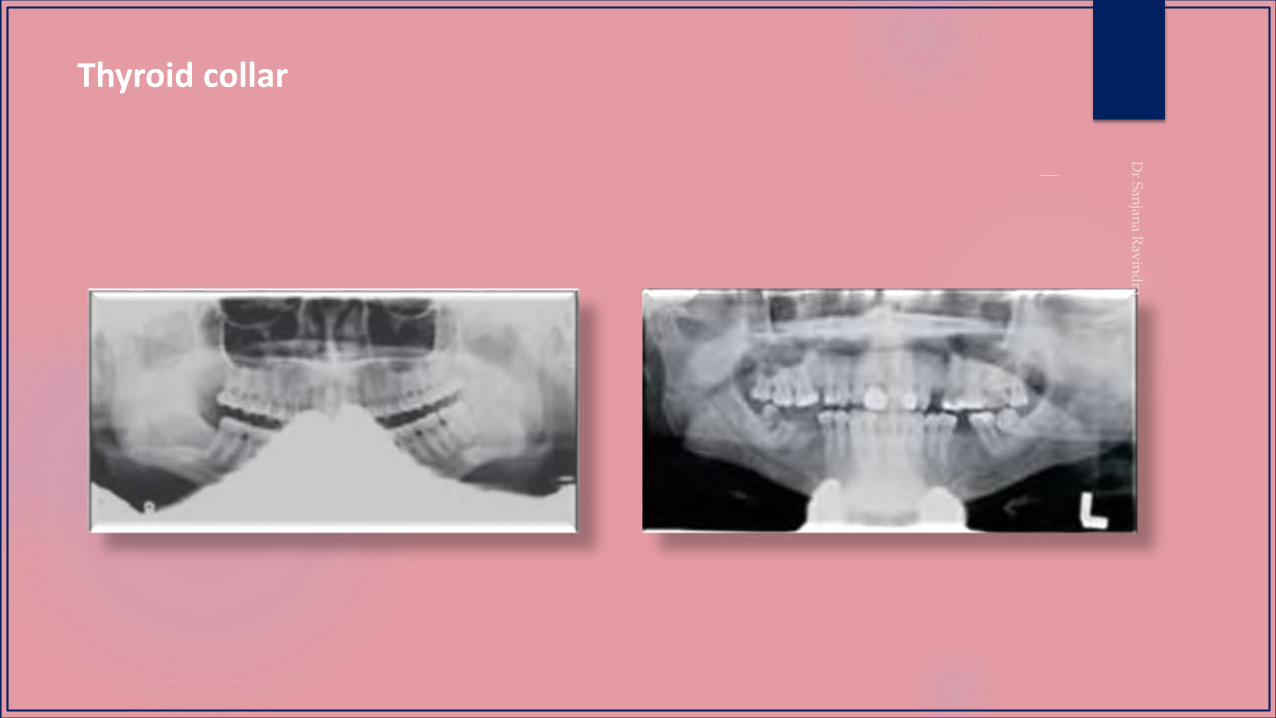
Thyroid collar
Patient positioning errors
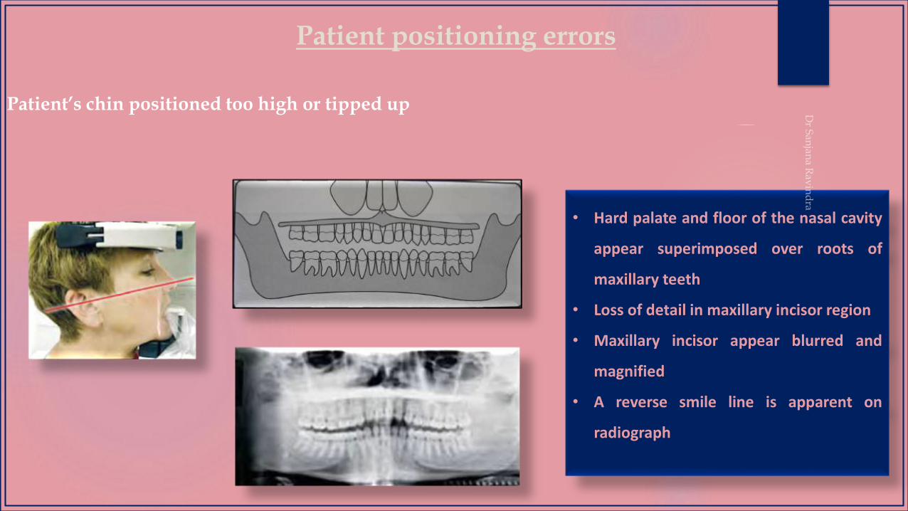
Patient’s chin positioned too high or tipped up
• Hard palate and floor of the nasal cavity
appear superimposed over roots of
maxillary teeth
• Loss of detail in maxillary incisor region
• Maxillary incisor appear blurred and
magnified
• A reverse smile line is apparent on
radiograph
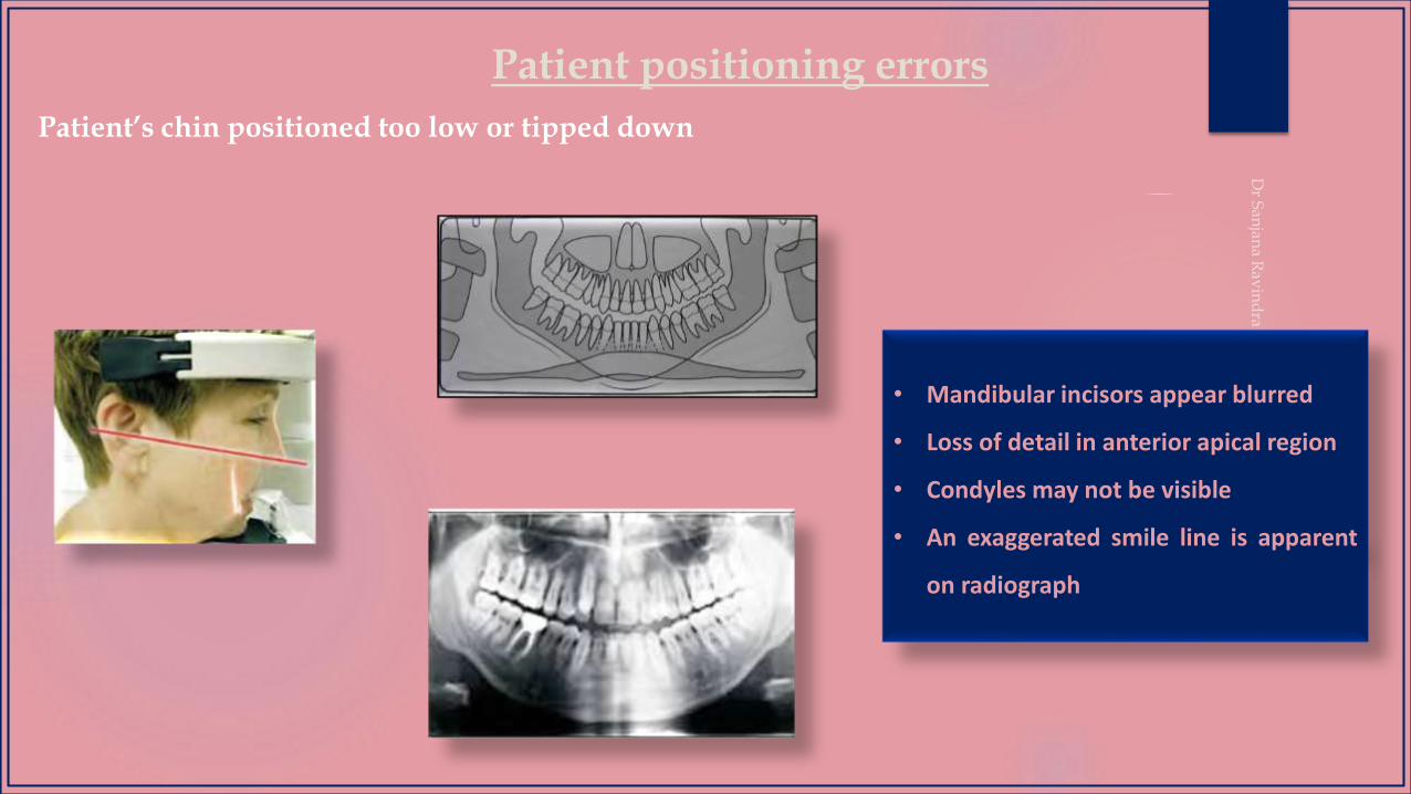
Patient positioning errors
Patient’s chin positioned too low or tipped down
• Mandibular incisors appear blurred
• Loss of detail in anterior apical region
• Condyles may not be visible
• An exaggerated smile line is apparent
on radiograph
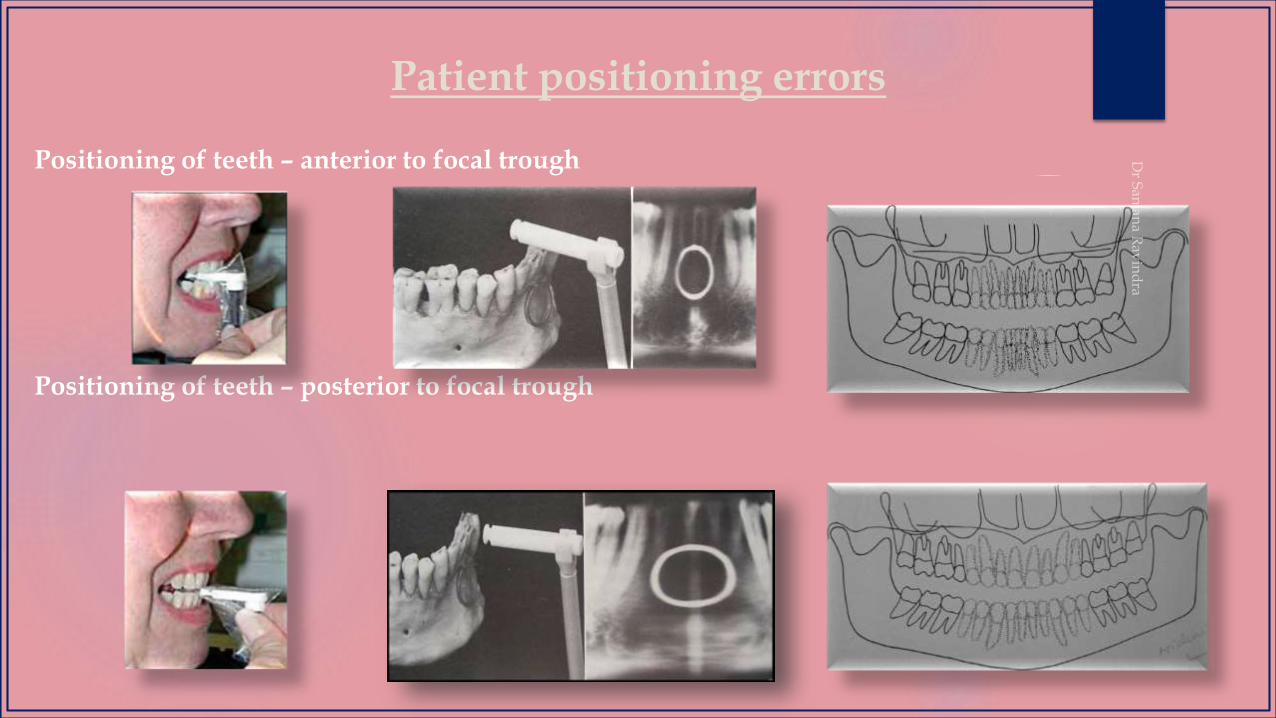
Patient positioning errors
Positioning of teeth – anterior to focal trough
Positioning of teeth – posterior to focal trough
Patient positioning errors
Mid-saggital plane error
Patient positioning errors
Positioning of the spine
Patient positioning errors
Positioning of the lips and tongue
Patient positioning errors
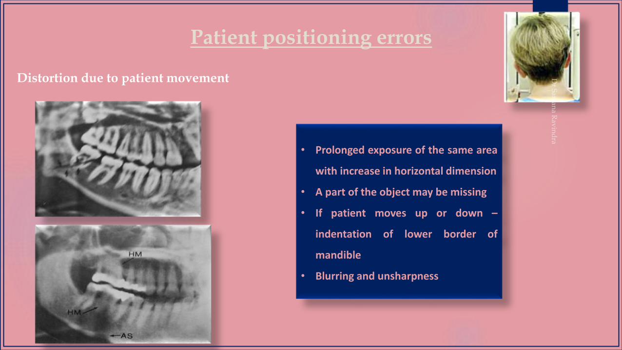
Distortion due to patient movement
• Prolonged exposure of the same area
with increase in horizontal dimension
• A part of the object may be missing
• If patient moves up or down –
indentation of lower border of
mandible
• Blurring and unsharpness
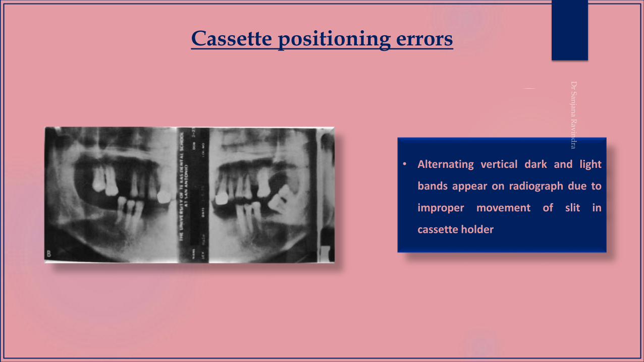
Cassette positioning errors
• Alternating vertical dark and light
bands appear on radiograph due to
improper movement of slit in
cassette holder
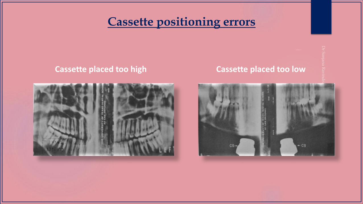
Cassette positioning errors
Cassette placed too high Cassette placed too low
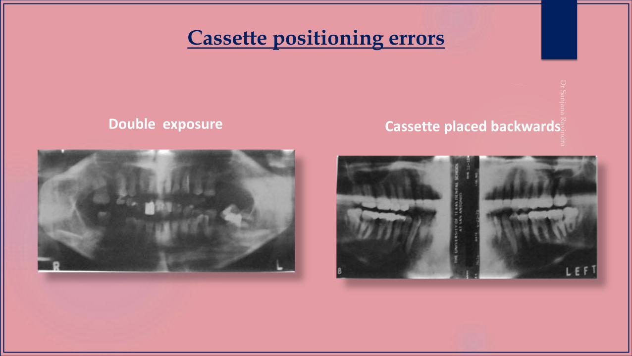
Cassette positioning errors
Double exposure Cassette placed backwards
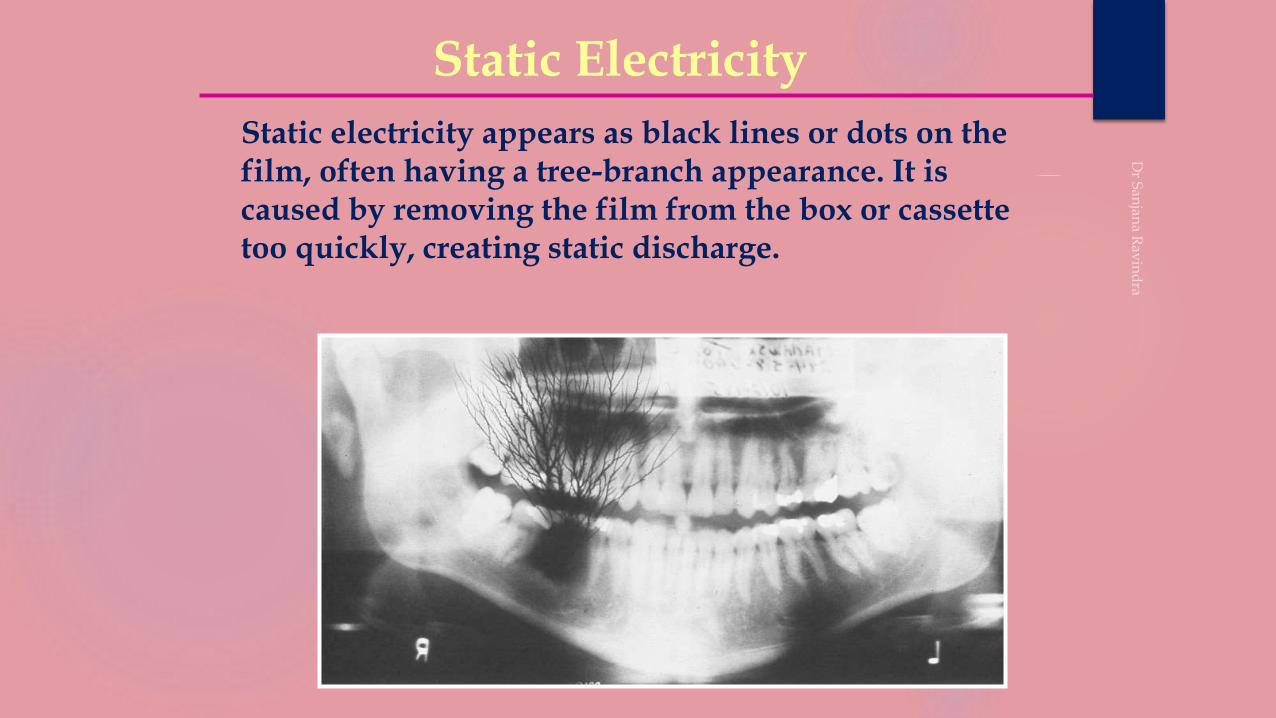
Static electricity appears as black lines or dots on the film, often having a tree-branch appearance. It is caused by removing the film from the box or cassette too quickly, creating static discharge.
Static Electricity
Static Electricity
R L
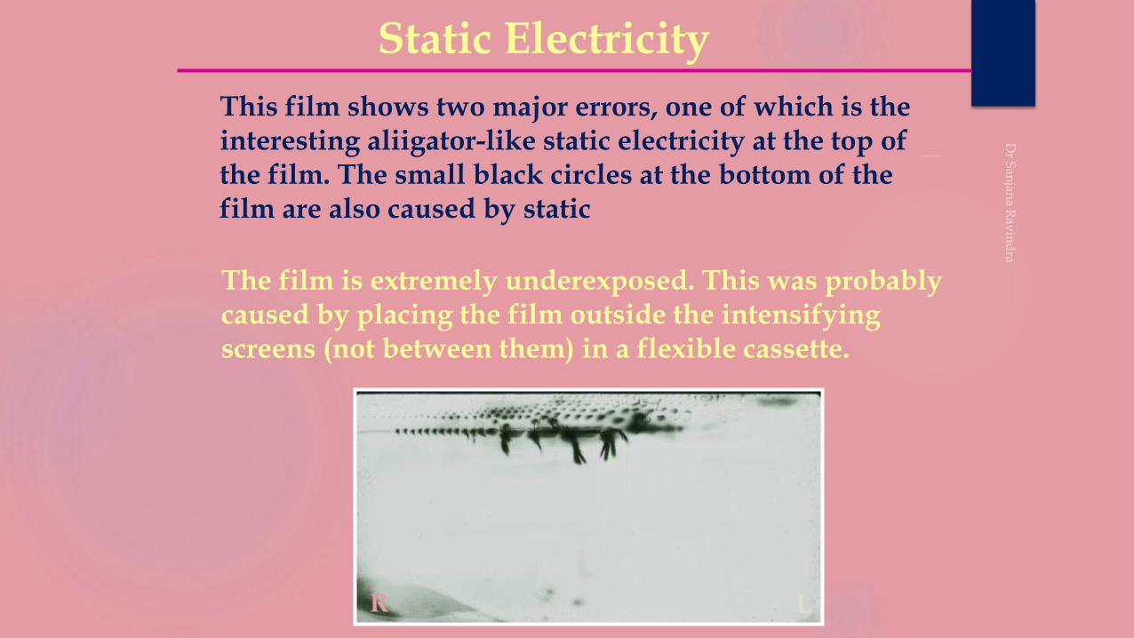
This film shows two major errors, one of which is the interesting aliigator-like static electricity at the top of the film. The small black circles at the bottom of the film are also caused by static
The film is extremely underexposed. This was probably caused by placing the film outside the intensifying screens (not between them) in a flexible cassette.
ERRORS IN FILM EXPOSURE & DEVELOPMENT
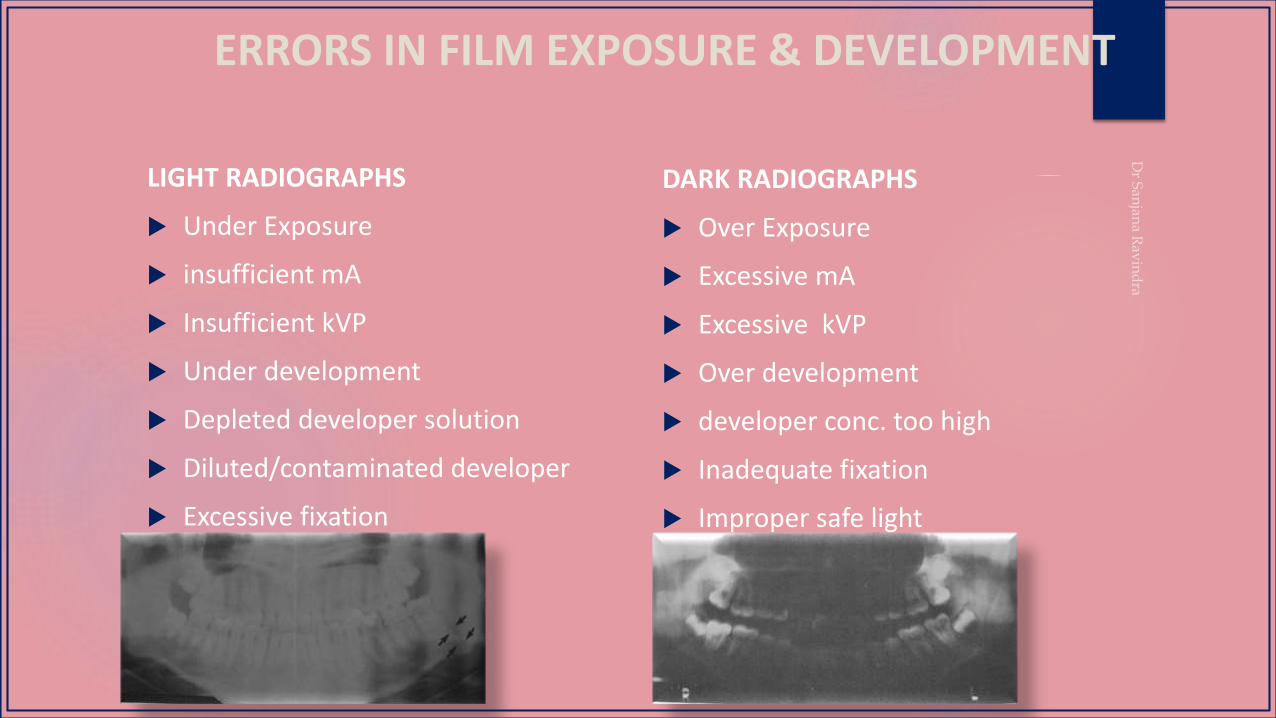
LIGHT RADIOGRAPHS
Under Exposure
insufficient mA
Insufficient kVP
Under development
Depleted developer solution
Diluted/contaminated developer
Excessive fixation
DARK RADIOGRAPHS
Over Exposure
Excessive mA
Excessive kVP
Over development
developer conc. too high
Inadequate fixation
Improper safe light

MODIFICATION
Reverse Panoral Radiograph
Disadvantages
• Positioning of the patient is critical and difficult.
• Exposure to the eyes is more.
This technique of reverse panoral
radiography is one way in which a
panoramic X-ray machine is used to
provide a clearer and less distorted view
of the ascending ramus and it’s process
and the adjacent structures with the
mouth open or closed.
Computed Panoramic Tomography with Scanner Simulated Luminescence
Images obtained by panoramic tomography are characteristically blurred and not detailed enough to show fine bony abnormalities.
This new computed system is used to temporarily store the X-ray energy pattern.
The image receptor converts the latent image into digital signals which are processed and recorded onto the film.
Advantages
1. Reduced radiation exposure.
2. Better diagnostic quality.
3. Contrast and spatial frequency enhancement

DEPARTMENT LIBRARY

DEPARTMENT OF ORAL MEDICINE AND RADIOLOGY (RRDCH)
CONVENTIONAL DIGITAL
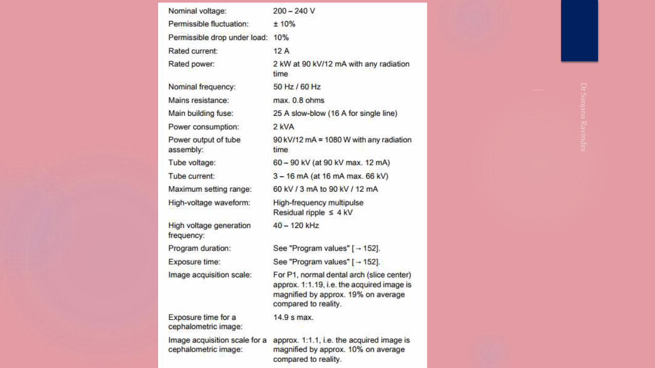
kVp – 60-90
mA - 3-16
Focal spot – 0.5mm
Magnification – 19% (1:1.19)
kVp – 85
mA - 10
Focal spot – 0.5mm
Magnification – 20% (1:1.2)


REFERENCES
REFERENCES
1. Rondon RHN , Pereira YCL , do Nascimento GC.Imaging Sci Dent 2014; 44 : 1-6.
2. Newadkar UR, Chaudhari L, Khalekar YK. Common errors on panoramic radiograph: A time to reflect and review and not to sweep them under the carpet!. SRM J Res
Dent Sci 2016;7:146-9.
3. Langland OE, Langlais RP, McDavid WD, Del Balso AM. Normal panoramic anatomy. In: Langland OE, Langlais RP, McDavid WD, Del Balso AM (eds). Panoramic
Radiology (2nd edn). Philadelphia: Lea & Febiger, 1989, pp 183–223.
4. Langland OE, Langlais RP, McDavid WD, Del Balso AM. Characteristics of different panoramic machines. In: Langland OE, Langlais RP, McDavid WD, Del Balso AM
(eds). Panoramic Radiology (2nd edn). Philadelphia: Lea & Febiger, 1989, pp 76–101.
5. Langland OE, Langlais RP, McDavid WD, Del Balso AM. Trouble shooting errors in panoramic techniques. In: Langland OE, Langlais RP, McDavid WD, Del Balso AM
(eds). Panoramic Radiology (2nd edn). Philadelphia: Lea and Febiger, 1989, pp 224–272.
6. Monsour PA, Mendoza AR. Panoramic ghost images as an aid in the localization of soft tissue calcifications. Oral Surg Oral Med Oral Pathol 1990; 69: 748–756.
7. Kaugars GE, Collet WK. Panoramic ghosts. Oral Surg Oral Med Oral Pathol 1987; 63: 103–108.
8. White S C, Pharoah M J. Oral Radiology Principles and Interpretation, 6th Ed. Mosby. 2006;175-190
9. Karjodkar F R. Textbook of Dental and Maxillofacial Radiology, 2st Ed. Jaypee Brothers Medical Publishers (P) Ltd. 2006:206-222
10. Haring JI, Jansen L. Dental Radiography Principles and Techniques, 2nd Ed. W. B. Saunders Company. 2001;125-130
11. Langland O, Langlais R P, Preece J W. Principles of Dental Imaging, 2nd Ed. Lippincott Williams & Wilkins. 2002:201-258.
12. Waites E. Essentials of Dental Radiography and Radiology, 3rd Ed. Churchill Livingstone. 2003: 161-176
13. Rushton VE, Rout J. Panoramic Radiology. Quintessentials publishing Co. Ltd London, 2006:2-67
14. Goaz PW, White SC. Oral radiology Principles and Interpretation 2nded.New Dehli B.I. Publications;1998:314-337