PanelView Component HMI Terminals · Installation Instructions PanelView Component HMI Terminals...
36
Installation Instructions PanelView Component HMI Terminals Catalog Numbers 2711C-F2M, 2711C-K2M, 2711C-T3M, 2711C-K3M, 2711C-T6M, 2711C-T4T, 2711C-T6C, 2711C-T6T, 2711C-T10C About This Publication This document provides instructions on how to install, wire, ground, and troubleshoot PanelView Component HMI terminals. It does not provide information on how to configure or run applications on the following devices: 2711C-F2M, 2711C-K2M, 2711C-T3M, 2711C-K3M, 2711C-T6M, 2711C-T4T, 2711C-T6C, 2711C-T6T, 2711C-T10C Topic Page Environment and Enclosure 3 Catalog Number Explanation 6 About the Terminals 6 Install the Terminal 9 USB Ports 20 Choose a Power Supply 21 Remove the Power Terminal Block 22 Connect Power 23 Ground the Terminal 25 Connect Devices 25 Troubleshooting 26 Battery Replacement 27 Specifications 30 Additional Resources 33
Transcript of PanelView Component HMI Terminals · Installation Instructions PanelView Component HMI Terminals...

Installation Instructions
PanelView Component HMI Terminals
Catalog Numbers 2711C-F2M, 2711C-K2M, 2711C-T3M, 2711C-K3M, 2711C-T6M, 2711C-T4T, 2711C-T6C, 2711C-T6T, 2711C-T10C
About This PublicationThis document provides instructions on how to install, wire, ground, and troubleshoot PanelView Component HMI terminals. It does not provide information on how to configure or run applications on the following devices:
2711C-F2M, 2711C-K2M, 2711C-T3M, 2711C-K3M, 2711C-T6M, 2711C-T4T, 2711C-T6C, 2711C-T6T, 2711C-T10C
Topic Page
Environment and Enclosure 3
Catalog Number Explanation 6
About the Terminals 6
Install the Terminal 9
USB Ports 20
Choose a Power Supply 21
Remove the Power Terminal Block 22
Connect Power 23
Ground the Terminal 25
Connect Devices 25
Troubleshooting 26
Battery Replacement 27
Specifications 30
Additional Resources 33

2 PanelView Component HMI Terminals
Important User Information
Solid-state equipment has operational characteristics differing from those of electromechanical equipment. Safety Guidelines for the Application, Installation and Maintenance of Solid State Controls (Publication SGI-1.1 available from your local Rockwell Automation sales office or online at http://www.rockwellautomation.com/literature/) describes some important differences between solid-state equipment and hard-wired electromechanical devices. Because of this difference, and also because of the wide variety of uses for solid-state equipment, all persons responsible for applying this equipment must satisfy themselves that each intended application of this equipment is acceptable.
In no event will Rockwell Automation, Inc. be responsible or liable for indirect or consequential damages resulting from the use or application of this equipment.
The examples and diagrams in this manual are included solely for illustrative purposes. Because of the many variables and requirements associated with any particular installation, Rockwell Automation, Inc. cannot assume responsibility or liability for actual use based on the examples and diagrams.
No patent liability is assumed by Rockwell Automation, Inc. with respect to use of information, circuits, equipment, or software described in this manual.
Reproduction of the contents of this manual, in whole or in part, without written permission of Rockwell Automation, Inc., is prohibited.
Throughout this manual, when necessary, we use notes to make you aware of safety considerations.
WARNING: Identifies information about practices or circumstances that can cause an explosion in a hazardous environment, which may lead to personal injury or death, property damage, or economic loss.
ATTENTION: Identifies information about practices or circumstances that can lead to personal injury or death, property damage, or economic loss. Attentions help you identify a hazard, avoid a hazard and recognize the consequences.
SHOCK HAZARD: Labels may be on or inside the equipment (for example, drive or motor) to alert people that dangerous voltage may be present.
BURN HAZARD: Labels may be on or inside the equipment (for example, drive or motor) to alert people that surfaces may reach dangerous temperatures.
IMPORTANT Identifies information that is critical for successful application and understanding of the product.
Publication 2711C-IN001H-EN-P - July 2014

PanelView Component HMI Terminals 3
Environment and Enclosure
ATTENTION: This equipment is intended for use in a Pollution Degree 2 industrial environment, in overvoltage Category II applications (as defined in IEC 60664-1), at altitudes up to 2000 m (6562 ft) without derating.
This equipment is considered Group 1, Class A industrial equipment according to IEC/CISPR 11. Without appropriate precautions, there may be difficulties with electromagnetic compatibility in residential and other environments due to conducted and radiated disturbances.
This equipment is supplied as open-type equipment. It must be mounted within an enclosure that is suitably designed for those specific environmental conditions that will be present and appropriately designed to prevent personal injury resulting from accessibility to live parts. The enclosure must have suitable flame-retardant properties to prevent or minimize the spread of flame, complying with a flame spread rating of 5VA, V2, V1, V0 (or equivalent) if non-metallic. The interior of the enclosure must be accessible only by the use of a tool. Subsequent sections of this publication may contain additional information regarding specific enclosure type ratings that are required to comply with certain product safety certifications.
In addition to this publication, see:
• Industrial Automation Wiring and Grounding Guidelines, Allen-Bradley publication 1770-4.1 for additional installation requirements.
• NEMA Standards 250 and IEC 60529, as applicable, for explanations of the degrees of protection provided by different types of enclosure.
Publication 2711C-IN001H-EN-P - July 2014

4 PanelView Component HMI Terminals
North American Hazardous Location Approval - For 2711C-T4T only
The following information applies when operating this equipment in hazardous locations:
Informations sur l’utilisation de cet équipement en environnements dangereux:
Products marked "CL I, DIV 2, GP A, B, C, D" are suitable for use in Class I Division 2 Groups A, B, C, D, Hazardous Locations and nonhazardous locations only. Each product is supplied with markings on the rating nameplate indicating the hazardous location temperature code. When combining products within a system, the most adverse temperature code (lowest "T" number) may be used to help determine the overall temperature code of the system. Combinations of equipment in your system are subject to investigation by the local Authority Having Jurisdiction at the time of installation.
Les produits marqués "CL I, DIV 2, GP A, B, C, D" ne conviennent qu'à une utilisation en environnements de Classe I Division 2 Groupes A, B, C, D dangereux et non dangereux. Chaque produit est livré avec des marquages sur sa plaque d'identification qui indiquent le code de température pour les environnements dangereux. Lorsque plusieurs produits sont combinés dans un système, le code de température le plus défavorable (code de température le plus faible) peut être utilisé pour déterminer le code de température global du système. Les combinaisons d'équipements dans le système sont sujettes à inspection par les autorités locales qualifiées au moment de l'installation.
EXPLOSION HAZARD• Do not disconnect equipment
unless power has been removed or the area is known to be nonhazardous.
• Do not disconnect connections to this equipment unless power has been removed or the area is known to be nonhazardous. Secure any external connections that mate to this equipment by using screws, sliding latches, threaded connectors, or other means provided with this product.
• Substitution of components may impair suitability for Class I, Division 2.
• If this product contains batteries, they must only be changed in an area known to be nonhazardous.
RISQUE D’EXPLOSION• Couper le courant ou s’assurer
que l’environnement est classé non dangereux avant de débrancher l'équipement.
• Couper le courant ou s'assurer que l’environnement est classé non dangereux avant de débrancher les connecteurs. Fixer tous les connecteurs externes reliés à cet équipement à l'aide de vis, loquets coulissants, connecteurs filetés ou autres moyens fournis avec ce produit.
• La substitution de composants peut rendre cet équipement inadapté à une utilisation en environnement de Classe I, Division 2.
• S’assurer que l’environnement est classé non dangereux avant de changer les piles.
IMPORTANT Only the 2711C-T4T catalog is UL Listed for Class I, Division 2 Group A,B,C,D Hazardous Locations, certified for U.S. and Canada.
Publication 2711C-IN001H-EN-P - July 2014

PanelView Component HMI Terminals 5
Prevent Electrostatic Discharge
ATTENTION: This equipment is sensitive to electrostatic discharge, which can cause internal damage and affect normal operation. Follow these guidelines when you handle this equipment:
• Touch a grounded object to discharge potential static.
• Wear an approved grounding wriststrap.
• Do not touch connectors or pins on component boards.
• Do not touch circuit components inside the equipment.
• Use a static-safe workstation, if available.
• Store the equipment in appropriate static-safe packaging when not in use.
ATTENTION: Make sure all connectors and caps are securely tightened to properly seal the connections against leaks and maintain IP enclosure type requirements.
ATTENTION: This product is intended to be mounted to a well-grounded mounting surface such as a metal panel. Additional grounding connections from the power supply's mounting tabs or DIN rail (if used) are not required unless the mounting surface cannot be grounded. Refer to Industrial Automation Wiring and Grounding Guidelines, Rockwell Automation publication 1770-4.1, for additional information.
ATTENTION: If this equipment is used in a manner not specified by the manufacturer, the protection provided by the equipment maybe impaired.
ATTENTION: Do not place the module in direct sunlight. Prolonged exposure to direct sunlight could degrade the LCD.
ATTENTION: The USB port is intended for temporary local programming purposes only and not intended for permanent connection. The USB cable is not to exceed 3.0 m (9.84 ft) and must not contain hubs.
Publication 2711C-IN001H-EN-P - July 2014

6 PanelView Component HMI Terminals
Catalog Number Explanation
About the TerminalsPanelView Component terminals are operator interface devices for monitoring and controlling devices attached to a controller. HMI applications are created using a Web application while your computer is connected directly to the terminal. You see the direct result on the terminal display without having to download first.
PanelView Component C200 and C300 Terminals
Cat. No. Model Operator Input Size Display Type
2711C-F2M C200 Function keys 2 in. Monochrome
2711C-K2M Numeric and function keys
2711C-T3M C300 Touch screen 3 in.
2711C-K3M Numeric and function keys
2711C-T4T C400 Touch screen and function keys 4 in. Color TFT
2711C-T6M C600 Touch screen 6 in. Monochrome
2711C-T6C Color STN
2711C-T6T Color TFT
2711C-T10C C1000 Touch screen 10 in. Color TFT
PanelView C300PanelView C200
F1F1 1 F2 2 F3 3 F4 4 F5 5
F6 6 F7 7 F8 8 F9 9 F10 0
F2 F3 F4
PanelView C300
6
1
2 3 4 5B T T- R R- S
44868
Publication 2711C-IN001H-EN-P - July 2014

PanelView Component HMI Terminals 7
PanelView Component C400 Terminal
Item Description Item Description
1 Function keys, keypad, or touch display 4 USB device port
2 24V DC power input 5 RS-232 serial port
3 RS-422 and RS-485 port 6 USB host
Item Description Item Description
1 Touch display, function keys 7 24V DC power input
2 Power status LED(1)
(1) The Power Status LED is red when in screen saver or dimmer mode and green when in normal (operational) mode.
8 USB device port
3 RS-422 and RS-485 port 9 USB host port
4 RS-232 serial port 10 Replaceable real-time clock battery
5 Mounting slots 11 Diagnostic status indicator
6 10/100 MBit Ethernet port
1
3
4
5 6 5
9
10
211
7
8
45820
Publication 2711C-IN001H-EN-P - July 2014

8 PanelView Component HMI Terminals
PanelView Component C600 and C1000 Terminals
Parts ListPanelView Component terminals ship with these items:
• Power terminal block• RS-422/RS-485 5-pin terminal block• Panel cutout template• A pair of mounting levers (for C600 Series C and C1000 terminals. For C600 — 2711C-T6M,
2711-T6C Series C or later, 2711C-T6T Series A or later.)
Item Description Item Description
1 Touch display 7 USB device port
2 24V DC power input 8 Diagnostic status indicator
3 10/100 MBit Ethernet port 9 Replaceable real-time clock battery
4 RS-422 or RS-485 port 10 USB host port
5 Mounting slots(for 2711C-T6M, -T6C Series C or later, 2711C-T6T Series A or later only)
11 Secure digital (SD) card slot
6 RS-232 serial port
2 3 4 6 7
8
1
11
10
9PanelView C600
FAULT
B
6 1
T T- R R- S
5
44869(C600 Series C terminal shown)
Publication 2711C-IN001H-EN-P - July 2014

PanelView Component HMI Terminals 9
Install the TerminalBefore installing the terminal in a panel, review minimum clearances, panel guidelines, panel cutout dimensions, and product dimensions.
Minimum SpacingPlan for adequate space around the terminal, inside the enclosure, for ventilation and cabling. Consider heat produced by other devices in the enclosure. The ambient temperature around the terminal must be 0…50 °C
(32… 122 °F).
Mounting AngleYou can mount the terminal vertically against the panel, or tilted forward or backwards, up to a 45° angle. For mounting angles greater than 45°, the operating temperature is restricted to 40 °C (104 °F).
Panel GuidelinesSupporting panels must be at least 16 gauge to provide proper sealing against water and dust and to provide proper support. The panel surface must be flat and free of imperfections to maintain an adequate seal and NEMA Type ratings.
PanelView Component Top Bottom Sides Back
C200 Function KeyC300 Touch
51 mm (2 in.) 102 mm (4 in.) 25 mm (1 in.) 13 mm (0.5 in.)
C200 and C300 KeypadC600 TouchC400 Touchscreen and function keys
51 mm (2 in.)
C1000 Touch 25 mm (1 in.)
WARNING: When you insert or remove the SD Card while power is on, an electrical arc can occur. This could cause an explosion in hazardous location installations.
Be sure that power is removed or the area is nonhazardous before proceeding.
TIP The minimum spacing requirements are sufficient for connecting cables and inserting or removing a memory card. Plan for additional clearance if using the USB host port on the back of the unit.
Publication 2711C-IN001H-EN-P - July 2014

10 PanelView Component HMI Terminals
Panel Cutout DimensionsUse the template shipped with your terminal to mark the cutout dimensions.
Mount the C200, C300, or C600 Terminal in a PanelPanelView Component C200, C300, and C600 terminals install easily in a panel without any tools or hardware. The terminals have panel clamps that automatically latch when the terminal is pushed into the panel opening.
Follow these steps to mount the terminal in a panel.
1. Cut an opening in the panel using the template shipped with the terminal.
2. Make sure the sealing gasket is properly positioned on the terminal.This gasket forms a compression type seal. Do not use sealing compounds.
3. Place the terminal in the panel cutout.
PanelView Component Terminal Height, Approx., mm (in.) Width, Approx., mm (in.)
C200 Function Key and C300 Touch 64.0 ± 1.0 (2.52 ± 0.04) 99.0 ± 1.0 (3.90 ±0.04)
C200 and C300 KeypadC400 Touchscreen and function keys
99.0 ± 1.0 (3.90 ± 0.04) 119.0 ± 1.0 (4.69 ±0.04)
C600 Touch 135.0 ± 1.0 (5.31 ± 0.04) 189.0 ± 1.0 (7.44 ±0.04)
C1000 Touch 231.0 ± 1.0 (9.09 ± 0.04) 289.0 ± 1.0 (11.38 ±0.04)
ATTENTION: Disconnect all electrical power from the panel before making the panel cutout.
• Make sure the area around the panel cutout is clear.
• Take precautions so metal cuttings do not enter any components already installed in the panel.
• Failure to follow these instructions may result in personal injury or damage to panel components.
WARNING: If you connect or disconnect the serial cable with power applied to this module or the serial device on the other end of the cable, an electrical arc can occur. This could cause an explosion in hazardous location installations.
Be sure that power is removed or the area is nonhazardous before proceeding.
WARNING: When used in a Class I, Division 2, hazardous location, this equipment must be mounted in a suitable enclosure with proper wiring method that complies with the governing electrical codes.
Publication 2711C-IN001H-EN-P - July 2014

PanelView Component HMI Terminals 11
1. Push the terminal firmly into the cutout on all sides and corners until the plastic bezel contacts the enclosure and the gasket is fully compressed.
You will hear a series of clicks as the clamps self-adjust to the panel thickness.
IMPORTANT The terminal temperature must be greater than 0 °C (32 °F) during panel installation.
IMPORTANT Do not push on the display when pushing the terminal into the panel or you may damage the display.
PanelView C600
PanelView C600
PanelView C600
44870
Publication 2711C-IN001H-EN-P - July 2014

12 PanelView Component HMI Terminals
These views show the panel clamps fully extended to secure the terminal against the rear of the panel.
For a C600 (2711C-T6M, -T6C Series C or later, 2711C-T6T Series A or later only) terminal, continue with steps 5 through 7.
2. Insert a mounting lever into each mounting slot on the terminal.Slide each lever until the short, flat side of the lever touches the surface of the panel.
3. When both levers are in place, slide each lever an additional notch or two until you hear a click.
ATTENTION: Follow the instructions to provide a proper seal and to prevent potential damage to the terminal. Allen-Bradley assumes no responsibility for water or chemical damage to the terminal or other equipment within the enclosure because of improper installation.
61
6 1
44872
44871
Fully extended panel clamps
6 1
6 1
Mounting slot
Short, flat side of mounting lever
44905
44906
Publication 2711C-IN001H-EN-P - July 2014

PanelView Component HMI Terminals 13
4. Rotate each lever in the direction indicated until it is in the final latch position.
Use this table as a guide to provide an adequate gasket seal between the terminal and the panel.
Remove the C200, C300, or C600 Terminal from the PanelFollow these steps to remove the terminal from the panel.
1. Disconnect power to the terminal.
2. For a C600 (2711C-T6M, -T6C Series C or later, 2711C-T6T Series A or later only) terminal, release the mounting lever by rotating it in the direction indicated, slide it to the bottom of the mounting slot, and remove it.
Terminal Markings for Alignment
Lever Position
Panel Thickness RangeTypical Gauge
1 1.52…2.01 mm (0.060…0.079 in.) 16
2 2.03…2.64 mm (0.08…0.104 in.) 14
3 2.67…3.15 mm (0.105…0.124 in.) 12
4 3.17…3.66 mm (0.125…0.144 in.) 10
5 3.68…4.16 mm (0.145…0.164 in.) 8/9
6 4.19…4.75 mm (0.165…0.187 in.) 7
6
Rotate until the short, flat side of the lever aligns with an alignment mark on the terminal.
Six alignment marks
44907
6 1
44908
6
44942
Publication 2711C-IN001H-EN-P - July 2014

14 PanelView Component HMI Terminals
3. Push each panel clamp in until it is fully depressed and locked.Depressed and locked, the panel clamps provide adequate clearance to remove the terminal.
4. Grip the sides of the bezel and gently pull the terminal out of the panel opening.
Before reinstalling the terminal in the panel opening, you must release each panel clamp from its locked position. Do this as soon as possible after the removing the terminal from the panel.
Follow these steps to unlock each panel clamp.
1. Insert the tip of a flat-blade, #3 - #6, screwdriver, approximately 5 mm (0.20 in.),
into the location shown on each clamp, next to the arrow icon , and pull the screwdriver straight out.
IMPORTANT Take care to insert the screwdriver in the correct orientation and on the correct side of each clamp, as indicated by the arrow icon. Do not pry the plastic with the screwdriver or you may damage the clamp.
61
44873
6 1
44874
Publication 2711C-IN001H-EN-P - July 2014

PanelView Component HMI Terminals 15
The panel clamp will release and return to its unlocked position.
2. Reinstall the terminal in the panel after unlocking all the panel clamps.
Mount the C400 or C1000 Terminal in a Panel
Mounting levers secure the PanelView Component C1000 or C400 terminal to the panel.
Follow these steps to mount the terminal in a panel.
ATTENTION: Follow these guidelines when mounting the terminal in a panel.
• Disconnect all electrical power from the panel before making the panel cutout.
• Make sure the area around the panel cutout is clear.
• Take precautions so metal cuttings do not enter any components already installed in the panel.
• Failure to follow these instructions may result in personal injury or damage to panel components.
Other incorrect locations for inserting the screwdriverIncorrect side of clamp
Arrow icon
44876
44875
Insert screwdriver here.
Publication 2711C-IN001H-EN-P - July 2014

16 PanelView Component HMI Terminals
1. Cut an opening in the panel using the template shipped with the terminal.
2. Make sure the sealing gasket is properly positioned on the terminal.This gasket forms a compression type seal. Do not use sealing compounds.
3. Place the terminal in the panel cutout.
4. Insert all mounting levers into the mounting slots on the terminal.Slide each lever until the short, flat side of lever touches the surface of the panel.
5. When all levers are in place, slide each lever an additional notch or two until you hear a click.
6. Rotate each lever in direction indicated until it is in the final latch position.
IMPORTANT The terminal temperature must be greater than 0 °C (32 °F) during panel installation.
61
61
1 1
Mounting slots
Short, flat side of mounting lever
44878
44879
Mounting levers
Publication 2711C-IN001H-EN-P - July 2014

PanelView Component HMI Terminals 17
Follow the latching sequence for the optimum terminal fit.
Use this table as a guide to provide an adequate gasket seal between the terminal and the panel.
Terminal Markings for Alignment
Lever Position
Panel Thickness RangeTypical Gauge
1 1.52…2.01 mm (0.060…0.079 in.) 16
2 2.03…2.64 mm (0.08…0.104 in.) 14
3 2.67…3.15 mm (0.105…0.124 in.) 12
4 3.17…3.66 mm (0.125…0.144 in.) 10
5 3.68…4.16 mm (0.145…0.164 in.) 8/9
6 4.19…4.75 mm (0.165…0.187 in.) 7
66
Rotate until notch in lever aligns with proper alignment mark on terminal. Notch
Six alignment marks
44880
Latching sequence for the six levers:
1 4
3
65
2
61
123456
44881
Publication 2711C-IN001H-EN-P - July 2014

18 PanelView Component HMI Terminals
Product DimensionsPanelView Component C200 and C300 Keypad Terminals
PanelView Component C200 Function Key and C300 Touch Terminals
PanelView Component C200 and C300 Dimensions
PanelView Component
Height, Approx. Width, Approx. Overall Depth, Approx.
Mounted Depth, Approx.
a b c d
C200 KeypadC300 Keypad
119 mm (4.69 in.) 139 mm (5.47 in.) 55 mm (2.15 in.) 49 mm (1.93 in.)
C200 Function Key 80 mm (3.15 in.) 116 mm (4.57 in.) 54 mm (2.13 in.) 49 mm (1.93 in.)
C300 Touch 57 mm (2.23 in.)
a
b
cd
PanelView C300
F1 1 F2 2 F3 3 F4 4 F5 5
F6 6 F7 7 F8 8 F9 9 F10 0
44882
PanelView C200
F1 F2 F3 F4
a
b
cd
44883
Publication 2711C-IN001H-EN-P - July 2014

PanelView Component HMI Terminals 19
PanelView Component C400 Touch Terminals
PanelView Component C600 Touch Terminals
a
b
cd
45850
PanelView C600
a
b
cd
44884
Publication 2711C-IN001H-EN-P - July 2014

20 PanelView Component HMI Terminals
PanelView Component C1000 Touch Terminals
USB Ports PanelView Component terminals have a USB device and USB host port. You must connect the PanelView USB device port to a USB host that is connected to the same ground system.
You can power USB peripherals directly from the PanelView component terminal. If the USB peripheral is not powered directly from the PanelView USB port either:
• install the USB peripheral in the same enclosure as the PanelView terminal and make sure it is connected to the same ground system.
• connect to the USB peripheral through a galvanically isolated hub.
PanelView Component C600, C1000, and C400 Dimensions
PanelView Component
Height, Approx. Width, Approx. Overall Depth, Approx.
Mounted Depth, Approx.
a b c d
C400 Touch 113 mm (4.45 in.) 138 mm (5.43 in.) 43 mm (1.69 in.) 38 mm (1.49 in.)
C600 Touch 154 mm (6.0 in.) 209 mm (8.23 in.) 57 mm (2.25 in.) 49 mm (1.93 in.)
C1000 Touch 250 mm (9.84 in.) 308 mm (12.13 in.) 54 mm (2.13 in.) 49 mm (1.93 in.)
WARNING: If you connect or disconnect the communications cable with power applied to this module or any device on the network, an electrical arc can occur. This could cause an explosion in hazardous location installations.
Be sure that power is removed or the area is nonhazardous before proceeding.
PanelView C1000
a
b
cd6
6
44885
Publication 2711C-IN001H-EN-P - July 2014

PanelView Component HMI Terminals 21
Choose a Power SupplyUse a dedicated 24V DC, Class 2 Safety Extra-low Voltage (SELV) or Protective Extra-low Voltage (PELV) power supply to power each PanelView Component.
PanelView Component devices have nonisolated communication ports. The 24V DC power supply you choose depends on whether the equipment you are connecting to provides isolation.
WARNING: The USB port is intended for temporary local programming purposes only and not intended for permanent connection. If you connect or disconnect the USB cable with power applied to this module or any device on the USB network, an electrical arc can occur. This could cause an explosion in hazardous location installations.
Be sure that power is removed or the area is nonhazardous before proceeding.
ATTENTION: Do not use the USB port in hazardous locations.
ATTENTION: Use a Class 2, Safety Extra-low Voltage (SELV), or Protective Extra-low Voltage (PELV) power supply as required by local wiring codes for your installation. These power supplies provide protection so that under normal and single-fault conditions, the voltage between the conductors, and between conductors and functional earth, does not exceed a safe value.
WARNING: When you insert or remove connection(s) while power is on, an electrical arc can occur. This could cause an explosion in hazardous location installations.
Be sure that power is removed or the area is nonhazardous before proceeding. Repeated electrical arcing causes excessive wear to contacts on both the module and its mating connector. Worn contacts may create electrical resistance that can affect module operation.
WARNING: Do not connect directly to line voltage. Line voltage must be supplied by a suitable, approved isolating transformer or power supply having short circuit capacity not exceeding 100 VA maximum or equivalent.
Publication 2711C-IN001H-EN-P - July 2014

22 PanelView Component HMI Terminals
PanelView Component devices have been tested to operate with 2711P-RSACDIN and 1606-XLP power supplies. To use another power supply, review the criteria in the table.
Remove the Power Terminal BlockPanelView Component terminals ship with a power terminal block installed. You can remove the power terminal block for ease of installation, wiring, and maintenance.
Follow these steps to remove the terminal block.
1. Insert the tip of a small, flat-blade, screwdriver into the terminal block access slot.
Power Supply Criteria
If the PanelView Component HMI Use a Description
Connects to equipment with isolated communication ports
SELV or PELV power supply Other equipment can share this power supply with the PanelView Component device provided that no ground loops are created. A PELV power source internally connects the negative power terminal to chassis ground.
Does not connect to other equipment
Connects to equipment with nonisolated communication ports
Dedicated, isolated, and ungrounded SELV source to power each terminal
This prevents ground loops from damaging the devices.
ATTENTION: Disconnect all power before installing or replacing components. Failure to disconnect power may result in electrical shock or damage to the terminal.
WARNING: When you connect or disconnect the Removable Power Terminal Block (RTB) while the module is powered, an electrical arc can occur. This could cause an explosion in hazardous location installations.
Be sure that power is removed or the area is nonhazardous before proceeding.
Publication 2711C-IN001H-EN-P - July 2014
PanelView Component HMI Terminals 23
2. Gently pry the terminal block away from the terminal to release the locking mechanism.
Follow these steps to replace the terminal block.
1. Press the terminal block base in first with the block leaning outward.
2. Gently push the top of the terminal block back to a vertical position to snap in the locking tab.
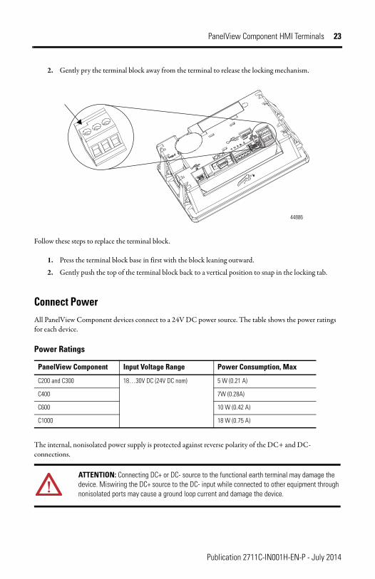
Connect PowerAll PanelView Component devices connect to a 24V DC power source. The table shows the power ratings for each device.
The internal, nonisolated power supply is protected against reverse polarity of the DC+ and DC- connections.
Power Ratings
PanelView Component Input Voltage Range Power Consumption, Max
C200 and C300 18…30V DC (24V DC nom) 5 W (0.21 A)
C400 7W (0.28A)
C600 10 W (0.42 A)
C1000 18 W (0.75 A)
ATTENTION: Connecting DC+ or DC- source to the functional earth terminal may damage the device. Miswiring the DC+ source to the DC- input while connected to other equipment through nonisolated ports may cause a ground loop current and damage the device.
44886
Publication 2711C-IN001H-EN-P - July 2014

24 PanelView Component HMI Terminals
The input power terminal block supports these wire sizes.
Follow these steps to connect power.
1. Verify that the terminal is not connected to a power source.
2. Secure the 24V DC power wires to the terminal block.
3. Secure the functional earth ground wire to the functional earth ground terminal screw on the terminal block.
WARNING: Use supply wires suitable for 30 °C (86 °F) above surrounding ambient.
WARNING: If you connect or disconnect wiring while the power is on, an electrical arc can occur. This could cause an explosion in hazardous location installations. Be sure that power is removed or the area is nonhazardous before proceeding.
Wire Specifications for Input Power Terminal Block
Wire Type Dual-wire Gauge (1)
(1) Two-wire maximum per terminal.
Single-wire Gauge
Terminal Screw Torque
Stranded or solid Cu 90 °C (194 °F) 0.33…1.31 mm2
(22…16 AWG)0.33…2.08 mm2
(22…14 AWG)0.45…0.56 Nm (4…5 lb-in.)
ATTENTION: Disconnect all power before installing or replacing components. Failure to disconnect power may result in electrical shock or damage to the terminal.
ATTENTION: Do not wire more than 2 conductors on any single terminal.
Publication 2711C-IN001H-EN-P - July 2014

PanelView Component HMI Terminals 25
4. Apply 24V DC power to the terminal.
Ground the TerminalPanelView Component devices have a functional earth terminal that you must connect to a low-impedance earth ground. The functional earth connection is on the power input terminal block. The negative power terminal is not internally connected to earth ground.
The functional earth terminal wiring requires a minimum wire gauge.
Connect DevicesUse these cables for connecting devices to PanelView Component terminals.
ATTENTION: The functional earth connection to ground is mandatory. This connection is required for noise immunity, reliability, and Electromagnetic Compliance (EMC) with the European Union (EU) EMC directive for CE-mark conformance.
Functional Earth Wire Specifications
FE Symbol Wire Type Wire Gauge Terminal Screw Torque
Stranded or solid Cu 90 °C (194 °F) 2.08…3.31 mm2
(14…12 AWG)0.45…0.56 Nm (4…5 lb-in)
Cables for PanelView Component Terminals
Cat. No. Description For Use With
2711C-CBL-UU02 USB-A host to USB-B device cable, 2 m (6.56 ft) C200, C300, C400, C600, C1000
2711P-CBL-EX04 Ethernet crossover CAT5 cable 4.3 m (14 ft) C400, C600, C1000
2711C-RCSD USB to SD adapter with secure digital (SD) card C200, C300, C400, C600, C1000
DC+
FunctionalEarth Groundto Ground Bus
DC-
44887
Publication 2711C-IN001H-EN-P - July 2014

26 PanelView Component HMI Terminals
RS-422/RS-485 PortThe RS-422/RS-485 port is a nonisolated port that supports point-to-point communications using Full-Duplex or Half-Duplex mode
• In Full-Duplex mode, both devices can transmit and receive simultaneously. The transmit and receive pair are wired individually.
• In Half-Duplex mode, only one device can transmit at a time while the other device receives. A single differential, twisted pair connects to both receive and transmit pairs (R and T and on one wire, R- and T- on the other).
The RS422/485 port has integrated 121 ohm termination between the R and R- signal pair. This value is compatible with RS422 and RS485 electrical specifications. Additional termination on the PanelView Component end of communication cables is not required.
TroubleshootingIf your terminal does not start up correctly, check for adequate power and indicator states during powerup.
Check for Adequate PowerA terminal that does not receive adequate power could cause unpredictable behavior. Verify the power requirements in the Specifications table.
1747-CP3 Serial 9-pin D-shell to 9-pin D-shell null modem cable C200, C300, C400, C600, C1000
1761-CBL-PM02 Serial 9-pin D-shell to 8-pin mini DIN cable, 2 m (6.56 ft)
C200, C300, C400, C600, C1000
2711C-CBL-AB03 RS-485 5-pin to RJ45 cable C200, C300, C600, C1000
RS-422/RS-485 Connector Pinout
Pin Signal
1 T
2 T–
3 R
4 R–
5 S (Shield)
Cables for PanelView Component Terminals
Cat. No. Description For Use With
Publication 2711C-IN001H-EN-P - July 2014

PanelView Component HMI Terminals 27
Interpret the LED Indicators at StartupThe C400, C600 and C1000 terminals have indicators on the back of the unit to isolate operating problems.
• Comm indicator for communications• Fault indicator for hardware faults
At startup, the Fault indicator is off, except for a few brief flashes, and the Comm indicator is on. If the indicators remain off, check the power cable. After a successful startup, both indicators are off and controlled by the application running on the terminal.
The table shows the indicator states if the terminal stops during startup.
Battery ReplacementThe C400, C600 and C1000 terminals contain a lithium battery that is intended to be replaced during the life of the product. The battery provides battery backup for the real-time clock. It is not used for application backup or retention.
Fault Indicator States During Startup
Fault (Red)Indicator State
Comm (Green) Indicator State
Description Recommended Action
Potentially recoverable errors
Blinking Off Last firmware download failed. Reload the firmware.
Blinking Blinking EBC boot loader firmware failed or is missing.
Reload the firmware.
Blinking On Windows CE OS firmware failed or is missing.
Reload the firmware.
Nonrecoverable or fatal errors
On Off Fatal hardware error. Replace the terminal.
On Blinking Fatal display hardware error. Replace the terminal.
WARNING: Verify that power has been removed from the terminal prior to replacing the battery. Work in a static free environment and wear a properly grounded electrostatic discharge (ESD) wristband. Be careful when touching any of the exposed electronic components to prevent damage from ESD.
Publication 2711C-IN001H-EN-P - July 2014

28 PanelView Component HMI Terminals
WARNING: To avoid the danger of explosion, only replace the battery with 2711P-RY2032 or a manufacturer’s equivalent such as the Matsushita or Duracell DL2032.
For safety information on the handling of lithium batteries, see the Guidelines for Handling Lithium Batteries, publication AG 5-4.
Do not dispose of battery in a fire or incinerator. Dispose of used batteries in accordance with local regulations.
WARNING: When you connect or disconnect the battery an electrical arc can occur. This could cause an explosion in hazardous location installations. Be sure that the area is nonhazardous before proceeding.
For Safety information on the handling of lithium batteries, including handling and disposal of leaking batteries, see Guidelines for Handling Lithium Batteries, publication AG 5-4.
At the end of its life, the used battery should be collected separately from any unsorted municipal waste and recycled.
Publication 2711C-IN001H-EN-P - July 2014

PanelView Component HMI Terminals 29
The battery is on the back of the terminals. No special tools are required to remove the battery cover and replace the battery.
Battery Cover Battery
44888This equipment is sensitive to electrostatic discharge (ESD) Follow ESD prevention guidelines when handling this equipment.
C600/C1000 Battery
Battery Cover
Battery
This equipment is sensitive to electrostatic discharge (ESD). Follow ESD prevention guidelines when handling this equipment.
C400 Battery
Publication 2711C-IN001H-EN-P - July 2014

30 PanelView Component HMI Terminals
Backlight Disposal
Specifications
IMPORTANT The backlight assembly in the PanelView C600 (2711C-T6M, 2711C-T6C only) and C1000 devices contain mercury. At the end of its life, this equipment should be collected separately from unsorted municipal waste.
PanelView Component - 2711C-F2M, 2711C-K2M, 2711C-T3M, 2711C-K3M, 2711C-T6M, 2711C-T4T, 2711C-T6C, 2711C-T6T, 2711C-T10C
Attribute Value
C200 C300 C400 C600 C1000
Display type Monochrome transflective STN passive matrix
Monochrome transflective FSTN passive matrix
Color transmissive TFT active matrix LCD
Monochrome transmissive FSTN passive matrix or Color transmissive CSTN passive matrix orColor transmissive TFT active matrix LCD
Color transmissive TFT active matrix LCD
Display size 2 in. 3 in. 4 in. 5.7 in. 10.4 in.
Display area 49 x 14 mm (1.93 x 0.55 in.)
67 x 33 mm (2.64 x 1.30 in.)
95.04 x 53.86 mm(3.74 X 2.12 in.)
115 x 86 mm (4.53 x 3.39 in.)
211 x 158 mm (8.31 x 6.22 in.)
Resolution (pixels)
122 x 32 128 x 64 480 X 272 320 x 240 640 x 480
Backlight 50,000 hours life, min., backlight not replaceable
40,000 hours life, min., backlight not replaceable
50,000 hours life, min., backlight not replaceable
Yellow/Green LED indicator
White LED indicator For 2711C-T6C and 2711C-T10C – CCFLFor 2711C-T6T – 40,000 hours life, min.,White LED backlight, not replaceable
Operator input Function keys or combination function keys and numeric keypad
Analog touch or combination function keys and numeric keypad
Analog touch and function keys
Analog touch
Memory card USB port USB port and Secure digital (SD) card
Programming port
USB device port
Battery life, min.
5 years at 25 °C (77 °F)
Real-time clock No battery backup Battery backup
Input voltage range
18…30V DC (24V DC nom)
Publication 2711C-IN001H-EN-P - July 2014
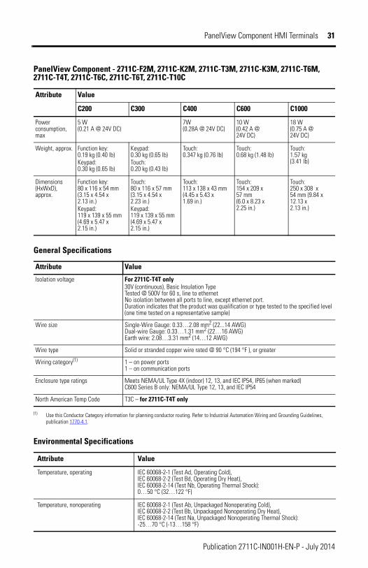
PanelView Component HMI Terminals 31
Power consumption, max
5 W(0.21 A @ 24V DC)
7W (0.28A @ 24V DC)
10 W(0.42 A @ 24V DC)
18 W(0.75 A @ 24V DC)
Weight, approx. Function key:0.19 kg (0.40 lb)Keypad:0.30 kg (0.65 lb)
Keypad:0.30 kg (0.65 lb)Touch:0.20 kg (0.43 lb)
Touch:0.347 kg (0.76 lb)
Touch:0.68 kg (1.48 lb)
Touch:1.57 kg (3.41 lb)
Dimensions (HxWxD), approx.
Function key:80 x 116 x 54 mm (3.15 x 4.54 x 2.13 in.)Keypad:119 x 139 x 55 mm (4.69 x 5.47 x 2.15 in.)
Touch:80 x 116 x 57 mm (3.15 x 4.54 x 2.23 in.)Keypad:119 x 139 x 55 mm (4.69 x 5.47 x 2.15 in.)
Touch:113 x 138 x 43 mm(4.45 x 5.43 x 1.69 in.)
Touch:154 x 209 x 57 mm (6.0 x 8.23 x 2.25 in.)
Touch:250 x 308 x 54 mm (9.84 x 12.13 x 2.13 in.)
General Specifications
Attribute Value
Isolation voltage For 2711C-T4T only30V (continuous), Basic Insulation TypeTested @ 500V for 60 s, line to ethernet No isolation between all ports to line, except ethernet port.Duration indicates that the product was qualification or type tested to the specified level (one time tested on a representative sample)
Wire size Single-Wire Gauge: 0.33…2.08 mm2 (22...14 AWG)Dual-wire Gauge: 0.33…1.31 mm2 (22…16 AWG)Earth wire: 2.08…3.31 mm2 (14…12 AWG)
Wire type Solid or stranded copper wire rated @ 90 °C (194 °F ), or greater
Wiring category(1) 1 – on power ports1 – on communication ports
Enclosure type ratings Meets NEMA/UL Type 4X (indoor) 12, 13, and IEC IP54, IP65 (when marked)C600 Series B only: NEMA/UL Type 12, 13, and IEC IP54
North American Temp Code T3C – for 2711C-T4T only
(1) Use this Conductor Category information for planning conductor routing. Refer to Industrial Automation Wiring and Grounding Guidelines, publication 1770-4.1.
Environmental Specifications
Attribute Value
Temperature, operating IEC 60068-2-1 (Test Ad, Operating Cold),IEC 60068-2-2 (Test Bd, Operating Dry Heat),IEC 60068-2-14 (Test Nb, Operating Thermal Shock):0…50 °C (32…122 °F)
Temperature, nonoperating IEC 60068-2-1 (Test Ab, Unpackaged Nonoperating Cold),IEC 60068-2-2 (Test Bb, Unpackaged Nonoperating Dry Heat),IEC 60068-2-14 (Test Na, Unpackaged Nonoperating Thermal Shock):-25…70 °C (-13…158 °F)
PanelView Component - 2711C-F2M, 2711C-K2M, 2711C-T3M, 2711C-K3M, 2711C-T6M, 2711C-T4T, 2711C-T6C, 2711C-T6T, 2711C-T10C
Attribute Value
C200 C300 C400 C600 C1000
Publication 2711C-IN001H-EN-P - July 2014

32 PanelView Component HMI Terminals
Temperature, surrounding, max 50 °C (122 °F)
Heat dissipationC200 and C300C400C600C1000
16 BTU/hr24 BTU/hr32 BTU/hr58 BTU/hr
Relative humidity IEC 60068-2-30 (Test Db, Unpackaged Damp Heat):5…95% noncondensing
Vibration IEC 60068-2-6 (Test Fc, Operating):2 g @ 10…500 Hz
Shock, operating IEC 60068-2-27 (Test Ea, Unpackaged Shock):15 g @ 11 ms
Shock, nonoperating IEC 60068-2-27 (Test Ea, Unpackaged Shock):30 g
Emissions CISPR 11:Group 1, Class A
ESD Immunity IEC 61000-4-2:4 kV contact discharges8 kV air discharges
Radiated RF Immunity IEC 61000-4-3:10V/m with 1 kHz sine-wave 80% AM from 80…2000 MHz3V/m with 1 kHz sine-wave 80% AM from 1400…2000 MHz1V/m with 1 kHz sine-wave 80% AM from 2000…2700 MHz
EFT/B Immunity IEC 61000-4-4:±2 kV @ 5 kHz on power ports±1 kV @ 5 kHz on communication ports
Surge Transient Immunity IEC 61000-4-5:±500V line-line(DM) and ±1 kV line-earth(CM) on DC power ports±1 kV line-earth(CM) on communication ports
Conducted RF Immunity IEC 61000-4-6:10V rms with 1 kHz sine-wave 80% AM from 150 kHz…80 MHz
Certifications
Certifications (when product is marked) (1)
Value
c-UL-us UL Listed Industrial Control Equipment, certified for US and Canada. See UL File E113724.
UL Listed for Class I, Division 2 Group A,B,C,D Hazardous Locations, certified for U.S. and Canada. See UL File E10314. - For 2711C-T4T only
CE European Union 2004/108/EC EMC Directive, compliant with:EN 61000-6-2; Industrial ImmunityEN 61000-6-4; Industrial Emissions
Environmental Specifications
Attribute Value
Publication 2711C-IN001H-EN-P - July 2014

PanelView Component HMI Terminals 33
Additional ResourcesYou can view or download publications at http://www.literature.rockwellautomation.com. To order paper copies of technical documentation, contact your local Rockwell Automation distributor or sales representative.
EAC Russian Customs Union TR CU 020/2011 EMC Technical Regulation
RCM Australian Radiocommunications Act, compliant with:AS/NZS CISPR 11; Industrial Emissions
KC Korean Registration of Broadcasting and Communications Equipment, compliant with:Article 58-2 of Radio Waves Act, Clause 3
(1) See the Product Certification link at http;//www.ab.com for Declarations of Conformity, Certificates, and other certification details.
Certifications
Publication 2711C-IN001H-EN-P - July 2014

34 PanelView Component HMI Terminals
Notes:
Publication 2711C-IN001H-EN-P - July 2014

PanelView Component HMI Terminals 35
Notes:
Publication 2711C-IN001H-EN-P - July 2014

Rockwell Automation Support
Publication 2711C-IN001H-EN-P - July 2014 PN-265995Supersedes Publication 2711C-IN001G-EN-P - December 2011 Copyright © 2014 Rockwell Automation, Inc. All rights reserved. Printed in Singapore.
Rockwell Automation provides technical information on the Web to assist you in using its products. At http://www.rockwellautomation.com/support/, you can find technical manuals, a knowledge base of FAQs, technical and application notes, sample code and links to software service packs, and a MySupport feature that you can customize to make the best use of these tools.
For an additional level of technical phone support for installation, configuration and troubleshooting, we offer TechConnect support programs. For more information, contact your local distributor or Rockwell Automation representative, or visit http://www.rockwellautomation.com/support/.
Installation AssistanceIf you experience a problem within the first 24 hours of installation, please review the information that's contained in this manual. You can also contact a special Customer Support number for initial help in getting your product up and running.
New Product Satisfaction ReturnRockwell Automation tests all of its products to ensure that they are fully operational when shipped from the manufacturing facility. However, if your product is not functioning and needs to be returned, follow these procedures.
Documentation FeedbackYour comments will help us serve your documentation needs better. If you have any suggestions on how to improve this document, complete this form, publication RA-DU002, available at http://www.rockwellautomation.com/literature/.
United States or Canada 1.440.646.3434
Outside United States or Canada Use the Worldwide Locator at http://www.rockwellautomation.com/support/americas/phone_en.html, or contact your local Rockwell Automation representative.
United States Contact your distributor. You must provide a Customer Support case number (call the phone number above to obtain one) to your distributor to complete the return process.
Outside United States Please contact your local Rockwell Automation representative for the return procedure.