PanelView 1200 Operator Terminals - UNIS Group · PanelView 1200 Operator Terminals (Catalog...
103
PanelViewt1200 Operator Terminals (Catalog Numbers 2711-KA1, KC1, TA1, TC1, TA4, TC4) User Manual
-
Upload
nguyenphuc -
Category
Documents
-
view
220 -
download
0
Transcript of PanelView 1200 Operator Terminals - UNIS Group · PanelView 1200 Operator Terminals (Catalog...

PanelView�1200 Operator Terminals(Catalog Numbers 2711-KA1, KC1, TA1, TC1, TA4, TC4)
User Manual
Solid-state equipment has operational characteristics differing from thoseof electromechanical equipment. “Safety Guidelines for the Application,Installation and Maintenance of Solid State Controls” (PublicationSGI–1.1) describes some important differences between solid-stateequipment and hard-wired electromechanical devices. Because of thisdifference, and also because of the wide variety of uses for solid-stateequipment, all persons responsible for applying this equipment must satisfythemselves that each intended application of this equipment is acceptable.
In no event will the Allen-Bradley Company be responsible or liable forindirect or consequential damages resulting from the use or application ofthis equipment.
The examples and diagrams in this manual are included solely forillustrative purposes. Because of the many variables and requirementsassociated with any particular installation, the Allen-Bradley Companycannot assume responsibility or liability for actual use based on theexamples and diagrams.
No patent liability is assumed by Allen-Bradley Company with respect touse of information, circuits, equipment, or software described in thismanual.
Reproduction of the contents of this manual, in whole or in part, withoutwritten permission of the Allen-Bradley Company is prohibited.
Throughout this manual we use notes to make you aware of safetyconsiderations.
Attention Identifies information about practices or circumstancesthat can lead to personal injury or death, property damage, oreconomic loss.
Attentions help you:
identify a hazard avoid the hazard recognize the consequences
Important Identifies information that is especially important for successfulapplication and understanding of the product.PanelBuilder, PanelView, Data Highway Plus, DH+, SLC and SLC 500 are trademarks, and PLC, PLC-2, and PLC-3 are registeredtrademarks of Allen-Bradley Company, Inc.
Intel is a trademark of Intel Corp.
IBM, PC, AT, XT, PS/2 and PC DOS are registered trademarks of International Business Machines Corporation
Epson is a registered trademark of Seiko Epson Corporation
Microsoft Windows is a trademark, and Microsoft, MS, and MS-DOS are registered trademarks of Microsoft Corporation
Important User Information
Preface P�1. . . . . . . . . . . . . . . . . . . . . . . . . . . . . . . . . . . . . . .
Manual Overview P�1. . . . . . . . . . . . . . . . . . . . . . . . . . . . . . . . . . . .
Intended Audience P�1. . . . . . . . . . . . . . . . . . . . . . . . . . . . . . . . . . .
Glossary of Terms P�1. . . . . . . . . . . . . . . . . . . . . . . . . . . . . . . . . . .
Related Publications P�3. . . . . . . . . . . . . . . . . . . . . . . . . . . . . . . . . .
After�Sales Support P�4. . . . . . . . . . . . . . . . . . . . . . . . . . . . . . . . . .
Introduction to PanelView 1200 Operator Terminals 1�1. . . . . .
The PanelView 1200 Terminal Family 1�1. . . . . . . . . . . . . . . . . . . . . .
Wide Range of Applications 1�3. . . . . . . . . . . . . . . . . . . . . . . . . .
PanelView 1200 Features 1�3. . . . . . . . . . . . . . . . . . . . . . . . . . . . . .
Cost Optimized for OEM Applications 1�3. . . . . . . . . . . . . . . . . . . .
Rugged, High Quality Design 1�3. . . . . . . . . . . . . . . . . . . . . . . . .
Panel or 19" Rack Mounting 1�3. . . . . . . . . . . . . . . . . . . . . . . . . .
12" Monochrome or Color Display 1�4. . . . . . . . . . . . . . . . . . . . . .
Direct Connection to any Allen�Bradley PLC Remote I/O Link 1�4. . .
Direct or Data Highway Plus and Remote I/O Downloading 1�4. . . .
Factory Installed Battery Provides Extended Back�up 1�4. . . . . . . .
User�Definable Keys 1�5. . . . . . . . . . . . . . . . . . . . . . . . . . . . . . .
Custom Keypad Legend Inserts 1�5. . . . . . . . . . . . . . . . . . . . . . . .
Touch Screen Terminal for Simplicity and Space Saving 1�5. . . . . .
Message and Alarm Handling Utilities 1�5. . . . . . . . . . . . . . . . . . .
Built�in Clock 1�6. . . . . . . . . . . . . . . . . . . . . . . . . . . . . . . . . . . . .
Audio and Visual Feedback 1�6. . . . . . . . . . . . . . . . . . . . . . . . . . .
Alarm Relay 1�6. . . . . . . . . . . . . . . . . . . . . . . . . . . . . . . . . . . . . .
RS�232 Port 1�6. . . . . . . . . . . . . . . . . . . . . . . . . . . . . . . . . . . . .
PanelView 1200 Terminal Diagnostics 1�7. . . . . . . . . . . . . . . . . . .
Options and Accessories 1�7. . . . . . . . . . . . . . . . . . . . . . . . . . . . . .
Upload/Download Cable 1�7. . . . . . . . . . . . . . . . . . . . . . . . . . . . .
Optional Remote Keyswitch & RS�232 Port Assembly 1�7. . . . . . . .
Optional EEPROM or EPROM for Back�up or Additional Application Memory 1�7. . . . . . . . . . . . . . . . . . . . . . . . . . . . . .
Functional Variations Among Terminal Types 1�8. . . . . . . . . . . . . .
Keypad Terminals 1�8. . . . . . . . . . . . . . . . . . . . . . . . . . . . . . . . . . .
Function Keys 1�9. . . . . . . . . . . . . . . . . . . . . . . . . . . . . . . . . . . .
Numeric Keypad 1�9. . . . . . . . . . . . . . . . . . . . . . . . . . . . . . . . . .
Special Keys 1�10. . . . . . . . . . . . . . . . . . . . . . . . . . . . . . . . . . . . .
Touch Screen Terminals 1�10. . . . . . . . . . . . . . . . . . . . . . . . . . . . . . .
Objects, Windows, and PLC Control Options 1�11. . . . . . . . . . . . . . . .
Objects Common to All PanelView 1200 Terminals 1�13. . . . . . . . . . . .
Objects for the Keypad Terminal 1�15. . . . . . . . . . . . . . . . . . . . . . . . .
Objects for the Touch Screen Terminal 1�16. . . . . . . . . . . . . . . . . . . . .
Table of Contents
Table of Contentsii
Information and Alarm Windows 1�16. . . . . . . . . . . . . . . . . . . . . . . . .
Summary of PLC Controlled Options 1�17. . . . . . . . . . . . . . . . . . . . . .
Applicable Programmable Controllers and Connections 1�17. . . . . . . . .
PLC�5/11, 5/15, 5/20, 5/25, 5/30, 5/40, 5/60 and 5/250 Processors 1�18
PLC�5/10 Processor 1�18. . . . . . . . . . . . . . . . . . . . . . . . . . . . . . . .
PLC�3 and PLC�3/10 Processors 1�18. . . . . . . . . . . . . . . . . . . . . . .
PLC�2 Family Processors via 1771�SN or 1772�SD2 1�18. . . . . . . . .
SLC�5/02 via 1747�SN 1�19. . . . . . . . . . . . . . . . . . . . . . . . . . . . . .
1771�SN I/O Subscanner Module 1�19. . . . . . . . . . . . . . . . . . . . . .
6008�SI IBM PC I/O Scanner 1�19. . . . . . . . . . . . . . . . . . . . . . . . . .
6008�SV VME I/O Scanner 1�19. . . . . . . . . . . . . . . . . . . . . . . . . . .
6008�SQ DEC Q�BUS I/O Scanner 1�19. . . . . . . . . . . . . . . . . . . . .
PanelView 1200 Terminal Functions 2�1. . . . . . . . . . . . . . . . . .
Contrast, Brightness and the Mode Select Keyswitch 2�1. . . . . . . . . .
Fault Conditions 2�2. . . . . . . . . . . . . . . . . . . . . . . . . . . . . . . . . . . . .
Major Faults 2�2. . . . . . . . . . . . . . . . . . . . . . . . . . . . . . . . . . . . .
Minor Faults 2�2. . . . . . . . . . . . . . . . . . . . . . . . . . . . . . . . . . . . .
Power�Up Functions 2�3. . . . . . . . . . . . . . . . . . . . . . . . . . . . . . . . . .
Checksum and Read/Write Memory Tests 2�3. . . . . . . . . . . . . . . .
Battery Failure Test 2�4. . . . . . . . . . . . . . . . . . . . . . . . . . . . . . . .
Communication Test 2�5. . . . . . . . . . . . . . . . . . . . . . . . . . . . . . . .
Watchdog Test 2�5. . . . . . . . . . . . . . . . . . . . . . . . . . . . . . . . . . . .
Starting Up the Terminal in Configuration Mode 2�5. . . . . . . . . . . . . . .
The Configuration Mode Menu 2�6. . . . . . . . . . . . . . . . . . . . . . . . . .
Upload/Download 2�6. . . . . . . . . . . . . . . . . . . . . . . . . . . . . . . . . .
Serial Port 2�7. . . . . . . . . . . . . . . . . . . . . . . . . . . . . . . . . . . . . . .
Rack Assignments 2�8. . . . . . . . . . . . . . . . . . . . . . . . . . . . . . . . .
Access Codes 2�9. . . . . . . . . . . . . . . . . . . . . . . . . . . . . . . . . . . .
Audio Response 2�10. . . . . . . . . . . . . . . . . . . . . . . . . . . . . . . . . .
Alarm Relay 2�10. . . . . . . . . . . . . . . . . . . . . . . . . . . . . . . . . . . . . .
Preset Operations 2�10. . . . . . . . . . . . . . . . . . . . . . . . . . . . . . . . .
Time and Date 2�12. . . . . . . . . . . . . . . . . . . . . . . . . . . . . . . . . . . .
Screen Saver 2�12. . . . . . . . . . . . . . . . . . . . . . . . . . . . . . . . . . . .
Screen Alignment 2�13. . . . . . . . . . . . . . . . . . . . . . . . . . . . . . . . . .
Stuck Button/Cell Timeout 2�14. . . . . . . . . . . . . . . . . . . . . . . . . . . .
False Depression Test (Touch Screen Only) 2�14. . . . . . . . . . . . . . .
User EPROM/EEPROM Power�Up Test 2�15. . . . . . . . . . . . . . . . . .
Pass�Through Download Options 2�17. . . . . . . . . . . . . . . . . . . . . .
Unit Tests 2�21. . . . . . . . . . . . . . . . . . . . . . . . . . . . . . . . . . . . . . .
Run Mode Functions 2�23. . . . . . . . . . . . . . . . . . . . . . . . . . . . . . . . .
On�line Diagnostic Testing 2�24. . . . . . . . . . . . . . . . . . . . . . . . . . . . .
PLC Communication Timeout 2�24. . . . . . . . . . . . . . . . . . . . . . . . .
Invalid Screen Request 2�24. . . . . . . . . . . . . . . . . . . . . . . . . . . . . .
Application Data Checksum 2�24. . . . . . . . . . . . . . . . . . . . . . . . . .

Table of Contents iii
Battery Failure 2�24. . . . . . . . . . . . . . . . . . . . . . . . . . . . . . . . . . . .
PanelView 1200 Terminal Printing 2�24. . . . . . . . . . . . . . . . . . . . . . . .
Print Priorities 2�25. . . . . . . . . . . . . . . . . . . . . . . . . . . . . . . . . . . .
Page Formatting 2�25. . . . . . . . . . . . . . . . . . . . . . . . . . . . . . . . . .
Non�Printable Characters 2�26. . . . . . . . . . . . . . . . . . . . . . . . . . . .
Printer Errors 2�26. . . . . . . . . . . . . . . . . . . . . . . . . . . . . . . . . . . . .
Installing Your PanelView 1200 Terminal 3�1. . . . . . . . . . . . . .
The PanelView 1200 Terminal 3�2. . . . . . . . . . . . . . . . . . . . . . . . . . .
The RS�232 Port 3�2. . . . . . . . . . . . . . . . . . . . . . . . . . . . . . . . . .
The Alarm Relay Connector 3�3. . . . . . . . . . . . . . . . . . . . . . . . . .
The Remote I/O Connector 3�4. . . . . . . . . . . . . . . . . . . . . . . . . . .
The AC Power Connector 3�4. . . . . . . . . . . . . . . . . . . . . . . . . . . .
Installing a User PROM 3�5. . . . . . . . . . . . . . . . . . . . . . . . . . . . . . .
PanelView 1200 Terminal Dimensions 3�9. . . . . . . . . . . . . . . . . . . . .
Installation Notes 3�11. . . . . . . . . . . . . . . . . . . . . . . . . . . . . . . . . .
PanelView 1200 Terminal Cutouts 3�11. . . . . . . . . . . . . . . . . . . . . . . .
Keypad Terminals (2711�KA1, 2711�KC1) 3�12. . . . . . . . . . . . . . . . .
Touch Screen Terminals (2711�TA1, TC1) 3�13. . . . . . . . . . . . . . . .
Touch Screen Terminals (2711�TA4, TC4) 3�14. . . . . . . . . . . . . . . .
Optional Clip or Stud Rack Mount Kits 3�15. . . . . . . . . . . . . . . . . . . . .
Remote Keyswitch Assembly Dimensions 3�16. . . . . . . . . . . . . . . . . .
Upload/Download Cable 3�16. . . . . . . . . . . . . . . . . . . . . . . . . . . . . . .
Verifying the PanelView 1200 Terminal Operation 4�1. . . . . . .
Testing the PanelView 1200 Terminal 4�1. . . . . . . . . . . . . . . . . . . . . .
Downloading the Application File 4�2. . . . . . . . . . . . . . . . . . . . . . . . .
Matching Communications Settings 4�2. . . . . . . . . . . . . . . . . . . . .
Downloading the Application 4�2. . . . . . . . . . . . . . . . . . . . . . . . . .
Running the Application File 4�3. . . . . . . . . . . . . . . . . . . . . . . . . . . .
Connecting the PLC Controller 4�3. . . . . . . . . . . . . . . . . . . . . . . . . .
Testing Retentive Objects 4�4. . . . . . . . . . . . . . . . . . . . . . . . . . . .
Testing the Whole System 4�4. . . . . . . . . . . . . . . . . . . . . . . . . . . . . .
Maintaining Your PanelView 1200 Terminal 5�1. . . . . . . . . . . .
Cleaning 5�1. . . . . . . . . . . . . . . . . . . . . . . . . . . . . . . . . . . . . . . . . .
Changing the Filter on Color Units 5�2. . . . . . . . . . . . . . . . . . . . . . . .
Screen Saver 5�2. . . . . . . . . . . . . . . . . . . . . . . . . . . . . . . . . . . . . .
Degauss 5�2. . . . . . . . . . . . . . . . . . . . . . . . . . . . . . . . . . . . . . . . . .
Strong Magnetic Fields 5�3. . . . . . . . . . . . . . . . . . . . . . . . . . . . . . . .

Table of Contentsiv
Specifications A�1. . . . . . . . . . . . . . . . . . . . . . . . . . . . . . . . . .
Design Certifications, Standards and Compliances A�1. . . . . . . . . . . .
Design Standards Complied With A�1. . . . . . . . . . . . . . . . . . . . . .
Terminal Weights A�2. . . . . . . . . . . . . . . . . . . . . . . . . . . . . . . . . . . .
Keypad Terminals A�2. . . . . . . . . . . . . . . . . . . . . . . . . . . . . . . . .
Front Panel Design A�2. . . . . . . . . . . . . . . . . . . . . . . . . . . . . . . . . .
Touch Screen Terminals A�2. . . . . . . . . . . . . . . . . . . . . . . . . . . . .
CRT Display A�3. . . . . . . . . . . . . . . . . . . . . . . . . . . . . . . . . . . . . . .
Color Unit Display Attributes A�3. . . . . . . . . . . . . . . . . . . . . . . . . .
Monochrome Unit Display Attributes A�4. . . . . . . . . . . . . . . . . . . .
PLC Remote I/O Communications A�4. . . . . . . . . . . . . . . . . . . . . . . .
Serial Communications Port A�5. . . . . . . . . . . . . . . . . . . . . . . . . . . .
AC Power A�5. . . . . . . . . . . . . . . . . . . . . . . . . . . . . . . . . . . . . . . . .
Fuses A�6. . . . . . . . . . . . . . . . . . . . . . . . . . . . . . . . . . . . . . . . . . . .
Character Set A�6. . . . . . . . . . . . . . . . . . . . . . . . . . . . . . . . . . . . . .
User Memory A�6. . . . . . . . . . . . . . . . . . . . . . . . . . . . . . . . . . . . . . .
Alarm Relay A�6. . . . . . . . . . . . . . . . . . . . . . . . . . . . . . . . . . . . . . . .
Batteries A�7. . . . . . . . . . . . . . . . . . . . . . . . . . . . . . . . . . . . . . . . . .
Time and Date Clock A�7. . . . . . . . . . . . . . . . . . . . . . . . . . . . . . . . .
Ambient Operating Temperature Limits A�8. . . . . . . . . . . . . . . . . . .
Temperature, Humidity, and High Altitude A�8. . . . . . . . . . . . . . . . . . .
Storage Temperature Limits A�8. . . . . . . . . . . . . . . . . . . . . . . . . .
Humidity A�8. . . . . . . . . . . . . . . . . . . . . . . . . . . . . . . . . . . . . . . .
Maximum Altitude A�8. . . . . . . . . . . . . . . . . . . . . . . . . . . . . . . . . .
Monochrome Terminals A�8. . . . . . . . . . . . . . . . . . . . . . . . . . . . .
Heat Generation A�8. . . . . . . . . . . . . . . . . . . . . . . . . . . . . . . . . . . .
Color Terminals A�8. . . . . . . . . . . . . . . . . . . . . . . . . . . . . . . . . . .
Shock Amplitudes A�9. . . . . . . . . . . . . . . . . . . . . . . . . . . . . . . . .
Shock and Vibration A�9. . . . . . . . . . . . . . . . . . . . . . . . . . . . . . . . . .
Vibration Amplitudes for Operating Units A�9. . . . . . . . . . . . . . . . .
Vibration Amplitudes for Non�Operating Units A�9. . . . . . . . . . . . . .
Troubleshooting B�1. . . . . . . . . . . . . . . . . . . . . . . . . . . . . . . .
Verifying Configuration Settings B�1. . . . . . . . . . . . . . . . . . . . . . . . . .
PanelView 1200 Major Fault Error Messages B�1. . . . . . . . . . . . . . . .
PanelView 1200 Minor Fault Error Messages B�2. . . . . . . . . . . . . . . .
PLC Communication Problems B�3. . . . . . . . . . . . . . . . . . . . . . . . . .
Pass�Through Upload/Download Problems B�4. . . . . . . . . . . . . . . . .
PLC Controllers Required for Pass�Through B�5. . . . . . . . . . . . . . .
Common Error Messages for Manual Address Source Configuration B�6. . . . . . . . . . . . . . . . . . . . . . . . . . . .
Common Pass�Through Error Codes B�6. . . . . . . . . . . . . . . . . . . .
PanelBuilder Problems B�7. . . . . . . . . . . . . . . . . . . . . . . . . . . . . . . .

Preface
P-1
Preface
This manual describes the features and specifications of PanelView 1200terminals. PanelView 1200 terminals are available as keypad or touchscreen terminals, with color or monochrome display.
Note The term “PanelView 1200” is the new name for PanelViewterminals. It refers to all 12-inch CRT PanelView terminals, from Series Aupwards.
The manual provides information and examples for:
installing and maintaining a PanelView 1200 terminal
operating a PanelView 1200 terminal
connecting a PanelView 1200 terminal to an Allen-BradleyProgrammable Logic Controller (PLC�)
troubleshooting a PanelView 1200 terminal
This manual is written to help you install and maintain PanelView 1200terminals.
The following terms are used throughout this manual.
Application File: A PanelView 1200 terminal application file contains aseries of screens and configurations which, when interpreted and executedby PanelView 1200, replace the functions of a control panel of buttons,switches and indicators. The screens are created on a developmentcomputer running PanelBuilder Development Software orPanelBuilder 1200 Configuration Software for Windows, and then savedin an application file on the development computer’s disk. The applicationfile is then downloaded to a PanelView 1200 terminal where it stays inbattery-backed RAM.
Battery-Backed RAM: Application files are stored in the PanelView 1200terminal’s random access memory (RAM). The RAM is backed by aninternal battery so that the application file and the status of the retentiveobjects are maintained even when AC power is switched off.
Manual Overview
Intended Audience
Glossary of Terms

Preface
P-2
Hex Files: Application files which have been converted into Intel Hexformat for transfer to user PROMs.
Object: An object is an individual component of a PanelView 1200 screen.Each object takes the function of a button, switch or indicator on a controlpanel. The objects can be dynamic—they can change color or value andcan display information. Each object is defined by the developer of thePanelView 1200 screen. Examples of objects include Push Buttons,Selectors, Bar Graphs, Numeric Displays, etc.
PanelBuilder Software: The program runs on the development computerto develop application files for PanelView 1200 terminals. There are twotypes of PanelBuilder software: PanelBuilder 1200 ConfigurationSoftware for Windows and PanelBuilder Development Software for DOS.
PanelView 1200 Terminal: A type of Allen-Bradley terminal with a touchscreen or rugged keypad, designed for easy operator interaction with aPLC system over the Remote I/O link.
Retentive: An object is described as retentive when it “retains” its PLCvalue in the PanelView 1200 terminal after a screen change, an operator’sobject action, and even after the terminal’s power cycle. For example,when a maintained push button is pressed, the corresponding PLC input isset to 1 and will not change until the button is pressed a second time.Retentive objects always display their current states or values.
Screen: A display containing objects (such as push buttons or bar graphs)which can monitor and control a PLC system. Screens are created witheither type of the PanelBuilder software.
SRAM: Static Random Access Memory. A type of memory that canmaintain its contents through the use of a battery. It does not requirecontinuous refreshing to maintain its contents.
System Memory: The read-only memory that contains the operatingfirmware for the PanelView 1200 terminal.
Upload/Download: Downloading is the process of transferring anapplication file from a development computer running either type of thePanelBuilder software, to a PanelView 1200 terminal. Uploading is theprocess of transferring an application file from the terminal back to thedevelopment computer.
User PROM: The read-only memory chip that can be used to contain aback-up copy of an application file, or to increase the memory available forthe application file from 64K to 128K. The chip can be either an EPROMor an EEPROM.

Preface
P-3
There are two types of user PROM chips that can be used in PanelView1200 terminal: EPROMs and EEPROMs. EPROMs are ElectricallyProgrammable Read Only Memory chips. EEPROMs are ElectricallyErasable Programmable Read Only Memory chips.
The user PROMs store application files in memory that is protected frompower failure and failure of the internal battery. A PROM burner isrequired to copy application files into a user EPROM.
If your system includes a user EEPROM, application files downloadedthrough the Upload/Download cable will be stored in both battery-backedRAM and in the EEPROM. No PROM burner is required.
Window: An area on the screen containing information. These windowsare triggered by the PLC controller and overlay any screen that isdisplayed.
The following related publications provide additional information onprogrammable controllers and I/O scanners.
Publication Pub. No.
1772�SD/SD2 Remote I/O Scanner/Distribution Panel 1772�2.18
1775�S4A I/O Scanner-Programmer Interface Module User's Manual 1775�6.5.1
1775�S5, 1775�SR5 I/O Scanner�Communication Adapter Module User'sManual
1775�6.5.5
5150�RS PI Start�up and Integration Manual 5000�6.5.1
6008�SI IBM� PC� I/O Scanner User's Manual 6008�6.5.3
6008�SV VME I/O Scanner User's Manual 6008�6.5.2
6008�SQ Q�Bus I/O Scanner Utility Software User's Manual 6008�6.4.1
1771�SN Sub I/O Scanner Module Data Sheet 1771�2.91
1747�SN RIO Scanner User's Manual 1747�NM005
Publication Pub. No.
1772�LP2 PLC�2/20 Programming and Operations Manual 1772�6.8.1
1772�LP3 PLC�2/30 Controller Programming and Operations Manual 1772�6.8.3
PLC�3 Family Controller Programming Reference Manual 1775�6.4.1
PLC�5 Family Programmable Controllers Hardware Installation Manual 1785�6.6.1
PLC�5 Programming Software 6200�6.4.7
5250�LP1, LP2 PLC�5/250 Programming Manual 5000�6.4.8
SLC� 500 Family of Programmable Controllers Advanced ProgrammingSoftware User's Manual
1747�NM002
Related Publications

Preface
P-4
To identify the manuals referring to these programmable controllers,consult the Publications Index, Publication SD499, available fromAllen-Bradley.
If you need help with your PanelView 1200 terminal, contact:
Allen-Bradley Global Technical Support6680 Beta DriveMayfield Village, Ohio 44143
Inside USA and Canada: 1-800-289-2279
Outside USA and Canada, contact your local Allen-Bradley office or callUSA (216) 646-6800.
Your terminal’s catalog number, series, revision letter and firmwarerevision are shown on the label on the back of the terminal. Please havethis information ready when you call for technical support.
Please register your PanelView 1200 terminal by mailing the registrationcard to the address above, or by FAXing the card to (216) 646-6770.
After�Sales Support
Chapter
1
1-1
Introduction to PanelView 1200 OperatorTerminals
This chapter provides an overview of the PanelView 1200 terminals. Itdescribes:
the types and features of PanelView 1200 terminals
the available options and accessories
the supported Allen-Bradley programmable controllers and remote I/Oscanners
PanelView 1200 terminals provide a fast, easy, flexible and low costoperator interface for a PLC system. They are ideal replacements fortraditional control panels.
PanelView 1200 terminals are pre-assembled and ready to install in acontrol panel cut-out or 19” rack. They connect directly to anyAllen-Bradley remote I/O link.
An Allen-Bradley, IBM or compatible computer (the developmentcomputer) is used to create PanelView 1200 terminal screens andfunctions. See the PanelBuilder Development Software User Manual forinformation on PanelBuilder Development Software for DOS. See thePanelBuilder 1200 Configuration Software for Windows User Manual formore information on PanelBuilder 1200 Configuration Software forWindows.
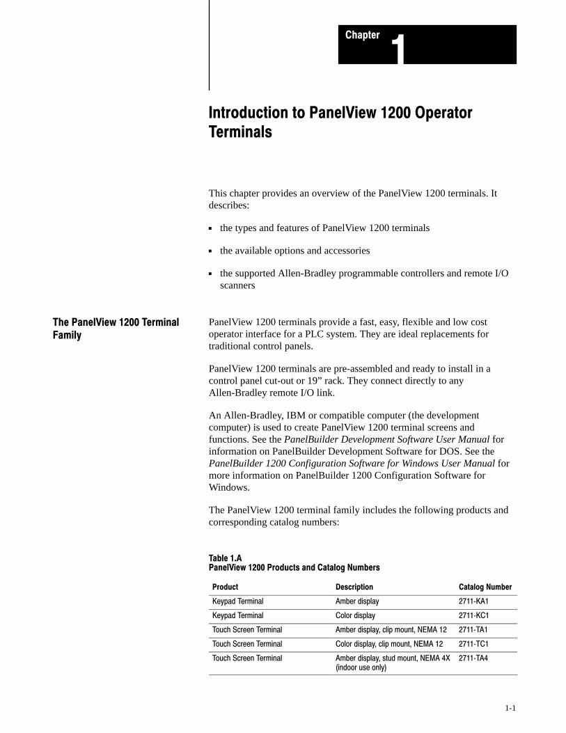
The PanelView 1200 terminal family includes the following products andcorresponding catalog numbers:
Table 1.APanelView 1200 Products and Catalog Numbers
ÁÁÁÁÁÁÁÁÁÁÁÁÁÁÁÁÁÁÁÁ
ProductÁÁÁÁÁÁÁÁÁÁÁÁÁÁÁÁÁÁ
DescriptionÁÁÁÁÁÁÁÁÁÁCatalog Number
ÁÁÁÁÁÁÁÁÁÁÁÁÁÁÁÁÁÁÁÁ
Keypad TerminalÁÁÁÁÁÁÁÁÁÁÁÁÁÁÁÁÁÁ
Amber displayÁÁÁÁÁÁÁÁÁÁ2711�KA1
ÁÁÁÁÁÁÁÁÁÁÁÁÁÁÁÁÁÁÁÁ
Keypad TerminalÁÁÁÁÁÁÁÁÁÁÁÁÁÁÁÁÁÁ
Color displayÁÁÁÁÁÁÁÁÁÁ2711�KC1
ÁÁÁÁÁÁÁÁÁÁÁÁÁÁÁÁÁÁÁÁ
Touch Screen TerminalÁÁÁÁÁÁÁÁÁÁÁÁÁÁÁÁÁÁ
Amber display, clip mount, NEMA 12ÁÁÁÁÁÁÁÁÁÁ2711�TA1
ÁÁÁÁÁÁÁÁÁÁÁÁÁÁÁÁÁÁÁÁ
Touch Screen TerminalÁÁÁÁÁÁÁÁÁÁÁÁÁÁÁÁÁÁ
Color display, clip mount, NEMA 12ÁÁÁÁÁÁÁÁÁÁ2711�TC1
ÁÁÁÁÁÁÁÁÁÁÁÁÁÁÁÁÁÁÁÁÁÁÁÁÁÁÁÁÁÁ
Touch Screen TerminalÁÁÁÁÁÁÁÁÁÁÁÁÁÁÁÁÁÁÁÁÁÁÁÁÁÁÁÁÁ
Amber display, stud mount, NEMA 4X(indoor use only)
ÁÁÁÁÁÁÁÁÁÁÁÁÁÁÁ
2711�TA4
The PanelView 1200 TerminalFamily
Introduction to PanelView 1200 OperatorTerminals
Chapter 1
1-2
ÁÁÁÁÁÁÁÁÁÁCatalog NumberÁÁÁÁÁÁÁÁÁ
ÁÁÁÁÁÁÁÁÁDescriptionÁÁÁÁÁÁÁÁÁÁ
ÁÁÁÁÁÁÁÁÁÁProduct
ÁÁÁÁÁÁÁÁÁÁÁÁÁÁÁÁÁÁÁÁÁÁÁÁÁÁÁÁÁÁ
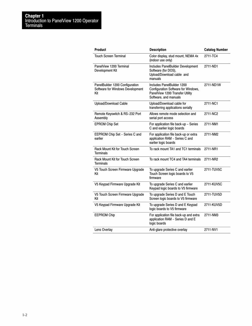
Touch Screen Terminal ÁÁÁÁÁÁÁÁÁÁÁÁÁÁÁÁÁÁÁÁÁÁÁÁÁÁÁÁÁ
Color display, stud mount, NEMA 4x(indoor use only)
ÁÁÁÁÁÁÁÁÁÁÁÁÁÁÁ
2711�TC4
ÁÁÁÁÁÁÁÁÁÁÁÁÁÁÁÁÁÁÁÁÁÁÁÁÁÁÁÁÁÁ
PanelView 1200 TerminalDevelopment Kit
ÁÁÁÁÁÁÁÁÁÁÁÁÁÁÁÁÁÁÁÁÁÁÁÁÁÁÁÁÁÁ
Includes PanelBuilder DevelopmentSoftware (for DOS),Upload/Download cable andmanuals
ÁÁÁÁÁÁÁÁÁÁÁÁÁÁÁ
2711�ND1
ÁÁÁÁÁÁÁÁÁÁÁÁÁÁÁÁÁÁÁÁÁÁÁÁÁÁÁÁÁÁÁÁÁÁÁÁÁÁÁÁ
PanelBuilder 1200 ConfigurationSoftware for Windows DevelopmentKit
ÁÁÁÁÁÁÁÁÁÁÁÁÁÁÁÁÁÁÁÁÁÁÁÁÁÁÁÁÁÁÁÁÁÁÁÁÁÁÁ
Includes PanelBuilder 1200Configuration Software for Windows,PanelView 1200 Transfer UtilitySoftware, and manuals
ÁÁÁÁÁÁÁÁÁÁÁÁÁÁÁÁÁÁÁÁ
2711�ND1W
ÁÁÁÁÁÁÁÁÁÁÁÁÁÁÁÁÁÁÁÁÁÁÁÁÁÁÁÁÁÁ
Upload/Download CableÁÁÁÁÁÁÁÁÁÁÁÁÁÁÁÁÁÁÁÁÁÁÁÁÁÁÁÁÁ
Upload/Download cable fortransferring applications serially
ÁÁÁÁÁÁÁÁÁÁÁÁÁÁÁ
2711�NC1
ÁÁÁÁÁÁÁÁÁÁÁÁÁÁÁÁÁÁÁÁÁÁÁÁÁÁÁÁÁÁ
Remote Keyswitch & RS-232 PortAssembly
ÁÁÁÁÁÁÁÁÁÁÁÁÁÁÁÁÁÁÁÁÁÁÁÁÁÁÁÁÁ
Allows remote mode selection andserial port access
ÁÁÁÁÁÁÁÁÁÁÁÁÁÁÁ
2711�NC2
ÁÁÁÁÁÁÁÁÁÁÁÁÁÁÁÁÁÁÁÁ
EPROM Chip Set ÁÁÁÁÁÁÁÁÁÁÁÁÁÁÁÁÁÁ
For application file back�up - SeriesC and earlier logic boards
ÁÁÁÁÁÁÁÁÁÁ2711�NM1
ÁÁÁÁÁÁÁÁÁÁÁÁÁÁÁÁÁÁÁÁÁÁÁÁÁÁÁÁÁÁÁÁÁÁÁÁÁÁÁÁ
EEPROM Chip Set - Series C andearlier
ÁÁÁÁÁÁÁÁÁÁÁÁÁÁÁÁÁÁÁÁÁÁÁÁÁÁÁÁÁÁÁÁÁÁÁÁÁÁÁ
For application file back�up or extraapplication RAM - Series C andearlier logic boards
ÁÁÁÁÁÁÁÁÁÁÁÁÁÁÁÁÁÁÁÁ
2711�NM2
ÁÁÁÁÁÁÁÁÁÁÁÁÁÁÁÁÁÁÁÁ
Rack Mount Kit for Touch ScreenTerminals
ÁÁÁÁÁÁÁÁÁÁÁÁÁÁÁÁÁÁ
To rack mount TA1 and TC1 terminals ÁÁÁÁÁÁÁÁÁÁ
2711�NR1
ÁÁÁÁÁÁÁÁÁÁÁÁÁÁÁÁÁÁÁÁÁÁÁÁÁÁÁÁÁÁ
Rack Mount Kit for Touch ScreenTerminals
ÁÁÁÁÁÁÁÁÁÁÁÁÁÁÁÁÁÁÁÁÁÁÁÁÁÁÁÁÁ
To rack mount TC4 and TA4 terminalsÁÁÁÁÁÁÁÁÁÁÁÁÁÁÁ
2711�NR2
ÁÁÁÁÁÁÁÁÁÁÁÁÁÁÁÁÁÁÁÁÁÁÁÁÁÁÁÁÁÁ
V5 Touch Screen Firmware UpgradeKit
ÁÁÁÁÁÁÁÁÁÁÁÁÁÁÁÁÁÁÁÁÁÁÁÁÁÁÁÁÁ
To upgrade Series C and earlierTouch Screen logic boards to V5firmware
ÁÁÁÁÁÁÁÁÁÁÁÁÁÁÁ
2711�TUV5C
ÁÁÁÁÁÁÁÁÁÁÁÁÁÁÁÁÁÁÁÁÁÁÁÁÁÁÁÁÁÁ
V5 Keypad Firmware Upgrade KitÁÁÁÁÁÁÁÁÁÁÁÁÁÁÁÁÁÁÁÁÁÁÁÁÁÁÁÁÁ
To upgrade Series C and earlierKeypad logic boards to V5 firmware
ÁÁÁÁÁÁÁÁÁÁÁÁÁÁÁ
2711�KUV5C
ÁÁÁÁÁÁÁÁÁÁÁÁÁÁÁÁÁÁÁÁ
V5 Touch Screen Firmware UpgradeKit
ÁÁÁÁÁÁÁÁÁÁÁÁÁÁÁÁÁÁ
To upgrade Series D and E TouchScreen logic boards to V5 firmware
ÁÁÁÁÁÁÁÁÁÁ2711�TUV5D
ÁÁÁÁÁÁÁÁÁÁÁÁÁÁÁÁÁÁÁÁÁÁÁÁÁÁÁÁÁÁ
V5 Keypad Firmware Upgrade KitÁÁÁÁÁÁÁÁÁÁÁÁÁÁÁÁÁÁÁÁÁÁÁÁÁÁÁÁÁ
To upgrade Series D and E Keypadlogic boards to V5 firmware
ÁÁÁÁÁÁÁÁÁÁÁÁÁÁÁ
2711�KUV5D
ÁÁÁÁÁÁÁÁÁÁÁÁÁÁÁÁÁÁÁÁÁÁÁÁÁÁÁÁÁÁ
EEPROM Chip ÁÁÁÁÁÁÁÁÁÁÁÁÁÁÁÁÁÁÁÁÁÁÁÁÁÁÁÁÁ
For application file back�up and extraapplication RAM - Series D and Elogic boards
ÁÁÁÁÁÁÁÁÁÁÁÁÁÁÁ
2711�NM3
ÁÁÁÁÁÁÁÁÁÁÁÁÁÁÁÁÁÁÁÁ
Lens OverlayÁÁÁÁÁÁÁÁÁÁÁÁÁÁÁÁÁÁ
Anti�glare protective overlayÁÁÁÁÁÁÁÁÁÁ2711�NV1
Introduction to PanelView 1200 OperatorTerminals
Chapter 1
1-3
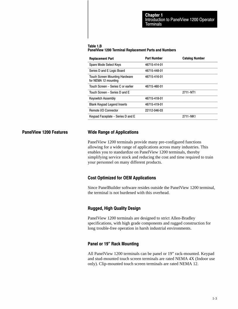
Table 1.BPanelView 1200 Terminal Replacement Parts and Numbers
Replacement Part Part Number Catalog Number
ÁÁÁÁÁÁÁÁÁÁÁÁÁÁÁÁÁÁÁÁ
Spare Mode Select Keys ÁÁÁÁÁÁÁÁÁÁÁÁÁÁ
46715�414�01 ÁÁÁÁÁÁÁÁÁÁÁÁÁÁÁÁÁÁÁÁÁÁÁÁ
ÁÁÁÁÁÁÁÁÁÁSeries D and E Logic Board ÁÁÁÁÁÁÁ
ÁÁÁÁÁÁÁ46715�448�01 ÁÁÁÁÁÁÁ
ÁÁÁÁÁÁÁÁÁÁÁÁÁÁÁÁÁÁÁÁÁÁÁÁÁÁÁÁ
Touch Screen Mounting Hardware for NEMA 12 mounting
ÁÁÁÁÁÁÁÁÁÁÁÁÁÁ
46715�416�01 ÁÁÁÁÁÁÁÁÁÁÁÁÁÁÁÁÁÁÁÁÁÁÁÁ
ÁÁÁÁÁÁÁÁÁÁÁTouch Screen - Series C or earlierÁÁÁÁÁÁÁÁÁÁÁÁÁÁ46715�460�01
ÁÁÁÁÁÁÁÁÁÁÁÁÁÁ
Touch Screen - Series D and E 2711-NT1ÁÁÁÁÁÁÁÁÁÁÁÁÁÁÁÁÁÁÁÁÁKeyswitch Assembly
ÁÁÁÁÁÁÁÁÁÁÁÁÁÁ46715�418�01
ÁÁÁÁÁÁÁÁÁÁÁÁÁÁÁÁÁÁÁÁÁÁÁÁ
ÁÁÁÁÁÁÁÁÁÁÁBlank Keypad Legend InsertsÁÁÁÁÁÁÁÁÁÁÁÁÁÁ46715�419�01
ÁÁÁÁÁÁÁÁÁÁÁÁÁÁÁÁÁÁÁÁÁÁÁÁ
ÁÁÁÁÁÁÁÁÁÁÁRemote I/O ConnectorÁÁÁÁÁÁÁÁÁÁÁÁÁÁ22112�046�03
ÁÁÁÁÁÁÁÁÁÁÁÁÁÁ
Keypad Faceplate - Series D and E 2711-NK1
Wide Range of Applications
PanelView 1200 terminals provide many pre-configured functionsallowing for a wide range of applications across many industries. Thisenables you to standardize on PanelView 1200 terminals, therebysimplifying service stock and reducing the cost and time required to trainyour personnel on many different products.
Cost Optimized for OEM Applications
Since PanelBuilder software resides outside the PanelView 1200 terminal,the terminal is not burdened with this overhead.
Rugged, High Quality Design
PanelView 1200 terminals are designed to strict Allen-Bradleyspecifications, with high grade components and rugged construction forlong trouble-free operation in harsh industrial environments.
Panel or 19" Rack Mounting
All PanelView 1200 terminals can be panel or 19” rack-mounted. Keypadand stud-mounted touch screen terminals are rated NEMA 4X (Indoor useonly). Clip-mounted touch screen terminals are rated NEMA 12.
PanelView 1200 Features

Introduction to PanelView 1200 OperatorTerminals
Chapter 1
1-4
12" Monochrome or Color Display
All PanelView 1200 terminals have a 12” display in monochrome (amber)or color. Color terminals can display 8 colors at a time from a choice of 16.
Direct Connection to any Allen�Bradley PLC Remote I/O Link
You can integrate a PanelView 1200 terminal quickly and easily into anyPLC system capable of supporting the Allen-Bradley 1771 Remote I/OLink.
A PanelView 1200 terminal appears as one or more PLC I/O racks on anAllen-Bradley PLC Remote I/O link; it can be configured as up to 8different racks—or fractional racks—with any valid PLC rack numbers.
Communications between the PLC controller and the PanelView 1200terminal are provided through the discrete I/O image table area, and up to 5block transfers (up to 32 words per block). Block transfers allow you totransfer more information at a time than does discrete I/O. The PanelView 1200 terminals can also communicate to the SLC-5/02controller through the use of the 1747-SN module.
Direct or Data Highway Plus and Remote I/O Downloading
Application files can be downloaded from the development computer tothe terminal via the Upload/Download cable (an RS-232 connection), orvia a Data Highway Plus, using the PLC-5 Pass-Through feature.
By using the Data Highway Plus for downloading, you can download toseveral terminals from a single development computer without having togo from terminal to terminal, connecting the Upload/Download cable foreach one.
Factory Installed Battery Provides Extended Back�up
The built-in battery maintains power to the terminal’s memory so theapplication file is not lost when the terminal is switched off. PanelView1200 terminals come equipped with a RAM memory chip that requiresminimal power from the lithium battery. Also, the battery is not burdenedwhen AC power is applied to the terminal. This provides exceptional lifefor the battery, which is expected to last for the life of the terminal.
Introduction to PanelView 1200 OperatorTerminals
Chapter 1
1-5
User�Definable Keys
The keypad terminal has 21 user-definable keys on its front panel. Eachone can perform a variety of operations—from turning on PLC input bitsto changing screens. PanelView 1200 terminals are extremely flexible:each key can be assigned a different function for each screen.
Custom Keypad Legend Inserts
The function keys on keypad terminals are pre-labeled at the factory, butyou can create key labels to suit your application. The included Legend Kitprovides blank card material that can be written on with most types ofmarkers or paste-on labels. Replacing the labels on the terminals is a quickand easy task.
Touch Screen Terminal for Simplicity and Space Saving
A touch-sensitive surface overlays the monitor on the touch screenterminal. Selections are made by touching the display directly. Since akeypad is not required, these terminals require less panel space.
Message and Alarm Handling Utilities
A PanelView 1200 terminal application can be set up with stored messagesthat can be triggered by the PLC controller. There are three kinds ofmessage displays:
Local Message Displays can appear in any free location on a specificscreen (875 messages maximum)
Information Windows can pop up regardless of the screen currentlydisplayed (496 messages maximum)
Alarm Windows can pop up regardless of the screen currently displayed(496 messages maximum)
For each type of message displayed—local, information or alarm—there isa message list. Using PanelBuilder software, you can add or edit messages.Messages are numbered and listed in numerical order in the message list.
See your PanelBuilder 1200 Configuration Software for Windows UserManual for more information on PanelBuilder 1200 ConfigurationSoftware for Windows. See your PanelBuilder Development Software UserManual for more information on PanelBuilder Development Software forDOS.

Introduction to PanelView 1200 OperatorTerminals
Chapter 1
1-6
Built�in Clock
The battery-backed clock runs even when the terminal is powered down.PanelView 1200 can display the current time and date and can send it tothe PLC controller. The clock may also be set by the PLC controller.
Audio and Visual Feedback
A PanelView 1200 terminal can be configured to:
activate a beeper each time a function button or touch cell is pressed
light up a screen button (if it has a border) when its function key ortouch cell is pressed.
allow the PLC controller to activate the beeper at the terminal
allow Alarm Messages to activate the beeper at the terminal
Alarm Relay
You can attach a horn or a warning light to the PanelView 1200 terminal’salarm relay. Relay connections are made via the terminal block labeled“Alarm Contacts” at the rear of the terminal. Specific alarm messages, or aPLC program, can then trigger the relay.
Attention The Alarm Relay must be used only as a warningsystem, not for control purposes.
RS�232 Port
All PanelView 1200 terminals include one RS-232 port for printing on-linealarm messages, uploading and downloading application files, and printingscreens.
Introduction to PanelView 1200 OperatorTerminals
Chapter 1
1-7
PanelView 1200 Terminal Diagnostics
When a PanelView 1200 terminal starts up, it performs a number of faultdetection tests. The PanelView 1200 terminal also performs continuoustests for fault conditions when it is communicating online with the PLCcontroller. In the event of a fault, a message appears, pinpointing the exactnature of the fault.
An operator can also initiate diagnostic tests from the terminal.
For a description of the diagnostic tests, and the various fault conditions,refer to Chapter 2, PanelView 1200 Terminal Functions, in this manual.
Optional hardware is available that you may find convenient to use witheither type of the PanelBuilder software and the PanelView 1200 terminal.For catalog numbers see tables 1.A and 1.B.
Upload/Download Cable
The Upload/Download cable connects the development computer’s RS-232Port to the PanelView 1200 terminal’s RS-232 Port. You use it to transferapplications serially between the development computer and thePanelView 1200 terminal If you have a number of terminals, you may wantto order more than one Upload/Download cable.
Optional Remote Keyswitch & RS�232 Port Assembly
On the back of all PanelView 1200 terminals is a Mode Select Keyswitchand RS-232 Port. The Remote Keyswitch and RS-232 Port Assemblyallows you to mount the port and keyswitch to the front of your controlpanel while maintaining a NEMA 4X seal. This is convenient if you don’thave easy access to the rear of the PanelView 1200 terminal. See Chapter3, Installing Your PanelView 1200 Terminal, for details on mounting anddimensions.
Optional EEPROM or EPROM for Back�up or Additional ApplicationMemory
Earlier PanelView 1200 terminals contained two sockets for optionalEPROM or EEPROM chips. Series D and E PanelView 1200 terminalshave one socket for an optional EPROM/EEPROM, called the user PROM.
Options and Accessories

Introduction to PanelView 1200 OperatorTerminals
Chapter 1
1-8
an EPROM can be used for application file back-up. The application fileis programmed into the EPROM with a PROM burner. Onceprogrammed, it cannot be erased or overwritten.
an EEPROM can be used for application file back-up or for extraapplication memory
when the EEPROM is used for application back-up, the downloadedapplication file is automatically copied to the EEPROM during thedownload operation
an EEPROM can also be used to increase the memory available forapplication file storage from 64K to 128K. If the EEPROM is used inthis way, it cannot be used as back-up for the application file.
Functional Variations Among Terminal Types
The terminals are configured almost identically with these exceptions:
buttons are set up differently on keypad terminals and touch screenterminals
certain screen objects are specific to keypad terminals, others to touchscreen terminals. For more information on objects see yourPanelBuilder 1200 Configuration Software for Windows User Manual,or your PanelBuilder Development Software User Manual.
foreground and background colors can be assigned only for colorPanelView 1200 terminals. Inverse video and intensity settings areassigned for monochrome terminals
The keypad terminal has:
21 user-definable function keys
a keypad for entering numeric values
up, down, left and right arrow keys
Home, Enter, Select, Cancel, Raise, Lower and Backspace keys
The user-definable function keys on keypad terminals are pre-labeled at thefactory, but you can create key labels (legends) to suit your application.The replacement key legends slide in from the rear of the faceplate. Theincluded Legend Kit provides blank card material that can be written onwith most types of markers or paste-on labels.
Keypad Terminals

Introduction to PanelView 1200 OperatorTerminals
Chapter 1
1-9
You can also configure the terminal to beep when a key is pressed.
Figure 1.1Keypad Terminal
NumericKeypad
Function Keys 21000
Special Keys
7 8 9
4 5 6
1 2 3
• 0 -
�
� HOME �
�
CANCEL
SELECTRaise
Lower
F21
F20
F18
F17
F16
F8
F15
F7
F14
F6
F13
F5
F12
F4
F11
F3
F10
F2
F9
F1
PanelView
��F19
Function Keys
When creating screens, you can assign any of the 21 function keys toobjects so that they can perform a wide variety of functions, ranging fromturning on PLC input bits to changing screens. Keys can have differentfunctions for each screen created.
Numeric Keypad
The keypad terminal has a numeric input keypad that includes numberkeys, Enter, Backspace, – (negative), and . (decimal) keys. When youneed to make a numeric entry, you call up a pop-up Numeric EntryScratchpad that displays the numbers as you type.
The Numeric Entry Scratchpad is displayed on the screen any time theoperator is required to enter numeric data and send it to a PLC controller.

Introduction to PanelView 1200 OperatorTerminals
Chapter 1
1-10
Special Keys
There are a series of special keys on the keypad terminal:
the arrow keys are used with the Set Bit and Numeric Cursor Points andthe ASCII Input object
Home, Select work with the Set Bit and Numeric Input Cursor Points
Cancel is designed to be used with all numeric keypads, Numeric Inputand Set Bit Cursor Points.
Raise and Lower are used with Numeric Input Cursor Points only.
The three blank keys at the bottom right are reserved for futuredevelopment, and are not configurable.
For more details, see your PanelBuilder Development Software UserManual, or your PanelBuilder 1200 Configuration Software for WindowsUser Manual.
Touch screen terminals are simple to use: an operator presses a selectiondirectly on the screen to carry out the desired task.
Figure 1.2Touch Screen Terminal
21003
PanelView
Touch Screen Terminals

Introduction to PanelView 1200 OperatorTerminals
Chapter 1
1-11
The touch screen terminal contains 120 touch cells. Each touch cell is 2characters high by 8 characters wide. You can configure the terminal tobeep when a touch cell is pressed.
20002
16 characters fit in one touch cell
Touch cells are grouped to create different types and sizes of buttons. Thefollowing figure illustrates a single touch cell ON button with doubleheight and double width characters, and a solid border. You can activateinput functions by touching the appropriate object on the touch screen.
Button
Border
20216
The objects, windows and PLC control options are listed in three groups:those used on both keypad and touch screen terminals, those used forkeypad terminals only, and those used for touch screen terminals only.
You will note that the objects are identified as either dynamic or static.Dynamic objects interact with the PLC controller; static objects do not.
For complete details on all objects, windows and options that can becontrolled from the PLC controller, refer to your PanelBuilderDevelopment Software User Manual, or your PanelBuilder 1200Configuration Software for Windows User Manual.
The following table lists the objects, and indicates which terminal typesthey are suited for. It also shows whether the object is dynamic or static.
Objects, Windows, and PLCControl Options
Introduction to PanelView 1200 OperatorTerminals
Chapter 1
1-12
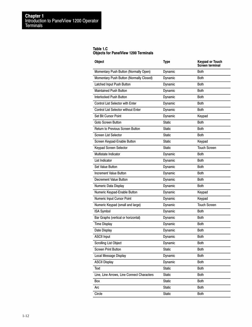
Table 1.CObjects for PanelView 1200 Terminals
Object Type Keypad or TouchScreen terminal
Momentary Push Button (Normally Open) Dynamic Both
Momentary Push Button (Normally Closed) Dynamic Both
Latched Input Push Button Dynamic Both
Maintained Push Button Dynamic Both
Interlocked Push Button Dynamic Both
Control List Selector with Enter Dynamic Both
Control List Selector without Enter Dynamic Both
Set Bit Cursor Point Dynamic Keypad
Goto Screen Button Static Both
Return to Previous Screen Button Static Both
Screen List Selector Static Both
Screen Keypad�Enable Button Static Keypad
Keypad Screen Selector Static Touch Screen
Multistate Indicator Dynamic Both
List Indicator Dynamic Both
Set Value Button Dynamic Both
Increment Value Button Dynamic Both
Decrement Value Button Dynamic Both
Numeric Data Display Dynamic Both
Numeric Keypad�Enable Button Dynamic Keypad
Numeric Input Cursor Point Dynamic Keypad
Numeric Keypad (small and large) Dynamic Touch Screen
ISA Symbol Dynamic Both
Bar Graphs (vertical or horizontal) Dynamic Both
Time Display Dynamic Both
Date Display Dynamic Both
ASCII Input Dynamic Both
Scrolling List Object Dynamic Both
Screen Print Button Static Both
Local Message Display Dynamic Both
ASCII Display Dynamic Both
Text Static Both
Line, Line Arrows, Line Connect Characters Static Both
Box Static Both
Arc Static Both
Circle Static Both
Introduction to PanelView 1200 OperatorTerminals
Chapter 1
1-13
The following objects can be displayed on both the keypad terminal andthe touch screen terminal:
Momentary Push Button (Normally Open) turns on (sets to 1) a PLCinput control bit, as long as the button is held.
Momentary Push Button (Normally Closed) resets a PLC inputcontrol bit that is normally set to 1. This bit stays off as long as thebutton is pressed.
Latched Input Push Button turns on a PLC input control bit and holdsthe bit on until the PanelView 1200 terminal sees a PLC output bit(handshake bit) turn on.
Maintained Push Button turns on a specific PLC input control bit untilthe button is pressed a second time.
Interlocked Push Buttons are several push buttons functioning as agroup. When you press one of the buttons, it cancels the other buttonsand makes the selection. The PLC controller is informed—via acommon PLC input address—which button in the group is the currentlyselected option.
Control List Selector with Enter contains a vertical list of operatorchoices. An operator can use the object’s Up Cursor and Down Cursorbuttons to move an arrow through the available selections. The selectionis sent to the PLC controller only when the Enter button is pressed.
Control List Selector without Enter contains a vertical list of choices.The operator uses the object’s Up Cursor and Down Cursor buttons tomove through the available selections. The current selection isautomatically sent to the PLC controller via the object’s PLC inputcontrol address.
“Goto Screen” Button allows the operator to switch to an assignedscreen.
“Return To Previous Screen” Button switches back to the previousscreen.
Screen List Selector allows an operator to choose a screen from a list.
Multistate Indicator is a display area with up to sixteen differentdisplay states, each with a unique combination of text, colors andattributes. The value in the PLC address determines which state isdisplayed.
Objects Common to AllPanelView 1200 Terminals

Introduction to PanelView 1200 OperatorTerminals
Chapter 1
1-14
List Indicator displays a list of PLC states and highlights the currentstate. The value of the PLC address determines the item that will behighlighted in the list.
Set Value Button transfers a pre-defined value to the PLC controller viathe assigned PLC input address.
Increment Value Button increases the value stored at a PLC inputaddress each time the button is pushed. If the button is held down, thePLC controller input value continues to increase to a pre-assigned upperlimit.
Decrement Value Button decreases the value stored at a PLC inputaddress each time the button is pushed. If the button is held down, thePLC controller value continues to decrease to a pre-assigned bottomlimit.
Numeric Data Display displays the current value of an assigned PLCcontroller address (binary, BCD, or integer). Scaling (Y=Mx+b) andother options can be used to display the number in appropriate units.
ISA Symbols (32 in total) allow you to assign display attributes to fourpossible states for each symbol object. The symbols have two sizes:large and small.
Bar Graphs can be used to monitor changing conditions, such astemperature or fluid levels. Each graph can be up to 80 characters wideand 24 characters high.
Time Display can be located anywhere on the screen.
Date Display can be located anywhere on the screen.
ASCII Input allows the PanelView 1200 terminal operator to sendASCII strings of up to 64 characters to the assigned PLC input address.
Scrolling List object is an extended and enhanced control listselector/list indicator that is not limited by the number of lines on thescreen. The Scrolling List can consist of any combination of localmessage display, multistate indicator, and numeric display lists with upto 999 items in each list. The Scrolling List object reduces PLC ladderlogic and addressing typically needed to display and edit large amountsof data.
This object can be used to control and monitor sequential operations inboth auto and manual modes or to provide operators with a selectionlist.
Introduction to PanelView 1200 OperatorTerminals
Chapter 1
1-15
Screen Print Button allows an operator to print any screen currentlydisplayed on the PanelView 1200 terminal.
Local Message Display can be defined as a rectangular area of any size,and placed in any location on the PanelView 1200 terminal screen. APLC control address is assigned to the object, allowing the PLCcontroller to trigger any one of up to 875 messages to appear in thisarea.
ASCII Display is used to display a character string, sent from the PLCcontroller, directly on the PanelView 1200 terminal. The display isupdated whenever the string changes.
Text is used for screen titles, to provide instructions, or for any text thatis not bound to an object.
Lines (Horizontal, vertical and diagonal) are used to illustrate, and toseparate sections of screens.
Line Arrows are used to illustrate.
Line Connect Characters are used to connect lines and lines andobjects.
Boxes are graphic objects like lines, which can surround other objects orsimply illustrate.
Arcs are used to illustrate quarter, semi, and three quarter circles, aswell as circles. They can also be used to connect line objects to formrounded corners.
Circles are composed of four arcs. They are used to illustrate.
The following objects can be displayed only on a keypad terminal:
Numeric Input Cursor Point consists of a numeric display and acursor character. This object can be used to enter numbers into an arrayof numeric fields similar to an array of thumb-wheel switches on acontrol panel. This object has an associated PLC input address in whichthe value is communicated to the PLC controller.
Numeric Keypad-Enable Button pops up the Numeric EntryScratchpad in which the operator can enter a number. The number isthen stored in the specified PLC input address.
Screen Keypad-Enable Button pops up the Numeric Entry Scratchpadin which the operator can enter a screen number. The screen with thatnumber is displayed.
Objects for the KeypadTerminal
Introduction to PanelView 1200 OperatorTerminals
Chapter 1
1-16
Set Bit Cursor Point consists of a bit and a cursor character. Thisobject is used to “point” to a screen character. Several set bit cursorpoints can be in the same screen. Each one can have a different(user-defined) pointer; only the current pointer is visible and blinking.The current cursor point’s input bit is always on, so the PLC controlleralways “knows” the current selection.
Both the set bit and numeric input cursor points can be used on the samescreen.
The following objects can be displayed only on a touch screen terminal:
Keypad Screen Selector allows an operator to display a screen byentering the screen number. The selector is available in large and smallsizes.
Numeric Keypad is used to send a value to the PLC controller. A PLCinput address is assigned to each Numeric Keypad; the value that theoperator enters is stored at this address. The keypad is available in largeand small sizes.
The Information and Alarm Windows can pop up on the screen at any timeto display important information:
Information Window displays a message when triggered by the PLCcontroller. The window remains until the operator presses the Clearbutton, or until the PLC controller clears it. There can be as many as496 different messages for the Information Window.
Alarm Window is similar to the Information Window but with manyadditional features. Each message can be configured to sound the audioindicator (beeper), trip the alarm relay or print a message on a printer.
Alarms are time and date stamped and listed in the order they occur. Theoperator can acknowledge the alarm, clear the display, silence the alarm,view the Alarm History Screen, or view the Alarm Status Screen. Therecan be as many as 496 different messages for the Alarm Window.
Objects for the Touch ScreenTerminal
Information and AlarmWindows

Introduction to PanelView 1200 OperatorTerminals
Chapter 1
1-17
The following options can be controlled by the PLC controller:
PLC Controlled Audio allows the PLC controller to control thePanelView 1200 terminal’s audio beeper. A PLC bit address is assigned.When the PLC controller sets this bit, the terminal’s beeper is activated.This does not interfere with the Alarm Window’s use of the beeper.
PLC Controlled Alarm Relay allows the PLC controller to control thePanelView 1200 terminal’s alarm relay. A PLC bit address is assigned,and when the PLC controller sets this bit, the terminal’s alarm relay isenergized. This does not interfere with the Alarm Window’s use of therelay.
PLC Controlled Alarm Quantity/Accum Time Reset allows the PLCcontroller to reset the alarm count and the accumulated time-in-alarmtotal. These totals are shown in the Alarm Status screen.
PLC Controlled Screen Number allows the PLC controller to controlwhich screen is displayed. When the PLC controller puts a screennumber in an assigned address, the PanelView 1200 terminal displaysthe screen. This PLC controlled screen change always has precedenceover operator-controlled screen changes, and operator-generated screenchanges are allowed only if the PLC address contains 0.
PLC Controlled Screen Print allows the PLC controller to trigger aprintout of the screen displayed on the PanelView 1200 terminal.
PLC Controlled Time and Date allows the PanelView 1200 terminalto read the time and date from the PLC controller and set its internalclock.
PLC Controlled Clear Window clears the alarm window, the alarmbeeper and the alarm relay when a 0 to 1 transition is detected in theassigned PLC address bit.
PLC Controlled Silence Alarms silences the beeper and deactivatesthe alarm relay when a 0 to 1 transition is detected on this bit.
PanelView 1200 terminals can be connected to any Allen-Bradley 1771Remote I/O Link. Applicable host controllers include almost allAllen-Bradley Programmable Logic Controllers as well as certain IBMcomputers, VME Controllers, and the DEC Q-Bus interface.
Newly released Allen-Bradley programmable controllers that are not yetlisted will support PanelView 1200 terminals, as long as they support the1771 remote I/O.
Summary of PLC ControlledOptions
Applicable ProgrammableControllers and Connections
Introduction to PanelView 1200 OperatorTerminals
Chapter 1
1-18
The PanelView 1200 terminal appears as one or more I/O rack(s) to a PLCcontroller. It has the same configurability—and more—as a standard I/Orack. Refer to your applicable Allen-Bradley Programmable Controller andRemote I/O Scanner user’s manuals for various connection and remote I/Oconfiguration limitations.
PLC�5/11, 5/15, 5/20, 5/25, 5/30, 5/40, 5/60 and 5/250 Processors
You can connect one or more PanelView 1200 terminals directly to aPLC-5 Remote I/O Port (in Scanner Mode) along with other I/O racks. Ifthe PLC-5 Remote I/O Port is used in the adapter mode, one or morePanelView 1200 terminals can be connected to that PLC-5 along with otherI/O racks via a 1771-SN I/O Subscanner Module.
All Series C Rev A and later terminals can communicate at 230.4K baudwith any PLC-5 capable of supporting that baud rate.
If you are using a PLC-5/15 with partial rack addressing and blocktransfers, you must use PLC-5/15 series B, revision J or later.
PLC�5/10 Processor
One or more PanelView 1200 terminals can be connected to this processoralong with other I/O racks via the 1771-SN I/O Subscanner Module.
PLC�3 and PLC�3/10 Processors
One or more PanelView 1200 terminals can be connected directly to aPLC-3 or PLC-3/10 remote I/O Scanner along with other I/O racks.
If you are using a 1775-S4A Remote Scanner/Distribution panel, you mustuse Series B or higher.
PLC�2 Family Processors via 1771�SN or 1772�SD2
This includes the PLC-2/05, 2/15, 2/30, etc. One or more PanelView 1200terminals can be connected to these processors along with other I/O racksvia the 1771-SN I/O Subscanner Module.
If you are using a 1772-SD2 Scanner/Distribution panel, you must userevision 3 or later.
Introduction to PanelView 1200 OperatorTerminals
Chapter 1
1-19
SLC�5/02 via 1747�SN
One or more PanelView 1200 terminals can be connected to the 1747-SNI/O Subscanner Module (SLC–5/02 RIO connection) for the SLC–5/02processor. Each module provides an additional remote I/O link for the hostprogrammable controller. The rack range of the 1747-SN is 0 to 3.
Important No block transfers are possible with the SLC-5/02 and 1747-SNSeries A module.
1771�SN I/O Subscanner Module
One or more 1771-SN I/O Subscanner Modules can be installed in anystandard Allen-Bradley 1771 I/O rack. Each module provides an additionalremote I/O link for the host programmable controller. One or morePanelView 1200 terminals can be connected to any of the previouslymentioned processors along with other I/O racks via a 1771-SN I/OSubscanner Module. Refer to the 1771-SN Sub I/O Scanner Module DataSheet for specific details.
6008�SI IBM PC I/O Scanner
This module can be installed in an IBM PC� or compatible computer toprovide the computer with an Allen-Bradley 1771 Remote I/O Link. Youcan then connect Allen-Bradley Remote I/O racks and devices such as thePanelView 1200 terminal to this computer.
6008�SV VME I/O Scanner
This module can be installed in a VME backplane, providing the VMEcontroller with an Allen-Bradley 1771 Remote I/O Link. Allen-BradleyRemote I/O racks and devices such as the PanelView 1200 terminal canthen be connected to this VME controller.
6008�SQ DEC Q�BUS I/O Scanner
This module can be installed into a DEC Q-Bus controller to provide itwith an Allen-Bradley 1771 Remote I/O Link. Allen-Bradley Remote I/Oracks and devices such as the PanelView 1200 terminal can then beconnected to this controller.

Chapter
2
2-1
PanelView 1200 Terminal Functions
This chapter describes how to use the PanelView 1200 terminal’s twooperating modes and discusses the power-up and on-line tests that theterminal performs.
The PanelView 1200 terminal has two modes of operation: Configuremode and Run mode. Configure mode allows you to set up the terminal,and Run mode executes the application file. The PanelView 1200 terminalcommunicates with your PLC controller only when it’s in Run mode, so setit to this mode to monitor and control your PLC application.
The following illustration shows the rear panel of a PanelView 1200terminal. Note the location of the Mode Select Keyswitch, the brightnesscontrol, (Monochrome terminals), and the contrast control (Colorterminals).
Figure 1.1PanelView 1200 Terminal Rear Panels
Contrast Control
20153
BrightnessRS�232 PortMode Select KeyswitchPLC interface
Color Back Panel Monochrome Back Panel
RS�232 PortMode Select KeyswitchPLC interface
Fuses
Terminal Blocks
Fuses
Terminal Blocks
.............. ..............
The Brightness and the Contrast Controls adjust the terminal displayintensity. The Mode Select Keyswitch switches between Configuration andRun modes.
Contrast, Brightness and theMode Select Keyswitch

PanelView 1200 Terminal FunctionsChapter 2
2-2
With the optional Remote Keyswitch Assembly, you can access the ModeSelect Keyswitch and RS-232 port from the front of the rack where thePanelView 1200 terminal is mounted.
For more information on the Remote Keyswitch Assembly, see theinstruction sheet supplied with that option.
There are two types of faults: major faults and minor faults.
Major Faults
If the PanelView 1200 terminal detects a major fault, it enters Major Faultmode, and displays a message in the Major Fault Window, like this:
20201
While in Major Fault mode, the PanelView 1200 terminal cannot control ormonitor PLC controller functions. The operator must correct the problemand restart the terminal, or switch modes.
In Run mode, the faults logged to the Major Fault Window cannot becleared. If the terminal is set to Configuration mode, the Major Faultsdetected on power-up will be logged to the Minor Fault Window and canbe cleared from there.
While the PanelView 1200 terminal is in Major Fault mode, it appears as afaulted rack to the host PLC controller. You can design your PLC programto monitor the rack fault bits that correspond to the PanelView 1200terminal’s rack assignments, and to respond whenever these bits indicatethat the terminal isn’t operating or communicating properly. See your PLCcontroller and I/O scanner user’s documentation for details on how to usethe rack fault bits.
Minor Faults
If the PanelView 1200 terminal detects any minor faults, it disables normalinput entry and displays a message in the Minor Fault Window, like this:
Fault Conditions

PanelView 1200 Terminal FunctionsChapter 2
2-3
20318
Clear
The operator must press the Clear button to resume normal operation. TheClear button temporarily overrides the function that was previouslyassigned to the associated function key or touch cells. Minor faults do notaffect PLC communications.
When you power up the PanelView 1200 terminal, it performs a number oftests for major or minor faults to determine if any problems will affect itsoperation. If a major fault is detected, the system will enter Fault mode.
Once all the tests are successfully completed, the PanelView 1200 terminalwill go into Configuration or Run mode, depending on the Mode SelectKeyswitch setting.
Important If an application file is in battery-backed RAM and a usermemory PROM containing a different application file has been installed,the application file in RAM will be overwritten with the application file inuser PROM at power up.
Checksum and Read/Write Memory Tests
At powerup, the Checksum tests verify the firmware memory, theapplication file stored in the battery-backed RAM, and the user PROM.There is also a read-write memory test which verifies the battery-backedRAM.
if the firmware memory fails, it is a major fault
if the application file fails, it is a major fault
if the user PROM fails, it is a minor fault
if the battery-backed RAM fails, it is a major fault.
Power�Up Functions
PanelView 1200 Terminal FunctionsChapter 2
2-4
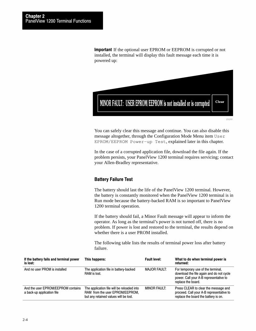
Important If the optional user EPROM or EEPROM is corrupted or notinstalled, the terminal will display this fault message each time it ispowered up:
20200
Clear
You can safely clear this message and continue. You can also disable thismessage altogether, through the Configuration Mode Menu item UserEPROM/EEPROM Power-up Test , explained later in this chapter.
In the case of a corrupted application file, download the file again. If theproblem persists, your PanelView 1200 terminal requires servicing; contactyour Allen-Bradley representative.
Battery Failure Test
The battery should last the life of the PanelView 1200 terminal. However,the battery is constantly monitored when the PanelView 1200 terminal is inRun mode because the battery-backed RAM is so important to PanelView1200 terminal operation.
If the battery should fail, a Minor Fault message will appear to inform theoperator. As long as the terminal’s power is not turned off, there is noproblem. If power is lost and restored to the terminal, the results depend onwhether there is a user PROM installed.
The following table lists the results of terminal power loss after batteryfailure.
If the battery fails and terminal poweris lost:
This happens: Fault level: What to do when terminal power isreturned:
And no user PROM is installed The application file in battery�backedRAM is lost.
MAJOR FAULT: For temporary use of the terminal,download the file again and do not cyclepower. Call your A�B representative toreplace the board.
And the user EPROM/EEPROM containsa back�up application file
The application file will be reloaded intoRAM from the user EPROM/EEPROM,but any retained values will be lost.
MINOR FAULT: Press CLEAR to clear the message andproceed. Call your A�B representative toreplace the board the battery is on.
PanelView 1200 Terminal FunctionsChapter 2
2-5
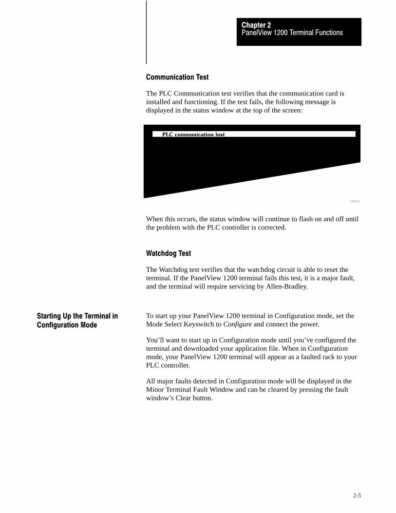
Communication Test
The PLC Communication test verifies that the communication card isinstalled and functioning. If the test fails, the following message isdisplayed in the status window at the top of the screen:
20314
PLC communication lost
When this occurs, the status window will continue to flash on and off untilthe problem with the PLC controller is corrected.
Watchdog Test
The Watchdog test verifies that the watchdog circuit is able to reset theterminal. If the PanelView 1200 terminal fails this test, it is a major fault,and the terminal will require servicing by Allen-Bradley.
To start up your PanelView 1200 terminal in Configuration mode, set theMode Select Keyswitch to Configure and connect the power.
You’ll want to start up in Configuration mode until you’ve configured theterminal and downloaded your application file. When in Configurationmode, your PanelView 1200 terminal will appear as a faulted rack to yourPLC controller.
All major faults detected in Configuration mode will be displayed in theMinor Terminal Fault Window and can be cleared by pressing the faultwindow’s Clear button.
Starting Up the Terminal inConfiguration Mode

PanelView 1200 Terminal FunctionsChapter 2
2-6
With the Mode Select Keyswitch set to Configure mode, the terminaldisplays the Configuration Mode Menu.
23593
Up
Cursor
Firmware Rev 05.00.00 06/21/93 (050900) 06/21/93 05:36:59 AM
Application File Name: DEMO 10801 Bytes Used, 52175 Bytes Free
CONFIGURATION MODE MENU
�
Down
Cursor
EnterInternal Version NumberDate IdentificationSoftware Version
Upload / Download
Serial Port
Rack Assignments
Access Codes
Audio Response
Alarm Relay
Preset Operations
Time and Date
Screen Saver
Screen Alignment
Stuck Button Timeout
User EPROM/EEPROM Power-up Test
Pass-Through Download Options
Unit Tests
Important The Configuration Mode Menu for a touch screen terminal alsocontains a False Depression Test which is discussed later in this chapter.
Upload/Download
There are two methods of uploading and downloading application files:
using the Upload/Download cable connected to the computer and theterminal’s RS-232 port
via a Data Highway Plus using the PLC-5’s Pass-Through feature
Uploading and Downloading instructions for application files are providedin the PanelBuilder Development Software User Manual, the PanelBuilder1200 Configuration Software for Windows User Manual, and thePanelView 1200 Transfer Utility User Manual.
If you are using an older version of PanelView 1200 firmware, see yourPanelBuilder software user manual for details on version compatibility.
The Configuration Mode Menu

PanelView 1200 Terminal FunctionsChapter 2
2-7
Important Downloading via the Pass-Through feature requiresconfiguration in PanelBuilder software or “Manual” configuration in theterminal’s Pass-Through Download Options menu, so that the networkinformation and the PanelView 1200 terminal’s location on the network iscorrect. Refer to the instructions in your PanelView 1200 Transfer UtilityUser Manual, the PanelBuilder Development Software User Manual or seethe Pass-Through Download Options section later in this chapter.
Serial Port
Use this menu item to set the serial communication port for downloadingor uploading application files, or for printing alarm messages or screens.
1 Choose Serial Port from the PanelView 1200 terminal’s ConfigurationMode menu by cursoring to Serial Port and pressing ENTER.
2 Press the Choose List button. The list of parameters in the window onthe left will toggle between these headings:
Upload/Download to configure the port for uploading ordownloading your application file
Printer to configure the port for printing alarm messages or screenson a serial printer.
The default settings for Upload/Download and Printer can be displayedin the Serial Port screen as follows:
Port Parameters Upload/Download Printer
Baud Rate 9600 9600
Parity None None
Data Bits 8 8
Stop Bits 1 1
Handshake Type Hardware Software
Auto�Line Feed Off (not configurable) On
Auto�Form Feed Off (not configurable) On
3 Using the Change Data button, set the desired baud rate, number ofbits, parity, etc.
4 When the desired values have been configured, press the Save & Exitbutton to save them permanently to RAM.
PanelView 1200 Terminal FunctionsChapter 2
2-8
Important The Auto Line Feed and Auto Form Feed parameters are notused for uploading/downloading, and cannot be changed. Although youcan choose 7 or 8 for the “Data Bits” option, always use 8 (the default), oryou won’t be able to transfer. The 7 data bits option applies only to printersettings.
You should not have to change the default settings for Upload/Download;the PanelBuilder software expects these settings. If you do change thesettings, be sure you set the PanelBuilder development computer’s serialport to match. See instructions for configuring the computer’s serial port inyour PanelBuilder software user manual, along with instructions foruploading and downloading.
For printer settings, refer to your printer’s manual.
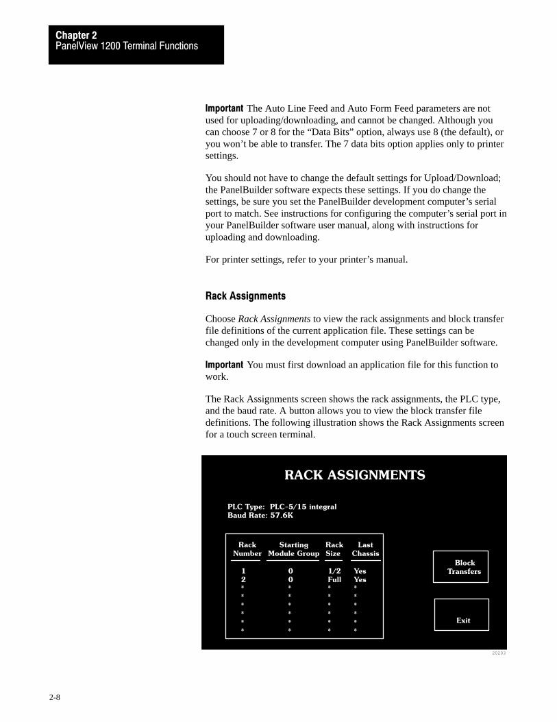
Rack Assignments
Choose Rack Assignments to view the rack assignments and block transferfile definitions of the current application file. These settings can bechanged only in the development computer using PanelBuilder software.
Important You must first download an application file for this function towork.
The Rack Assignments screen shows the rack assignments, the PLC type,and the baud rate. A button allows you to view the block transfer filedefinitions. The following illustration shows the Rack Assignments screenfor a touch screen terminal.
20203
RACK ASSIGNMENTS
PLC Type: PLC-5/15 integral
Baud Rate: 57.6K
Rack
Number
1
2
*
*
*
*
*
*
Starting
Module Group
0
0
*
*
*
*
*
*
Rack
Size
1/2
Full
*
*
*
*
*
*
Last
Chassis
Yes
Yes
*
*
*
*
*
*
Block
Transfers
Exit

PanelView 1200 Terminal FunctionsChapter 2
2-9
Access Codes
Choose Access Codes to assign up to eight security code settings. Oncesecurity codes are set, an operator will have to sign on using theappropriate code, in order to view screens that have assigned security.Screen security is assigned using PanelBuilder software.
Important If a screen is triggered by the PLC Controlled Screen option, orif it is the Power-up screen, that screen will be displayed and no accesscode will be requested.
The Operator Number display shows which operator’s code you aresetting. Press Next Operator to step through the eight available operatoraccess codes. The following illustration shows the Security Access Codesscreen on a touch screen terminal.
23733
SECURITY ACCESS CODES
Save & Exit
ENT
DEL
7 8 9
4 5 6
1 2 3
0CLR
Security Off
Security On
Next
Operator
Operator Number: 1Access Code: : 0000
To set an operator’s code on a touch screen terminal, enter a numericsequence in the keypad and press ENT (Enter). On keypad terminals, pressthe Change Access Code button to enable the Access Code keypadwindow, and use the function keypad to enter the access code.
You can also globally enable or disable all security by pressing SecurityOn/Security Off.
Once security codes are set, and security is enabled, operators can access arestricted PanelView 1200 screen only by entering the appropriate accesscode. If the code is invalid, the requested screen will not be displayed andthe operator will be informed which operator(s) have access to that screen.

PanelView 1200 Terminal FunctionsChapter 2
2-10
Audio Response
The PanelView 1200 terminal can sound a beep whenever you press anactive touch cell or keypad. The PLC controller can also trigger this audioindicator either directly with the PLC Controlled Audio, or through analarm message. The button, alarm and volume parameters can beconfigured from the Audio Response screen. For more information, seeyour PanelBuilder Development Software User Manual, or yourPanelBuilder 1200 Configuration Software for Windows User Manual.
Choose Audio Response to set:
the Touch Audio (for touch screen terminals) or Button Audio (forkeypad terminals) On or Off. The default setting is On. With the settingOn, the PanelView 1200 terminal beeps each time you press a button.
the Alarm Audio On or Off. The default setting is On. With the settingOn, both the PLC Controlled Audio bit and alarm messages can causethe PanelView 1200 terminal’s built-in audio indicator to beep. Settingthis to Off will disable both the alarm messages and the PLC ControlledAudio operation.
the Audio Volume level to High or Low. The default setting is High.
Alarm Relay
The alarm relay can be wired to an external alarm or warning light. Thisrelay is controlled by configuring an alarm message to activate the alarmrelay, or by defining a PLC Controlled Relay output bit (see yourPanelBuilder Development Software User Manual, or your PanelBuilder1200 Configuration Software for Windows User Manual).
Use Alarm Relay to enable or disable the relay, and to test the alarm relayby manually activating or deactivating it. The alarm relay test stops whenyou exit the Alarm Relay screen or toggle relay test to Off.
Preset Operations
In the PanelBuilder software, you can preset the initial states or values ofcertain retentive objects including Control Selectors, Interlocked PushButtons, Numeric Input objects, and other multi-state objects. These valuesare PLC input states that are initially transferred to the PLC controller andremain unchanged until altered by an operator.
Choose Preset Operations to set the operation of retentive objects.

PanelView 1200 Terminal FunctionsChapter 2
2-11
Attention If you upload an application file from a PanelView1200 terminal, the file will contain input states or values basedon the last use of the terminal—not necessarily the terminal’soriginal preset values. If you want the file to contain the presets,press the Load Presets button before uploading. This resets theterminal’s retentive input functions as well.
The following illustration shows the Preset Operations screen for a touchscreen terminal.
20204
PRESET OPERATIONS
Load
Presets
Save &
Exit
Last States
Power-up Values
Presets
For more information on retentive objects see your PanelBuilderDevelopment Software User Manual, or your PanelBuilder 1200Configuration Software for Windows User Manual.
Power-up Values can be set to Presets or Last States. Presets—thedefault setting—loads the initial presets, configured in PanelBuildersoftware, when the terminal is powered up. Last States causes theretentive objects to retain the state they had when the terminal waspowered down.
Important To save your selection, press Save & Exit before poweringdown or changing to Run mode.
Load Presets—Pressing the Load Presets button loads the initialpresets, configured in PanelBuilder software, into all retentive objects.

PanelView 1200 Terminal FunctionsChapter 2
2-12
Time and Date
Choose Time and Date to set the PanelView 1200 terminal’sbattery-operated clock.
Enter the time in 24 hour (Military) format: hh-mm-ss for keypad terminalshh:mm:ss for touch screen terminals
Enter the date in the format:mm-dd-yy for keypad terminalsmm/dd/yy for touch screen terminals
Screen Saver
The screen saver preserves the life of the PanelView 1200 terminal screenby blanking the screen when no buttons have been pressed for a period oftime.
Choose Screen Saver from the Configuration Mode menu to display thescreen and set the amount of time which should pass before the screenblanks. Elapsed time can range from 1 to 999 minutes. A setting of 0 (zero)disables the screen saver.
When the screen blanks, this message appears on a touch screen terminal:
20316
Touch The Screen To Activate
This message appears on a keypad terminal:
20315
Press Any Key To Activate
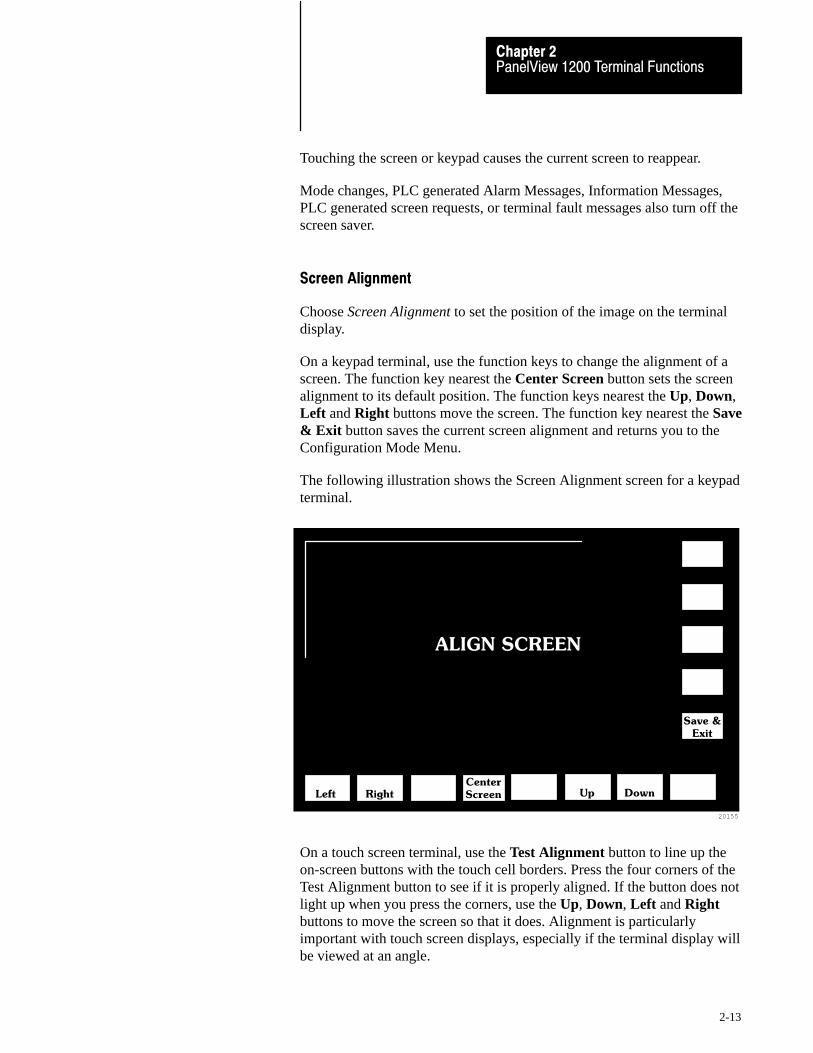
PanelView 1200 Terminal FunctionsChapter 2
2-13
Touching the screen or keypad causes the current screen to reappear.
Mode changes, PLC generated Alarm Messages, Information Messages,PLC generated screen requests, or terminal fault messages also turn off thescreen saver.
Screen Alignment
Choose Screen Alignment to set the position of the image on the terminaldisplay.
On a keypad terminal, use the function keys to change the alignment of ascreen. The function key nearest the Center Screen button sets the screenalignment to its default position. The function keys nearest the Up, Down,Left and Right buttons move the screen. The function key nearest the Save& Exit button saves the current screen alignment and returns you to theConfiguration Mode Menu.
The following illustration shows the Screen Alignment screen for a keypadterminal.
20155
ALIGN SCREEN
Left RightCenter
Screen Up Down
Save &
Exit
On a touch screen terminal, use the Test Alignment button to line up theon-screen buttons with the touch cell borders. Press the four corners of theTest Alignment button to see if it is properly aligned. If the button does notlight up when you press the corners, use the Up, Down, Left and Rightbuttons to move the screen so that it does. Alignment is particularlyimportant with touch screen displays, especially if the terminal display willbe viewed at an angle.
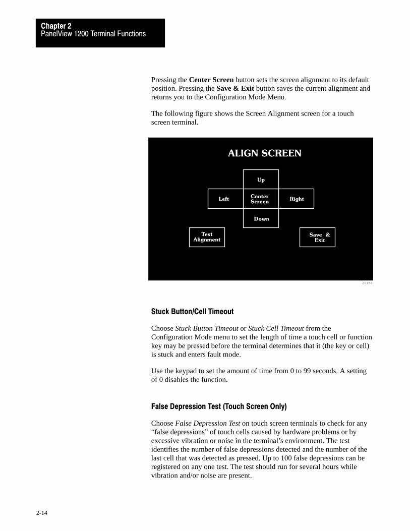
PanelView 1200 Terminal FunctionsChapter 2
2-14
Pressing the Center Screen button sets the screen alignment to its defaultposition. Pressing the Save & Exit button saves the current alignment andreturns you to the Configuration Mode Menu.
The following figure shows the Screen Alignment screen for a touchscreen terminal.
20156
ALIGN SCREEN
CenterScreen
Up
Down
TestAlignment
Left Right
Save &Exit
Stuck Button/Cell Timeout
Choose Stuck Button Timeout or Stuck Cell Timeout from theConfiguration Mode menu to set the length of time a touch cell or functionkey may be pressed before the terminal determines that it (the key or cell)is stuck and enters fault mode.
Use the keypad to set the amount of time from 0 to 99 seconds. A settingof 0 disables the function.
False Depression Test (Touch Screen Only)
Choose False Depression Test on touch screen terminals to check for any“false depressions” of touch cells caused by hardware problems or byexcessive vibration or noise in the terminal’s environment. The testidentifies the number of false depressions detected and the number of thelast cell that was detected as pressed. Up to 100 false depressions can beregistered on any one test. The test should run for several hours whilevibration and/or noise are present.

PanelView 1200 Terminal FunctionsChapter 2
2-15
The test starts running as soon as the screen is displayed; the number offalse depressions and the last cell detected are reset to zero.
The following illustration shows the False Depression Test screen.
20226
FALSE DEPRESSION TEST
Exit
False Depressions :
Last Cell Detected :
User EPROM/EEPROM Power�Up Test
PanelView 1200 terminals include a socket for an optional user PROM.
If your terminal does not have the optional user PROM installed or thePROM is corrupted, the terminal will, by default, show this minor faultmessage at power-up:
20200
Clear

PanelView 1200 Terminal FunctionsChapter 2
2-16
If you will not be installing the optional user PROM, this message servesno purpose. Disable it by choosing User EPROM/EEPROM Power-up Testfrom the Configuration menu, shown in the following illustration.
23647
Up
Cursor
Firmware Rev 05.00.00 06/21/93 (050900) 06/21/93 05:36:59 AM
Application File Name: DEMO 10801 Bytes Used, 52175 Bytes Free
CONFIGURATION MODE MENU
�
Down
Cursor
Enter
Upload / Download
Serial Port
Rack Assignments
Access Codes
Audio Response
Alarm Relay
Preset Operations
Time and Date
Screen Saver
Screen Alignment
Stuck Button Timeout
User EPROM/EEPROM Power-up Test
Pass-Through Download Options
Unit Tests
The User EPROM/EEPROM Power-up Test window will open:
23646
USER EPROM/EEPROM POWER-UP TEST
Test User EPROM/EEPROM
On Power-Up?
Save &
Exit
No
Yes

PanelView 1200 Terminal FunctionsChapter 2
2-17
Choose No to tell the terminal to bypass the User EPROM/EEPROM testat power-up. The following message will appear:
23627
WARNING: Choose �Yes" if EPROM/EEPROMS are installedClear
F8
If you install a user PROM later, be sure to reset the power-up test to Yes.
Pass�Through Download Options
The terminal Pass-Through Download Options allow you to configure thepass-through address manually from the terminal. These options also letyou instruct the terminal to restart automatically after a successfuldownload or to wait for operator confirmation before running a newapplication.
The pass-through download is retentive.
The following two illustrations shows the Pass-Through DownloadOptions screen for both touch screen and keypad terminals.
Choosing Manual Address Source
will disable the Terminal's
current application file.
Select Application to enable.
23662
PASS-THROUGH
DOWNLOAD OPTIONS
>Auto Restart
>Address Source
>PLC Type
>BAUD Rate
>Rack Number
>Starting Module
>Rack Size
>Last Chassis
>Module Group
>High/Low Byte
Up
Cursor
Save &
Exit
ENT
DEL
7 8 9
4 5 6
1 2 3
0CLR
Down
Cursor
Change
Data
Move the cursor upwards in theselection list. If the cursor is at thetop, this menu choice will move itto the bottom
Move the cursor downwards in theselection list. If the cursor is at the bottom,this menu choice will move it to the top
Move the cursor through the list of validoptions for the following items: Auto Restart,Address Sources, PLC Type, Baud Rate,Module Group and High/Low Byte
Save data and resolve incompatibilityproblems before exiting
Yes
Manual
PLC�5/250
230.4K
77
0
Full
Yes
7
High
Manual
Address
Source
Block
Transfer

PanelView 1200 Terminal FunctionsChapter 2
2-18
23663
PASS-THROUGH
DOWNLOAD OPTIONS
>Auto Restart
>Address Source
>PLC Type
>Baud Rate
>Rack Number
>Starting Module
>Rack Size
>Last Chassis
>Module Group
>High/Low Byte
Up
Cursor
Save &
Exit
Manual
Address
Source
Down
Cursor
Change
Data
Yes
Application
PLC�5/250
230.4K
77
0
Full
Yes
7
HighBlock
Transfer
Choosing Manual Address Source
will disable the Terminal's
current application file.
Select Application to enable.
On the keypad terminal, you can use the function keys to move the cursor.
F18 for Up Cursor
F19 for Down Cursor
F20 for Change Data
F21 for Save & Exit
Important On the keypad terminal, when Rack Number is selected and youpress the Change Data button, a keypad window opens. This windowdisappears when you enter a valid rack number. On the touch screenterminal, you can enter the Rack Number directly from the keypad whenRack Number is selected. For both terminal types, the number must be inOctal, and correspond to the PLC type selected.
Auto Restart
You can choose between Yes and No for the Auto Restart option. Thedefault is No.
If you choose Yes, PanelView 1200 will start executing the newapplication file as soon as the download is completed.
If you choose No, PanelView 1200 will wait for operator confirmationbefore it starts executing the new application.
PanelView 1200 Terminal FunctionsChapter 2
2-19
Address Source
You can choose between Application and Manual for the Address Source.The first time that you enter this screen, the default is Application. Whenyou re-enter the screen, the values that were previously saved appear.
When you set the Address Source to Manual, you invalidate the applicationfile. When you set the Address Source back to Application, you revalidatethe application file. It will execute normally.
Important After a successful download of an application file, viaPass-Through or serial port, the terminal automatically resets the AddressSource to Application, uses the application file parameters, and discardsthe Manual Address parameters.
Application—When you choose Application, the terminal uses theapplication file Pass-Through Address Source.
If the application file contains a pass-through configuration, its valuesare displayed in the Manual Address Source area. If the application filedoes not contain a pass-through configuration or there is no applicationfile present in the terminal, you will see asterisks displayed in theManual Address Source area. Without valid parameters in the AddressSource, the Pass-Through upload or download fails.
When you choose Application and then choose Save & Exit, theterminal saves the Auto-Restart setting only.
Manual—You must toggle the Address Source to Manual before youcan change any of the Manual Address Source entries.
When you choose Manual, the following message pops up:
Choosing Manual Address Source will disable the Terminal’s current application file. Select Application to enable
This message remains on your screen until you toggle the AddressSource to Application.

PanelView 1200 Terminal FunctionsChapter 2
2-20
If you toggle the Address Source to Manual but the current applicationfile has no Pass-Through configuration and a manual address has notbeen configured and saved previously, the asterisks will be replaced bythe following defaults:
PLC Type: PLC-5/25
Baud Rate: 57.6K
Rack Number: 1
Starting Module 0
Rack Size 1/4
Last Chassis Yes
Module Group: 0
High/Low Byte: Low
You must set the Module Group and High/Low Byte parameters tomatch the Pass-Through Block Transfer assignment in the file youintend to download using Pass-Through.
The Starting Module, Rack Size, and Last Chassis parameters enableyou to assign the terminal as one of the racks already configured in thePLC scan list. When replacing an existing PanelView terminal with anew one, you don’t need to reconfigure the PLC before or afterPass-Through Download.
When you set the Address Source to Manual and choose Save & Exit,the terminal validates the Manual Address Source and saves thePass-Through rack assignment setting and that of Auto-Restart. Theterminal also invalidates the existing application file to ensure that thenew manual Pass-Through rack assignment does not conflict withexisting application file rack assignments.
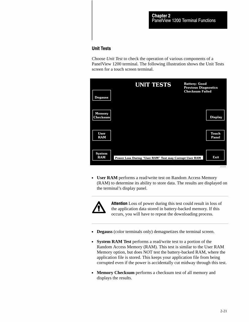
PanelView 1200 Terminal FunctionsChapter 2
2-21
Unit Tests
Choose Unit Test to check the operation of various components of aPanelView 1200 terminal. The following illustration shows the Unit Testsscreen for a touch screen terminal.
20205
UNIT TESTS Battery: Good
Previous Diagnostics
Checksum Failed
Memory
Checksum
Degauss
User
RAM
System
RAM Power Loss During �User RAM" Test may Corrupt User RAM
Display
Touch
Panel
Exit
User RAM performs a read/write test on Random Access Memory(RAM) to determine its ability to store data. The results are displayed onthe terminal’s display panel.
Attention Loss of power during this test could result in loss ofthe application data stored in battery-backed memory. If thisoccurs, you will have to repeat the downloading process.
Degauss (color terminals only) demagnetizes the terminal screen.
System RAM Test performs a read/write test to a portion of theRandom Access Memory (RAM). This test is similar to the User RAMMemory option, but does NOT test the battery-backed RAM, where theapplication file is stored. This keeps your application file from beingcorrupted even if the power is accidentally cut midway through this test.
Memory Checksum performs a checksum test of all memory anddisplays the results.

PanelView 1200 Terminal FunctionsChapter 2
2-22
Important If the User PROM is not installed, the test will indicate afailure at memory location 5000:0000 for Series C and earlier terminals,or at 4000:0000 for Series D and E terminals. This is normal.
Touch Panel (touch screen only) identifies touch cells that are difficultto activate or inoperable. During this test, the display shows 119 touchcells, in reverse video each with a distinct border on the inside of thecell. The 120th cell is occupied by the Exit button. Each cell is tested bypressing it. If the cell is working it changes to normal, then back toreverse video when pressed a second time.
The following illustration shows the Touch Panel Test screen.
20206
Exit
Function Keys identifies keypad terminal function keys that aredifficult to activate or inoperable. During this test, you’ll see a displayof all the function keys. Test each function key by pressing it. If thefunction key is working, the corresponding picture of the key willchange to reverse video. Press the key a second time to turn off thereverse video.
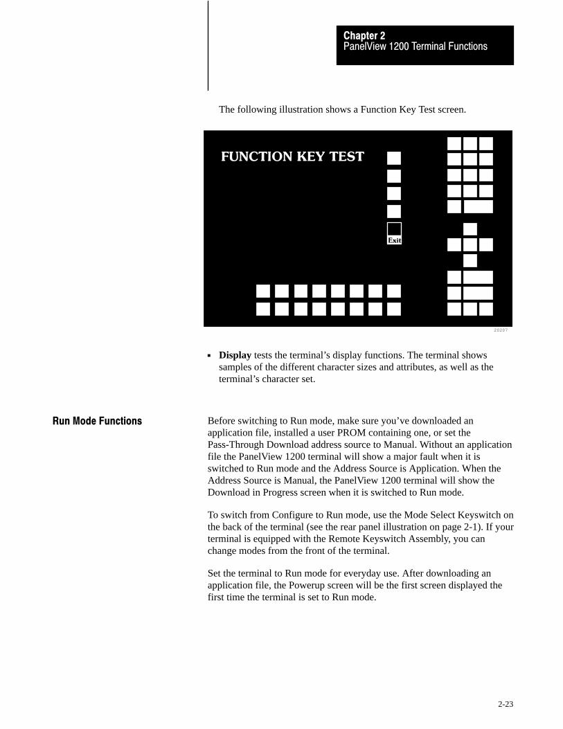
PanelView 1200 Terminal FunctionsChapter 2
2-23
The following illustration shows a Function Key Test screen.
20207
FUNCTION KEY TEST
Exit
Display tests the terminal’s display functions. The terminal showssamples of the different character sizes and attributes, as well as theterminal’s character set.
Before switching to Run mode, make sure you’ve downloaded anapplication file, installed a user PROM containing one, or set thePass-Through Download address source to Manual. Without an applicationfile the PanelView 1200 terminal will show a major fault when it isswitched to Run mode and the Address Source is Application. When theAddress Source is Manual, the PanelView 1200 terminal will show theDownload in Progress screen when it is switched to Run mode.
To switch from Configure to Run mode, use the Mode Select Keyswitch onthe back of the terminal (see the rear panel illustration on page 2-1). If yourterminal is equipped with the Remote Keyswitch Assembly, you canchange modes from the front of the terminal.
Set the terminal to Run mode for everyday use. After downloading anapplication file, the Powerup screen will be the first screen displayed thefirst time the terminal is set to Run mode.
Run Mode Functions
PanelView 1200 Terminal FunctionsChapter 2
2-24
The PanelView 1200 terminal performs periodic fault detection tests whileon-line with the PLC controller.
PLC Communication Timeout
If communication between the PLC controller and PanelView 1200terminal is interrupted, a special, flashing PLC Communication Lost statuswindow appears on the top line of the display.
The terminal will continue to operate, and operator-selected screens can bedisplayed. Displayed PLC data will show the last values received beforePLC communications were lost.
Invalid Screen Request
If the operator or PLC controller requests a non-existent screen, a minorfault message will appear pointing out the error. You will then have todebug your application file and/or PLC program.
Application Data Checksum
The Application Data Checksum test periodically checks the applicationfile in battery-backed RAM. If the PanelView 1200 terminal fails this test,the terminal enters Major Fault mode. You will need to download the fileagain to correct this problem.
Battery Failure
The terminal’s battery is monitored once every minute. When the testindicates battery failure, the PanelView 1200 terminal logs a minor fault.Refer to the battery failure table on page 2-4 for more information.
The PanelView 1200 terminal can print:
application screens
alarms displayed in both the Alarm Status and Alarm History Screens
a log of alarm messages
The terminal can print on any serial IBM (or compatible) text printer. Toset the communications parameters for the printer, choose Serial Port, thenChoose List to bring up the list of printer parameters.
On�line Diagnostic Testing
PanelView 1200 TerminalPrinting

PanelView 1200 Terminal FunctionsChapter 2
2-25
Important Not all graphic characters will appear in screen prints. SeeNon-Printable Characters, on page 2-26, for more details.
For details, see your PanelBuilder Development Software User Manual, oryour PanelBuilder1200 Configuration Software for Windows User Manual.
Print Priorities
If you try to print more than one report, screen, or alarm message at a time,the terminal will print in order of priority, saving the other print jobs in aqueue. See the following table for the print priority and the size of queueallotted for each type of print job.
Print Priority Print Job Number of Print Jobs That can be Queued
1 Screen Print none
2 Alarm Status Report 1
3 Alarm History Report 1
4 Alarm Messages 21
Note that screen print requests are ignored if the printer is already printinga screen. In the case of PLC controlled screen prints, the PLC can beinformed that the printer is busy when the PLC sends the print message: inPanelBuilder software, enable Screen Print Active to PLC Controller. Fordetails, refer to your PanelBuilder Development Software User Manual, oryour PanelBuilder 1200 Configuration Software for Windows UserManual.
Page Formatting
Each report starts on a new page. Each report (except the Alarm Messageprintout) starts with a title, including the time and date of printing. Theform feeds can be disabled by turning Auto Form Feed Off in the SerialPort configuration screen.
Alarm Messages are printed as the alarms are reported. The first alarmmessage that occurs after switching to Run Mode begins the AlarmMessage report. The Alarm Message report is preceded by a form feed, butfollowing that the alarm messages print one to a line, without page breaksor form feeds.

PanelView 1200 Terminal FunctionsChapter 2
2-26
Non�Printable Characters
If you are printing screens, some graphic characters will not be printed.Instead they will be replaced as follows:
ISA symbols, bar graphs, outer borders, arcs, diagonals and lineconnectors will be replaced by ASCII character 219 decimal illustratedbelow
23615
Character219
Character254
the first 32 characters, used for printer control, will be replaced byASCII character 254 decimal illustrated above
double width/height characters will be replaced by a single normal sizedcharacter and the appropriate number of blanks
Example: the letter A, displayed with double height and width,occupies an area 2 characters high and 2 characters wide. Once printed,the A will occupy the top left position leaving the other three charactersblank.
Printer Errors
Printer errors can’t be indicated to the terminal directly. The terminal candetect a print error only if the hardware or software handshaking is enabledand the appropriate serial lines are connected from the printer to theterminal. So, if the printer is out of paper or offline, and handshaking isenabled, the printer will signal the terminal to stop sending characters.
If the error persists for more than 30 seconds, a minor error will bereported asking the operator to ensure the printer is online. Once the erroris corrected, the terminal will continue sending characters to the printer.
Important If you intend to use a serial printer, you will have to constructyour own cable. Use the pinout shown in Figure 3-2 to construct thePanelView 1200 end of the cable. (Pin 20 detects the signal indicatingwhether the printer is on or offline when using hardware handshaking.)Consult your printer’s manual for the pinout at the printer end of the cable.
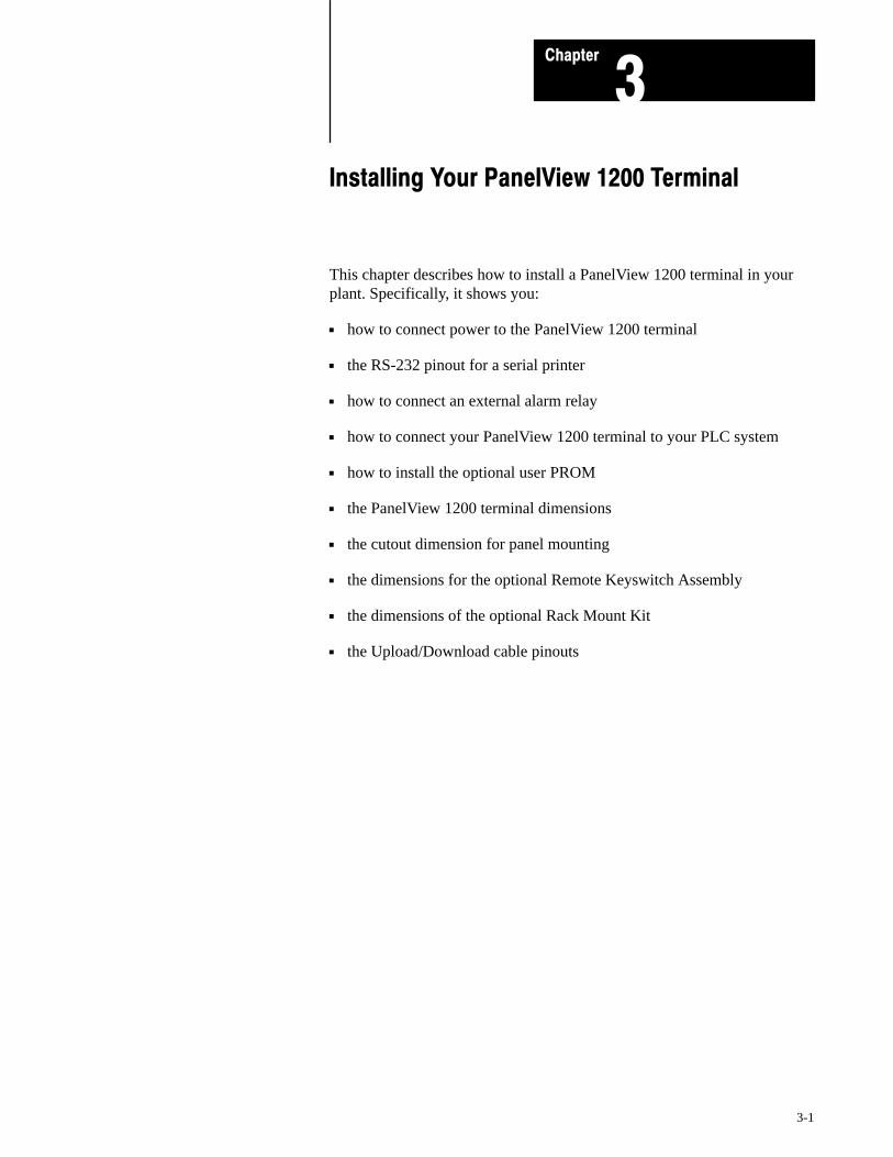
Chapter
3
3-1
Installing Your PanelView 1200 Terminal
This chapter describes how to install a PanelView 1200 terminal in yourplant. Specifically, it shows you:
how to connect power to the PanelView 1200 terminal
the RS-232 pinout for a serial printer
how to connect an external alarm relay
how to connect your PanelView 1200 terminal to your PLC system
how to install the optional user PROM
the PanelView 1200 terminal dimensions
the cutout dimension for panel mounting
the dimensions for the optional Remote Keyswitch Assembly
the dimensions of the optional Rack Mount Kit
the Upload/Download cable pinouts

Chapter 3Installing Your PanelView TerminalInstalling Your PanelView 1200 TerminalChapter 3
3-2
The following figure shows the rear panels of the PanelView 1200terminals. Note the location of the RS-232 port, the Alarm Relayconnector, the Remote I/O connector, and the power connector.
Figure 1.1PanelView 1200 Terminal Rear Panels
Contrast Control
20153
BrightnessRS-232 PortMode Select KeyswitchRemote I/O Connector
Color Back Panel Monochrome Back Panel
RS-232 PortMode Select KeyswitchRemote I/O Connector
Fuses
Power and Alarm RelayTerminal Blocks
Fuses
Power and Alarm RelayTerminal Blocks
.............. ..............
The RS�232 Port
The RS-232 port connects the PanelView 1200 terminal to thedevelopment computer for uploading and downloading application files,and connects the PanelView 1200 terminal to a serial printer.
You can also connect the optional Remote Keyswitch and RS-232 PortAssembly to the RS-232 port. This can be mounted at the front of yourrack or panel for easy access to the port and Mode Select Keyswitch.
The Upload/Download Cable connects the terminal to the developmentcomputer. If you want to connect a serial printer, you’ll have to constructyour own cable. Use the pinout in the following figure to construct thePanelView 1200 terminal end of this cable. To construct the printer end ofthe cable, consult your printer’s user manual.
The PanelView 1200 Terminal

Installing Your PanelView 1200 TerminalChapter 3
3-3
Figure 1.2RS�232 Port
20157
RXD (2)
SHIELD (1)
TXD (3)
CTS (4)
Common (7)
DTR (6)
RTS (5)
DSR(20)RS�232
SERIAL INTERFACE
DCD (8)
Pin 1Pin 14
The Alarm Relay Connector
The PanelView 1200 terminal can be used to trigger a remote alarm orwarning light under specific conditions. You would attach this remotealarm or light to the Alarm Relay (as shown in the following figure).
Figure 1.3Connecting a Remote Alarm to the Alarm Relay
20162
N/O
COM
N/C
Attention Do not use this relay for control functions of any kind.

Chapter 3Installing Your PanelView TerminalInstalling Your PanelView 1200 TerminalChapter 3
3-4
The Remote I/O Connector
The Remote I/O connector at the back of the PanelView 1200 terminalconnects the terminal to the host PLC controller via the Remote I/O link,as shown in the following figure.
If the PanelView 1200 terminal is the last device on the link, connect a 1/2watt terminating resistor across pins 1 and 2. The value of the resistordepends on the Remote I/O baud rate:
for 57.6 kilobaud and 115.2 kilobaud, use a 150� resistor (A-B part#740018-29)
for 230 kilobaud, use an 82� resistor (A-B part #740018-23)
Figure 1.4Remote I/O Connector
201632 SHIELD 1
The AC Power Connector
The PanelView 1200 terminal requires 115/230 VAC, 50/60 Hz.
Before connecting the power cable to the terminal, make sure the cable isnot carrying power. Since the PanelView 1200 terminal has no powerswitch, connecting the AC power will start the terminal if power is presentin the cable.
Attention Incorrect power wire connection can cause personalinjury or damage to equipment.
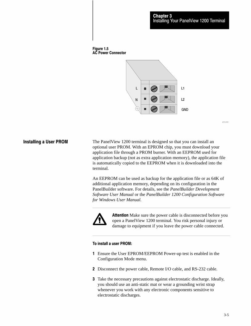
Installing Your PanelView 1200 TerminalChapter 3
3-5
Figure 1.5AC Power Connector
20164
L1
L2
GND
L
N
The PanelView 1200 terminal is designed so that you can install anoptional user PROM. With an EPROM chip, you must download yourapplication file through a PROM burner. With an EEPROM used forapplication backup (not as extra application memory), the application fileis automatically copied to the EEPROM when it is downloaded into theterminal.
An EEPROM can be used as backup for the application file or as 64K ofadditional application memory, depending on its configuration in thePanelBuilder software. For details, see the PanelBuilder DevelopmentSoftware User Manual or the PanelBuilder 1200 Configuration Softwarefor Windows User Manual.
Attention Make sure the power cable is disconnected before youopen a PanelView 1200 terminal. You risk personal injury ordamage to equipment if you leave the power cable connected.
To install a user PROM:
1 Ensure the User EPROM/EEPROM Power-up test is enabled in theConfiguration Mode menu.
2 Disconnect the power cable, Remote I/O cable, and RS-232 cable.
3 Take the necessary precautions against electrostatic discharge. Ideally,you should use an anti-static mat or wear a grounding wrist strapwhenever you work with any electronic components sensitive toelectrostatic discharges.
Installing a User PROM
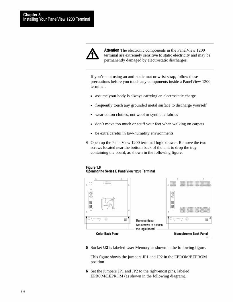
Chapter 3Installing Your PanelView TerminalInstalling Your PanelView 1200 TerminalChapter 3
3-6
Attention The electronic components in the PanelView 1200terminal are extremely sensitive to static electricity and may bepermanently damaged by electrostatic discharges.
If you’re not using an anti-static mat or wrist strap, follow theseprecautions before you touch any components inside a PanelView 1200terminal:
assume your body is always carrying an electrostatic charge
frequently touch any grounded metal surface to discharge yourself
wear cotton clothes, not wool or synthetic fabrics
don’t move too much or scuff your feet when walking on carpets
be extra careful in low-humidity environments
4 Open up the PanelView 1200 terminal logic drawer. Remove the twoscrews located near the bottom back of the unit to drop the traycontaining the board, as shown in the following figure.
Figure 1.6Opening the Series E PanelView 1200 Terminal
21171
Color Back Panel Monochrome Back Panel
Remove thesetwo screws to access the logic board.
.............. ..............
5 Socket U2 is labeled User Memory as shown in the following figure.
This figure shows the jumpers JP1 and JP2 in the EPROM/EEPROMposition.
6 Set the jumpers JP1 and JP2 to the right-most pins, labeledEPROM/EEPROM (as shown in the following diagram).
Installing Your PanelView 1200 TerminalChapter 3
3-7
Figure 1.7Series E Logic Board with Jumpers JP1 and JP2 in the EPROM/EEPROM Position
20319
Node Adapter FirmwareSystem FirmwareUser PROM
SYSTEM MEMORY
USER MEMORY
U2
JP2JP1
7 Gently ease the chip’s pins into the socket.
Attention The notch on the chip MUST be on the same end asthe notch on the socket.
Important Series C and earlier PanelView 1200 terminals use twoPROMs as user memory. Series D and E terminals require one PROM toachieve the same functionality. PanelView 1200 terminals prior to SeriesD that have had the logic board replaced may also require only onePROM depending on the revision of the logic board.
The PanelView 1200 terminal accepts either a 28-pin EPROM or a32-pin EEPROM. The 32-pin socket in the terminal is large enough toaccommodate an EEPROM, as the following figure shows. If you find itnecessary to put a 28-pin EPROM into the 32-pin socket, be sure toposition the EPROM position the EPROM as far away from the notchedend of the socket as possible.
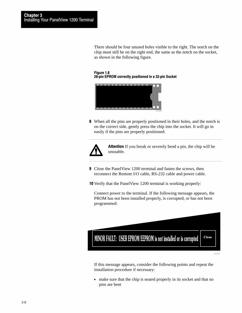
Chapter 3Installing Your PanelView TerminalInstalling Your PanelView 1200 TerminalChapter 3
3-8
There should be four unused holes visible to the right. The notch on thechip must still be on the right end, the same as the notch on the socket,as shown in the following figure.
Figure 1.828�pin EPROM correctly positioned in a 32�pin Socket
23624
8 When all the pins are properly positioned in their holes, and the notch ison the correct side, gently press the chip into the socket. It will go ineasily if the pins are properly positioned.
Attention If you break or severely bend a pin, the chip will beunusable.
9 Close the PanelView 1200 terminal and fasten the screws, thenreconnect the Remote I/O cable, RS-232 cable and power cable.
10 Verify that the PanelView 1200 terminal is working properly:
Connect power to the terminal. If the following message appears, thePROM has not been installed properly, is corrupted, or has not beenprogrammed:
20200
Clear
If this message appears, consider the following points and repeat theinstallation procedure if necessary:
make sure that the chip is seated properly in its socket and that nopins are bent

Installing Your PanelView 1200 TerminalChapter 3
3-9
make sure that the notch on the chip is on the same end as the notchon its socket
if a PROM burner was used, make sure that the instructions werecorrectly followed
if an EEPROM was used, try downloading an application file to theterminal
The following diagrams show the dimensions of the keypad and touchscreen terminals. Refer to these diagrams when mounting your terminal.
Figure 1.9Monochrome Keypad Terminal Dimensions
21167
12.40"(314.96 mm)
0.250"(6.35 mm)
11.66"(296.16 mm)
13.97"(354.84 mm)
19.00"(482.6 mm)
7 8 9
4 5 6
1 2 3• 0 -
�
� HOME �
�
CANCEL
SELECTRaise
Lower
F21
F20
F19
F18
F17
F16
F8
F15
F7
F14
F6
F13
F5
F12
F4
F11
F3
F10
F2
F9
F1
PanelView
� �
MonochromeKeypad
PanelView 1200 TerminalDimensions

Chapter 3Installing Your PanelView TerminalInstalling Your PanelView 1200 TerminalChapter 3
3-10
Figure 1.10Color Keypad Terminal Dimensions
7
21168
12.40"(314.96 mm)
0.250"(6.350 mm)
15.075"(382.91 mm)
8 9
4 5 6
1 2 3• 0 -
�
� HOME �
�
CANCEL
SELECTRaise
Lower
F21
F20
F19
F18
F17
F16
F8
F15
F7
F14
F6
F13
F5
F12
F4
F11
F3
F10
F2
F9
F1
13.97"(354.84 mm)
19.00"(482.6 mm)
0.585"(14.86 mm)
0.400"(10.16 mm)
PanelView
� �
ColorKeypad
Figure 1.11Monochrome Touch Screen Terminal Dimensions
21169
12.40"(314.96 mm)
0.680"(17.27 mm)
11.885"(301.88 mm)
13.50"(342.90 mm)
13.80"(350.52 mm)
PanelView
0.520"(13.21 mm)
MonochromeTouch Screen
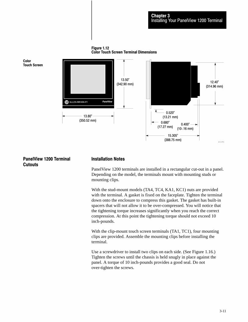
Installing Your PanelView 1200 TerminalChapter 3
3-11
Figure 1.12Color Touch Screen Terminal Dimensions
21191
0.680"(17.27 mm)
13.50"(342.90 mm)
13.80"(350.52 mm)
0.520"(13.21 mm)
15.305"(388.75 mm)
0.400"(10�.16 mm)
12.40"(314.96 mm)
PanelView
ColorTouch Screen
Installation Notes
PanelView 1200 terminals are installed in a rectangular cut-out in a panel.Depending on the model, the terminals mount with mounting studs ormounting clips.
With the stud-mount models (TA4, TC4, KA1, KC1) nuts are providedwith the terminal. A gasket is fixed on the faceplate. Tighten the terminaldown onto the enclosure to compress this gasket. The gasket has built-inspacers that will not allow it to be over-compressed. You will notice thatthe tightening torque increases significantly when you reach the correctcompression. At this point the tightening torque should not exceed 10inch-pounds.
With the clip-mount touch screen terminals (TA1, TC1), four mountingclips are provided. Assemble the mounting clips before installing theterminal.
Use a screwdriver to install two clips on each side. (See Figure 1.16.)Tighten the screws until the chassis is held snugly in place against thepanel. A torque of 10 inch-pounds provides a good seal. Do notover-tighten the screws.
PanelView 1200 TerminalCutouts
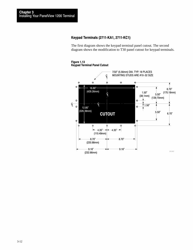
Chapter 3Installing Your PanelView TerminalInstalling Your PanelView 1200 TerminalChapter 3
3-12
Keypad Terminals (2711�KA1, 2711�KC1)
The first diagram shows the keypad terminal panel cutout. The seconddiagram shows the modification to T30 panel cutout for keypad terminals.
Figure 1.13Keypad Terminal Panel Cutout
CUTOUT
C
CL
CL
CL
1.50"(38.1mm)
5.50"(139.70mm)
1.50"
5.50"6.70"
6.70"(170.18mm)
L
4.35"(110.49mm)
4.35"
8.70"(220.98mm)
8.70"
9.16"(232.66mm)
9.16"20182
12.85"(326.39mm)
16.90"(429.26mm)
7/32" (5.56mm) DIA. TYP. 18 PLACESMOUNTING STUDS ARE #10-32 SIZE

Installing Your PanelView 1200 TerminalChapter 3
3-13
Figure 1.14Modification to T30 Panel Cutout for Keypad Terminals
CUTOUT
C
1.50"(38.1mm)
5.50"(139.70mm)
1.50"
5.50"6.70"
6.70"(170.18mm)
4.35"(110.49mm)
4.35"
8.70"(220.98mm)
8.70"
9.16"(232.66mm)
9.16"20183
12.85"(326.39mm)
16.90"(429.26mm)
CUTOUT
L
CUTOUT
CL
6.425"(163.2mm)
1.08"(27.43mm)
7/32" (5.56mm) DIA. TYP. 18 PLACESMOUNTING STUDS ARE #10-32 SIZE
6.425"
1.08"
Touch Screen Terminals (2711�TA1, TC1)
The following diagram shows the clip-mount touch screen terminal panelcutout and the touch screen terminal clip-mount.
Figure 1.15Clip Mount Touch Screen Terminal Panel Cutout
C
CL
L
23651
CUTOUT
12.55"(318.77 mm)
12.50"(317.5mm)
CL
CL
6.24"(158.49mm)
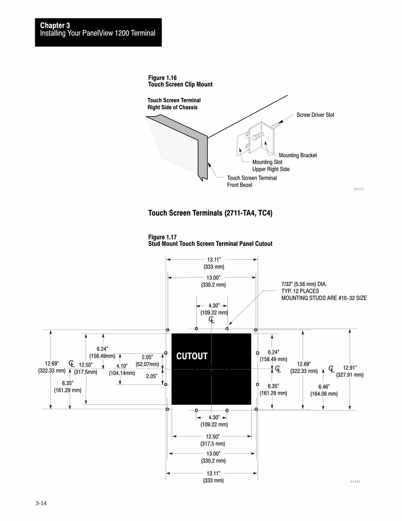
Chapter 3Installing Your PanelView TerminalInstalling Your PanelView 1200 TerminalChapter 3
3-14
Figure 1.16Touch Screen Clip Mount
20313
Mounting SlotUpper Right Side
Mounting Bracket
Screw Driver Slot
Touch Screen TerminalFront Bezel
Touch Screen TerminalRight Side of Chassis
Touch Screen Terminals (2711�TA4, TC4)
Figure 1.17Stud Mount Touch Screen Terminal Panel Cutout
C
CL
6.35"(161.29 mm)
L
4.30"(109.22 mm)
21181
CUTOUT
13.00"(330.2 mm)
12.50"(317.5 mm)
6.24"(158.49 mm)
2.05"
12.50"(317.5mm)
13.11"(333 mm)
2.05"(52.07mm)4.10"
(104.14mm)
12.69"(322.33 mm)
6.46"(164.08 mm)
12.91"(327.91 mm)
7/32" (5.56 mm) DIA.TYP. 12 PLACESMOUNTING STUDS ARE #10-32 SIZE
13.11"(333 mm)
CL
CL CL12.69"
(322.33 mm)
CL
6.35"(161.29 mm)
6.24"(158.49mm)
4.30"(109.22 mm)
13.00"(330.2 mm)

Installing Your PanelView 1200 TerminalChapter 3
3-15
You can mount your PanelView 1200 touch screen terminal in a standard19” rack. For TC1 and TA1 (clip-mount) terminals, use the optional NR1Rack Mount Kit, and for TC4 and TA4 (stud-mount) terminals, use theoptional NR2 Rack Mount Kit.
Figure 1.18NR1 19" Rack Mount Assembly for TC1 and TA1 Terminals
20229
12.60"(320.04 mm)
19.00"(482.6 mm)
3.20"(81.28 mm)
1.48"(37.6 mm)
5.48"(139.2 mm)
8.48"(215.4 mm)
12.48"(317 mm)
13.97"(354.84 mm)
.578"(14.68 mm)
.278"(7.06 mm)
.735"(18.67 mm)
.75"(19.05 mm)
C
.125"(3.18 mm)
Clip�mount
Figure 1.19NR2 19" Rack Mount Assembly for TC4 and TA4 Terminals
23650
12.60"(320.04 mm)
19.00"(482.6 mm)
3.20"(81.28 mm)
1.48"(37.6 mm)
5.48"(139.2 mm)
8.48"(215.4 mm)
12.48"(317 mm)
13.97"(354.84 mm)
.578"(14.68 mm)
.735"(18.67 mm)
.75"(19.05 mm)
.125"(3.18 mm)
.278"(7.06 mm)
Stud�mount
Optional Clip or Stud RackMount Kits

Chapter 3Installing Your PanelView TerminalInstalling Your PanelView 1200 TerminalChapter 3
3-16
The optional Remote Keyswitch Assembly is a mode select keyswitch andan RS-232 port that can be mounted on the front of an equipment panel foreasier access. For complete mounting instructions, refer to Publication2711-5.2, Remote Keyswitch and RS-232 Port Assembly for PanelViewTerminals.
The following diagram shows the Remote Keyswitch Assembly cutout.
Figure 1.20Remote Keyswitch Assembly Cutout
2.625"(66.67 mm)
20184
∅ 0.187" (4.75 mm)4 Places
∅ 3.000
(76.2 mm )
+0.025" 0.000
2.625"(66.67 mm)
+0.64 mm 0.00
The Upload/Download Cable is used to transfer an application file to orfrom a PanelView 1200 terminal. As marked, one end of the cable connectsto your development system computer’s RS-232 port. The other endconnects to the PanelView 1200 terminal’s RS-232 port.
The Upload/Download cable by itself can be connected to a computer witha 25-pin, RS-232 port (most XT computers). Both a 25- to 9-pin adapterand a specially marked short cable are provided with eachupload/download cable. You will need these adapters only for thefollowing cases:
Remote Keyswitch AssemblyDimensions
Upload/Download Cable

Installing Your PanelView 1200 TerminalChapter 3
3-17
If you have a computer that has a 9-pin RS-232 Port (most ATcomputers), connect the 25- to 9-pin adapter to the computer end of theupload/download cable.
If you are using an Allen-Bradley 6121-CBB Combo Adapter 2option card, connect the specially marked short cable to the computerend of the upload/download cable. This adapter will accommodate theslightly different pinout configuration found on this card.
Figure 1.21Upload/Download Cable (for most XT computers)
20185
25�PIN MALE (Terminal)
1
2
3
4
5
6
7
8
20
SHIELD
RXD
TXD
CTS
RTS
DTR
COM
DCD
DSR
25�PIN FEMALE(Development Sys.)
2
3
4
5
6
7
8
20
NC
TXD
RXD
RTS
CTS
DSR
COM
DCD
DTR

Chapter 3Installing Your PanelView TerminalInstalling Your PanelView 1200 TerminalChapter 3
3-18
Figure 1.2225�Pin to 9�Pin Adapter (for most AT computers)
20222
25�PIN MALE(Upload/Download Cable)
1
2
3
4
5
6
7
8
20
SHIELD
TXD
RXD
RTS
CTS
DSR
COM
DCD
DTR
9�PIN FEMALE(Development Sys.)
3
2
7
8
6
5
1
4
NC
TXD
RXD
RTS
CTS
DSR
COM
DCD
DTR
Figure 1.23Adapter Cable (for 6121 Combo Adapter 2 option card)
20221
25�PIN MALE(Upload/Download Cable)
1
2
3
4
5
6
7
8
20
SHIELD
TXD
RXD
RTS
CTS
DSR
COM
DCD
DTR
9�PIN FEMALE(Development Sys.)
2
3
4
5
6
7
8
9
NC
TXD
RXD
RTS
CTS
DSR
COM
DCD
DTR
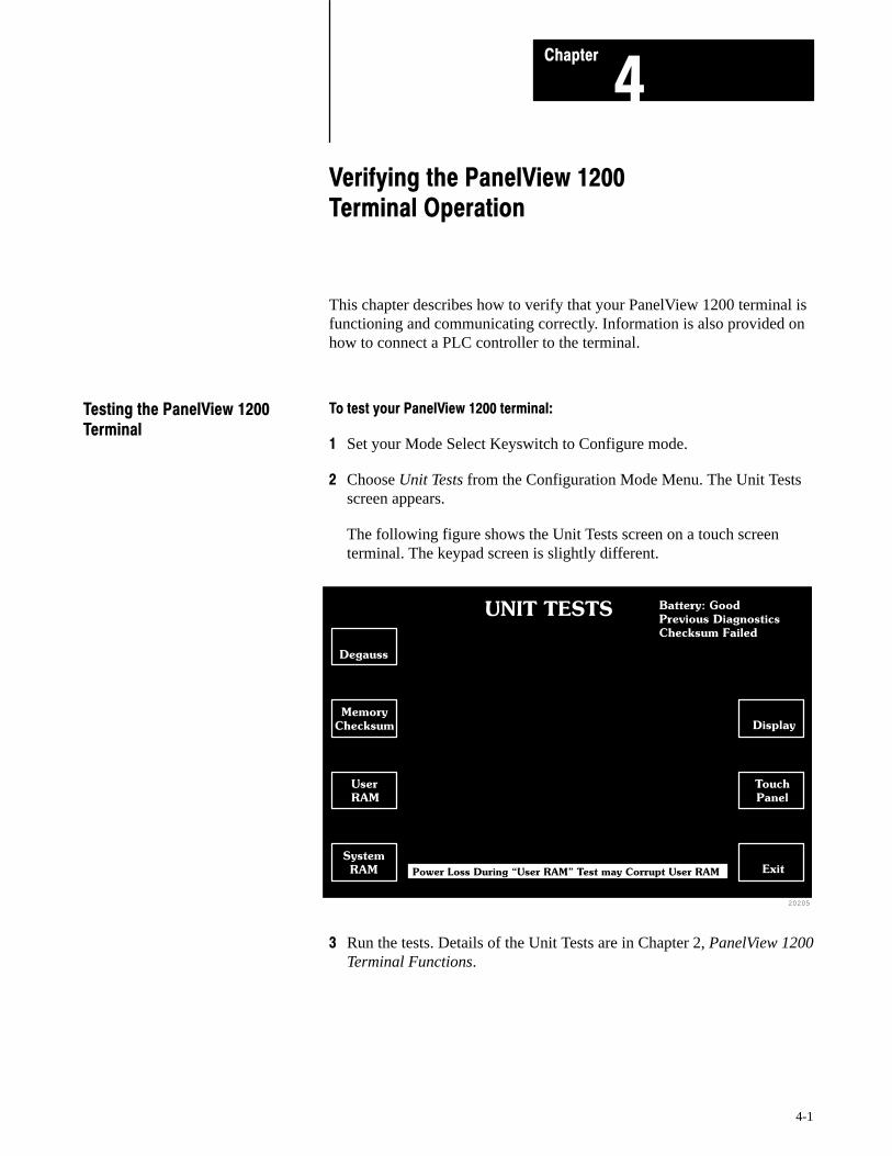
Chapter
4
4-1
Verifying the PanelView 1200 Terminal Operation
This chapter describes how to verify that your PanelView 1200 terminal isfunctioning and communicating correctly. Information is also provided onhow to connect a PLC controller to the terminal.
To test your PanelView 1200 terminal:
1 Set your Mode Select Keyswitch to Configure mode.
2 Choose Unit Tests from the Configuration Mode Menu. The Unit Testsscreen appears.
The following figure shows the Unit Tests screen on a touch screenterminal. The keypad screen is slightly different.
20205
UNIT TESTS Battery: Good
Previous Diagnostics
Checksum Failed
Memory
Checksum
Degauss
User
RAM
System
RAM Power Loss During �User RAM" Test may Corrupt User RAM
Display
Touch
Panel
Exit
3 Run the tests. Details of the Unit Tests are in Chapter 2, PanelView 1200Terminal Functions.
Testing the PanelView 1200Terminal

Verifying the PanelView 1200Chapter 4
Terminal Operation
4-2
The remainder of this chapter discusses testing your PanelView 1200terminal with an application file. If you or your developer have alreadycreated an application with PanelBuilder software, use that file. If you areinstalling a new terminal and are new to PanelBuilder software as well,you may not have an application file ready to run on the PanelView 1200terminal. If so, use the appropriate DEMO file.
Your PanelBuilder software includes demonstration files for both the touchscreen terminal (TC-DEMO) and the keypad terminal (KC-DEMO). Ifyour system does not yet include an application file of your own todownload and test, use the appropriate DEMO file for your terminal.
Matching Communications Settings
Before you can download or upload, the communication settings on thePanelView 1200 terminal and in the PanelBuilder software must be thesame. The factory settings of the PanelView 1200 terminal and thePanelBuilder software are matched. If you have not changed them, you candownload the DEMO or your other application file now.
To reset the terminal to its default settings:
1 Choose Serial Port from the Configuration Mode Menu.
2 Choose Factory Defaults.
If you need to reset the parameters in your PanelBuilder developmentcomputer, see your PanelBuilder Development Software User Manual orthe PanelBuilder 1200 Configuration Software for Windows User Manual.
Downloading the Application
Once you have matched the communication settings, you are ready tobegin downloading.
To download the application file:
1 Connect the PanelView 1200 terminal to the development computerwith the Upload/Download cable.
2 Set the PanelView 1200 terminal’s keyswitch to Configure Mode.
3 Choose Upload/Download from the terminal’s Configuration ModeMenu.
Downloading the ApplicationFile
Verifying the PanelView 1200Chapter 4
Terminal Operation
4-3
4 In the development computer, choose an application file fordownloading, and start the Download. Choose your own application fileif you have one. If not, choose KC-DEMO if you are testing a keypadterminal, TC-DEMO if you are testing a touch screen terminal.
For details on downloading an application file, see your PanelBuilderDevelopment Software User Manual, your PanelBuilder 1200Configuration Software for Windows User Manual, or your PanelView1200 Transfer Utility User Manual.
Attention Do not connect a PLC controller to the terminal. Youdo not have a functional application file, and you are not readyto monitor a PLC controller.
Set the terminal’s keyswitch to Run.
Important When the PLC controller is not connected, the terminal willdisplay a flashing message PLC communication lost . You cansafely ignore this message at this stage.
If the power-up screen for your application file appears on your terminal,your file has been successfully downloaded. (If you are downloading aDEMO file, the Main Menu will appear on the terminal.)
Try some or all of the items in your application to ensure that the variousscreens and buttons are working.
Once the screens and buttons are behaving as expected, connect aprogramming terminal to the PLC controller and monitor the PLCcontroller’s I/O Data Table.
Attention Disable all the other I/O racks or modules that couldbe affected by the PanelView 1200 terminal.
The PanelBuilder for DOS software installation includes file\PDS\2711.ACH. Download this PLC application file to your PLCcontroller if:
you are using one of the DEMO files as your application file, and
your PLC controller is a PLC-5
Running the Application File
Connecting the PLC Controller

Verifying the PanelView 1200Chapter 4
Terminal Operation
4-4
If you are using another PanelBuilder application file, you will have to useyour own PLC application program for whatever PLC controller you areusing.
At this stage, connect the PanelView 1200 terminal to the PLC controller,but don’t have the PLC controller control any machines or processes.
Refer to your scanner and PLC controller manuals for information on howto create scan lists that include all rack assignments for the PanelView1200 terminal.
Once all PLC controlled machines and processes have been disabled, youcan put both the PLC controller and PanelView 1200 terminal into Runmode, if you haven’t already done so.
Run through each screen in the application file, just as you would test anew control panel’s inputs and outputs before starting up a new controlsystem. Use the programming terminal to monitor what happens inside thePLC controller as you use each object, and then change the values withinthe PLC controller to see how the PanelView 1200 terminal responds.
Switch the PanelView 1200 terminal to Configure mode and back to Runmode. You should also remove and re-apply power to the PLC controllerseparately, and to the entire control system to ensure that the systemre-initializes as expected.
Testing Retentive Objects
Observe each object carefully if you are using any retentive input objects.Switch the terminal off and on again, and switch it to Configuration modeand back to Run mode. Watch the input addresses for each retentive objectto ensure that the values are initialized so that the the program will respondsafely.
Once you’ve checked all PLC values and determined that all objects,windows, and PLC controlled functions communicate properly with thePLC, you’re ready to set both the PLC and the terminal into Run mode andtest your application file in action.
Testing the Whole System
Verifying the PanelView 1200Chapter 4
Terminal Operation
4-5
Attention If the PLC program can control any specific machineaction or process that could result in unsafe or critical operation,temporarily disable these specific operations. Keep people at asafe distance from any PLC controlled machine. Finally, makesure emergency stop buttons are easily accessible during controlsystem testing.
Step through each screen to make sure that valid states and values aredisplayed. Test each object one at a time to ensure that the PLC systemresponds as expected.
Power down, then power up the PanelView 1200 terminal, and switch theterminal to Configure mode and back to Run mode. You should alsoremove and re-apply power to the PLC separately, and to the entire controlsystem to ensure that the system re-initializes as expected.
Your PanelView 1200 terminal is now ready for use.

Chapter
5
5-1
Maintaining Your PanelView 1200 Terminal
Follow the instructions below to keep your PanelView 1200 terminalfunctioning at top efficiency.
Cleaning
Cleaning the Touch Screen
To clean the touch screen, use ethyl alcohol (ethanol) on a cotton gauzepad. This is more efficient than isopropyl alcohol, (which leaves a slightresidue upon first application), and safer than MEK (methyl ethyl ketone).MEK is harmless to the touch screen, but repeated applications willdiscolor the bezel if the paint surface is broken or scratched.
Cleaning the Keypad
To clean the front of the keypad terminal, use a 50% solution of alcohol(ethanol or isopropyl) in water on a cotton gauze pad or soft cotton cloth.Mild soap or detergent and warm water is also permissible, but avoidabrasive cleaners.
Cleaning the Enclosure
Use a 50% solution of alcohol (ethanol or isopropyl) in water on a cottongauze pad or soft cotton cloth to clean the enclosure.
Important The solvent should be applied only to the cloth, not directly tothe enclosure.
Important The introduction of fluid into the enclosure could damageinternal components.
CRT Intensity
The lower the intensity at which the CRT operates, the longer its life. Youcan control the intensity of your screen with the brightness control on theback of a monochrome unit, and with the color contrast control on the backof a color unit.
Maintaining Your PanelView1200 Terminal

Maintaining Your PanelView 1200Chapter 5
Terminal
5-2
Changing the Filter on Color Units
Clean the filter on your color terminal whenever it appears to be in dangerof clogging up. Remove the filter cover from the back of the terminal bypopping it free of its plastic side clips. Remove the filter and clean it by:
removing the dust with a vacuum cleaner
washing with warm water and soap. Be sure the filter is dry before youreplace it.
The filter itself is made of flame-retardant urethane foam 0.13” (3.3mm)thick, and measures 3.64” by 3.54” (92.5mm by 89.9mm). If your filtershould become unusable, replace it with part number 09362-M/45 fromHitachi or Qualtek Electronics.
Screen Saver
The screen saver preserves the life of the PanelView 1200 terminal screenby blanking the screen when no buttons have been pressed for auser-definable period of time.
Choose Screen Saver from the Configuration Mode menu to display theScreen Saver Timeout screen. Here you set the amount of time that shouldpass without screen activity before the screen blanks. Elapsed time canrange from 1 to 999 minutes. A setting of 0 (zero) disables the screensaver.
Mode changes, PLC generated Alarm Messages, Information Messages,screen requests, or terminal fault messages also turn off the screen saver.
Degauss
If an external magnetic field (such as an electric motor starting up) occursnear a color terminal, the CRT may retain some residual magnetic effect,which in turn may affect the clarity of the display. Degaussing removesany such residual magnetism by totally demagnetizing the CRT. Automaticdegauss occurs each time AC power is re-applied to the terminal and atmidnight (according to the PanelView 1200 terminal system clock) daily.
You can also degauss the color terminal manually by choosing Unit Testsfrom the Configuration Menu. Then choose Degauss from the Unit Testsscreen. See Chapter 2, PanelView 1200 Terminal Functions, for moreinformation.
Maintaining Your PanelView 1200Chapter 5
Terminal
5-3
When the color terminal degausses, there is a 6.5 amp surge. The surgelasts less than 400 milliseconds. If your PanelView 1200 terminal ispowered by an isolated power source, be sure the line transformer canhandle this surge.
Strong Magnetic Fields
Since the PanelView 1200 terminal display contains a CRT (cathode raytube), the presence of strong magnetic fields near the terminal will distortthe image on the screen. Magnetic fields stronger than 80 milligauss at thefront surface of the terminal should be avoided.

Appendix
A
A-1
Specifications
Specifications in this section apply to all of the following products unlessindicated otherwise:
2711-KA1 Series E Keypad Terminals w/Amber CRT
2711-KC1 Series E Keypad Terminals w/Color CRT
2711-TA1 Series E Touch Screen Terminals w/Amber CRT, clip mount
2711-TC1 Series E Touch Screen Terminals w/Color CRT, clip mount
2711-TA4 Series E Touch Screen Terminals w/Amber CRT, stud mount
2711-TC4 Series E Touch Screen Terminals w/Color CRT, stud mount
Standards Organizations Approvals
UL listed, Industrial Control Equipment (UL 508)
CSA certified, standard 22.2 No. 142
Design Standards Complied With
IP65
IEC 348, IEC 435
VDE-0871 Class A, VDE-0805, VDE-0110
FCC Part 15, subpart J, Class A
PanelView 1200 terminals are designed to meet the following NEMAStandards when mounted in like enclosures.
Keypad Terminals
NEMA 4X (Indoor Use Only), NEMA 12, and NEMA 13
Specifications
Design Certifications,Standards and Compliances

SpecificationsAppendix A
A-2
Touch Screen Terminals
Stud-mount: NEMA 4X (Indoor Use Only), NEMA 12, and NEMA 13Clip-mount: NEMA 12
Keypad Terminal w/Amber CRT 25.0 lbs (11.34 kg)
Keypad Terminal w/Color CRT 35.75 lbs (16.26 kg)
Touch Screen Terminal w/Amber CRT 23.25 lbs (10.55 kg)
Touch Screen Terminal w/Color CRT 32.5 lbs (14.74 kg)
These weights do not include any shipping materials used to packagePanelView 1200 terminals.
Keypad Terminals
Key Panel: black anodized sheet aluminum with continuous hard-coated scratch-resistant polyester surface
Keys: sealed stainless steel dome membrane switches with tactilefeedback and an actuation force of 16 oz.(0.455 kg), mounted on the key panel’s anodized aluminum backer plate. Keys are rated for 2,000,000 presses.
Window: Continuous water-clear polyester over chemically strengthened glass
Custom legends can be inserted in the 21 user–configurable function keysand the Select, Cancel, Raise and Lower keys.
Touch Screen Terminals
Membrane: Water-clear, hardcoated, scratch-resistant polyester, over chemically strengthened glass
Bezel: Cast aluminum with a black powder coating
Touch cell actuation force: From 2.5 to 3 oz (71 to 85 grams)
Terminal Weights
Front Panel Design

SpecificationsAppendix A
A-3
Touch Cell Format
matrix of 120 touch cells (10 across by 12 high)
each touch cell is 2 characters high by 8 characters wide
user can configure/group cells to any size buttons
Touch cells are rated for 1,000,000 presses.
The following tables provide details of the display specifications.
Display Format 24 Rows x 80 Columns (normal size characters)
Character Cell Pixel Format 8 wide x 10 high
Display Alignment User�configurable, stored in non�volatile memory, 12 character
horizontal range, 2.4 character vertical range
Display Intensity Low to high range adjustment on back of unit
Screen Saver User�configurable, 1�999 minute timeout
Display Size 12" Diagonal
Color Unit Display Attributes
You select 8 from a palette of 16 colors.
ÁÁÁÁÁÁÁÁÁÁÁÁÁÁÁÁ
Black ÁÁÁÁÁÁÁÁÁÁÁÁÁÁÁÁ
Grey
ÁÁÁÁÁÁÁÁÁÁÁÁÁÁÁÁ
White ÁÁÁÁÁÁÁÁÁÁÁÁÁÁÁÁ
Bright White
ÁÁÁÁÁÁÁÁÁÁÁÁÁÁÁÁ
Red ÁÁÁÁÁÁÁÁÁÁÁÁÁÁÁÁ
Bright Red
ÁÁÁÁÁÁÁÁÁÁÁÁÁÁÁÁ
Blue ÁÁÁÁÁÁÁÁÁÁÁÁÁÁÁÁ
Bright Blue
ÁÁÁÁÁÁÁÁÁÁÁÁÁÁÁÁ
Green ÁÁÁÁÁÁÁÁÁÁÁÁÁÁÁÁ
Bright Green
ÁÁÁÁÁÁÁÁÁÁÁÁÁÁÁÁ
Magenta ÁÁÁÁÁÁÁÁÁÁÁÁÁÁÁÁ
Bright Magenta
ÁÁÁÁÁÁÁÁÁÁÁÁÁÁÁÁ
Cyan ÁÁÁÁÁÁÁÁÁÁÁÁÁÁÁÁ
Bright Cyan
ÁÁÁÁÁÁÁÁÁÁÁÁÁÁÁÁ
Yellow ÁÁÁÁÁÁÁÁÁÁÁÁÁÁÁÁ
Bright Yellow
Foreground/background color for individual screen objects and functionscan be assigned any of the above. However, some colors do not appearexactly the same on a PanelView 1200 terminal as they do on thedevelopment computer. You may find, as well, that white appears to belight grey and grey appears to be black if they are contrasted with certainother colors. For these reasons, you may find that you achieve the bestresults if you reserve the colors in the right hand column for foregroundcolors only.
CRT Display

SpecificationsAppendix A
A-4
Other attributes include blink and underline. Character sizes include 1x1(standard), 1x2 (double width), 2x1 (double height) and 2x2 (doubleheight, double width).
Automatic degauss occurs each time AC power is re-applied to the unit andat midnight (according to the PanelView 1200 terminal system clock)daily.
Monochrome Unit Display Attributes
Foreground Color: Amber
Background Color: Black
Other attributes include reverse video, high intensity, blink and underline.Character sizes include 1x1 (standard), 1x2 (double width), 2x1 (doubleheight) and 2x2 (double height, double width).
These are the parameters of the PLC Remote I/O Communications:
Allen-Bradley PLC via Allen-Bradley 1771 Remote I/O Link
Remote I/O baud rate: 57.6/115.2/230.4 kilobaud
max I/O cable distance: 10,000 ft. (57.6 kilobaud) 5,000 ft. (115.2 kilobaud) 2,500 ft. (230.4 kilobaud)
terminal can emulate: from 1/4 to 8 full Remote I/O Racks
rack sizes:1/4, 1/2, 3/4, or Full (any starting module group)
total discrete I/O possible: 1024 Input and 1024 Output bits, or 64 PLCInput Words and 64 PLC Output Words
up to 5 block transfer read and 5 block transfer write files can beconfigured, with up to 32 words for each file
total Block Transfer possible: 2560 Inputs and 2560 Outputs or 160 PLCInput Words and 160 PLC Output Words
application files can be uploaded and downloaded via the PLC-5Pass-Through feature
PLC Remote I/OCommunications

SpecificationsAppendix A
A-5
This RS-232 port can either be connected to the development system andused to upload/download application files, or it can connected to a printerand used to print screen images, reports, or alarm messages. You canassign separate port settings for each of these purposes. The applicable portsettings are used automatically.
The following table lists the port settings.
Baud Rates 300, 600, 1200, 2400, 4800, 9600, 19.2 kilobaud
Parity Types Odd, Even, None
Stop Bits 1, 2
Data Bits 7, 8
Handshake Hardware, Software (X�ON, X�OFF), None
Auto Line Feed* Off, On
Auto Form Feed* Off, On
*Printer onlythese two parameters cannot be turned On for the serial port.
The factory defaults are the same as the default settings that thedevelopment software will apply to the selected RS-232 port on yourdevelopment system, so you normally shouldn’t need to change them. Thefactory defaults are as follows:
Port Parameters Upload/Download Printer
Baud Rates 9600 9600
Parity Types None None
Stop Bits 1 1
Data Bits 8 8
Handshake Hardware Software
Auto Line Feed Off (not configurable) On
Auto Form Feed Off (not configurable) On
Refer to the following table for information on AC power.
Power Supply Type Switching
Range 90-132, 180-264 VACautomatic setting by the PanelView 1200 terminal to matchavailable power supply
Frequency Range 47-63 Hz
Power Consumption Color Terminal 80 W
Monochrome terminal 50 W
While the color terminal degausses, there is a 6.5 amp surge. The surgelasts less than 400 milliseconds.
Serial Communications Port
AC Power
SpecificationsAppendix A
A-6
one for each AC line
accepts either US or European fuse types
user-accessible at rear of terminal
US fuse: BUSS AGC-3, 3 amps, 250 VAC, 1/4” X 1-1/4”
European fuse: BUSS GDB-3, 3 AMPS, 250 VAC, 5 mm x 20 mm
PanelView 1200 terminals support two character sets:
the IBM character set for the keyboard characters, lines, boxes, etc.
another set containing additional characters that allow the terminal todisplay objects such as pixel resolution bar graphs and ISA symbols. Toview the extended character set, refer to the appropriate appendix inyour PanelBuilder Development Software User Manual, orPanelBuilder 1200 Configuration Software for Windows User Manual.
The terminal supports 64K of standard user memory in battery-backedRAM.
You can install an additional EPROM for application file back-up. You caninstall an additional EEPROM for either application file back-up or for64K of additional application RAM, (bringing the total available RAM to128K). When the EEPROM is used as additional application RAM, itcannot be used as application file back-up.
RAM tests can be initiated in the terminal’s Unit Tests screen inConfiguration mode.
Memory Checksum tests can be initiated in the terminal’s Unit Testsscreen in Configuration mode, and are automatically executed duringterminal power-up as well.
Form-C Contact
250 VAC Max, 8 Amp Continuous
30 VDC Max, 8 Amp Continuous
Minimum Voltage: 1 VDC
Minimum Current: 1 milliamp DC
Fuses
Character Set
User Memory
Alarm Relay
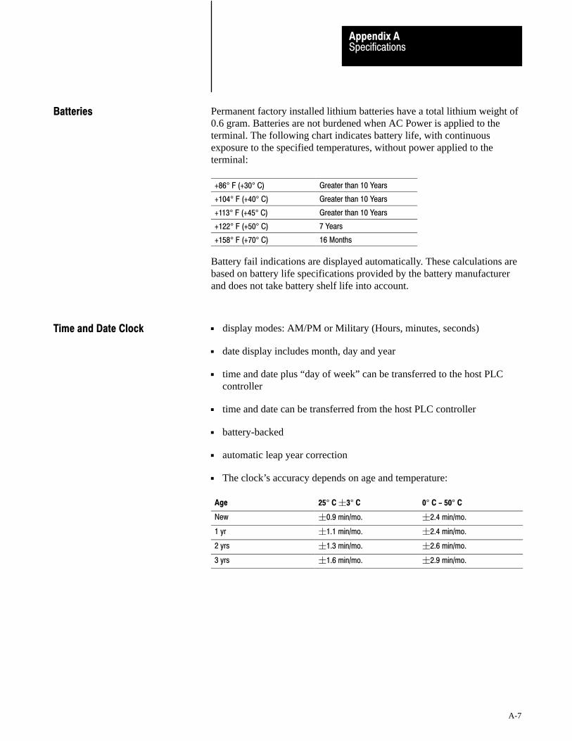
SpecificationsAppendix A
A-7
Permanent factory installed lithium batteries have a total lithium weight of0.6 gram. Batteries are not burdened when AC Power is applied to theterminal. The following chart indicates battery life, with continuousexposure to the specified temperatures, without power applied to theterminal:
ÁÁÁÁÁÁÁÁÁÁÁÁÁÁÁÁ
+86° F (+30° C) ÁÁÁÁÁÁÁÁÁÁÁÁÁÁÁÁ
Greater than 10 Years
ÁÁÁÁÁÁÁÁÁÁÁÁÁÁÁÁ
+104° F (+40° C) ÁÁÁÁÁÁÁÁÁÁÁÁÁÁÁÁ
Greater than 10 Years
ÁÁÁÁÁÁÁÁÁÁÁÁÁÁÁÁ
+113° F (+45° C) ÁÁÁÁÁÁÁÁÁÁÁÁÁÁÁÁ
Greater than 10 Years
ÁÁÁÁÁÁÁÁÁÁÁÁÁÁÁÁ
+122° F (+50° C) ÁÁÁÁÁÁÁÁÁÁÁÁÁÁÁÁ
7 Years
ÁÁÁÁÁÁÁÁÁÁÁÁÁÁÁÁ
+158° F (+70° C) ÁÁÁÁÁÁÁÁÁÁÁÁÁÁÁÁ
16 Months
Battery fail indications are displayed automatically. These calculations arebased on battery life specifications provided by the battery manufacturerand does not take battery shelf life into account.
display modes: AM/PM or Military (Hours, minutes, seconds)
date display includes month, day and year
time and date plus “day of week” can be transferred to the host PLCcontroller
time and date can be transferred from the host PLC controller
battery-backed
automatic leap year correction
The clock’s accuracy depends on age and temperature:
Age 25° C �3° C 0° C - 50° C
New �0.9 min/mo. �2.4 min/mo.
1 yr �1.1 min/mo. �2.4 min/mo.
2 yrs �1.3 min/mo. �2.6 min/mo.
3 yrs �1.6 min/mo. �2.9 min/mo.
Batteries
Time and Date Clock
SpecificationsAppendix A
A-8
Ambient Operating Temperature Limits
Maximum: +50° C (+122° F).
Minimum : 0° C (+32° F).
Storage Temperature Limits
Minimum: -40° C (-40° F)
Maximum: +70° C (+158° F)
Humidity
Relative operating humidity (non-condensing)
0°to +30° C (+32°to +86° F) 95% humidity
+30°to +40° C (+86° to +104° F) 75% humidity
+40° to +50° C (+104° to +122° F) 40% humidity
Relative non-operating humidity (non-condensing):
-40° to +70° C (-40° to +158° F) 95% humidity
Maximum Altitude
non-operating: 40,000 ft
operating: 10,000 ft
Monochrome Terminals
154 BTU/hour maximum
95 BTU/hour typical
Color Terminals
246 BTU/hour maximum
184 BTU/hour typical
Temperature, Humidity, andHigh Altitude
Heat Generation

SpecificationsAppendix A
A-9
Shock Amplitudes
operating 15 G (Peak Acceleration)
non-operating 30 G (Peak Acceleration)
Vibration Amplitudes for Operating Units
Frequency range: 5 to 2000 Hz
5 to 57 Hz: .006” peak-to-peak displacement
58 to 2000 Hz: 1.0 G peak acceleration
Vibration Amplitudes for Non�Operating Units
Frequency range: 5 to 2000 Hz
5 to 57 Hz: .015” peak-to-peak displacement
58 to 2000 Hz: 2.5 G peak acceleration
Shock and Vibration

Appendix
B
B-1
Troubleshooting
This appendix describes how to diagnose and solve problems regarding theoperation of a PanelView 1200 terminal.
To view the I/O racks and block transfer settings as defined inPanelBuilder software, select Rack Assignments from the PanelView 1200terminal’s Configuration Mode Menu.
The following table lists the most common major fault messages that canappear on a PanelView 1200 terminal.
Major Fault Message Cause What to do
Stuck Cell detected or Stuck Button detected. A touch cell or Keypad button has beendepressed for longer than the Stuck ButtonTimeout setting allows.
Restart the terminal. If this problem occursrepeatedly due to an operator holding the buttondown for too long, increase the Stuck ButtonTimeout setting in the Configuration menu.If a button or cell is permanently stuck, call yourA�B representative.
Watchdog Test Failed. Unit is disabled. Watchdog circuit is unable to reset the machine. Servicing by Allen�Bradley is required.
System ROM corrupted. Unit is disabled. The ROM containing the system firmware isdefective.
Servicing by Allen�Bradley is required.
RAM TEST failed. Unit is disabled. The non�backed�up RAM used by the terminalfirmware is defective.
Servicing by Allen�Bradley is required.
Video hardware initialization failed. Unit isdisabled.
There is a video hardware problem. Servicing by Allen�Bradley is required.
Mismatched application file. Unit is disabled. 1.) The application file is for the wrong type, i.e.,a Keypad file on a Touch Screen terminal.
2.) The jumper settings are wrong.
1.) Download an application file of the appropriate type.
2.) Check the setting of JP5:FB = KeypadTS = Touch Screen
Failed to configure the Comm card. Unit isdisabled.
The Communication circuitry is faulty. Servicing by Allen�Bradley is required.
Failed to stop PLC communication. Unit isdisabled.
The Communication circuitry is faulty. Servicing by Allen�Bradley is required.
Application file corrupted. The system has not stored the file correctly. Download the file again or install new EEPROM.
Verifying ConfigurationSettings
PanelView 1200 Major FaultError Messages

TroubleshootingAppendix B
B-2
The following table lists the most common minor fault messages that canappear on a PanelView 1200 terminal.
Minor Fault Message Cause What to do
Retentive data initialization failed. There is no valid application file. Go off�line and download the file again.
Audio hardware initialization failed. There is an audio hardware problem. Servicing by Allen�Bradley is required.
Terminal can't keep up with activity. Too much incoming data. The operator should stop all input until thePanelView 1200 terminal can process data.
Invalid Powerup Screen. Powerup screen does not exist or is faulty. Reassign the Powerup Screen or check theconfiguration data in the PanelBuilderapplication file.
ÁÁÁÁÁÁÁÁÁÁÁÁÁÁÁÁÁÁÁÁÁÁÁÁÁÁÁÁÁÁÁÁÁÁÁÁÁÁÁÁÁÁÁÁÁÁÁÁÁÁÁÁÁÁÁÁÁÁÁÁÁÁÁÁÁÁÁÁÁÁÁÁÁÁÁÁÁÁÁÁÁÁÁÁÁÁÁÁÁÁÁÁÁÁÁÁ
User EPROM/EEPROM is not installed or iscorrupted.
ÁÁÁÁÁÁÁÁÁÁÁÁÁÁÁÁÁÁÁÁÁÁÁÁÁÁÁÁÁÁÁÁÁÁÁÁÁÁÁÁÁÁÁÁÁÁÁÁÁÁÁÁÁÁÁÁÁÁÁÁÁÁÁÁÁÁÁÁÁÁÁÁÁÁÁÁÁÁÁÁÁÁÁÁÁÁÁÁÁÁÁÁÁÁÁÁ
Optional EPROM or EEPROM was not found oris faulty.
ÁÁÁÁÁÁÁÁÁÁÁÁÁÁÁÁÁÁÁÁÁÁÁÁÁÁÁÁÁÁÁÁÁÁÁÁÁÁÁÁÁÁÁÁÁÁÁÁÁÁÁÁÁÁÁÁÁÁÁÁÁÁÁÁÁÁÁÁÁÁÁÁÁÁÁÁÁÁÁÁÁÁÁÁÁÁÁÁÁÁÁÁÁÁÁÁ
If no user EPROM or EEPROM is installed,ignore this message. You can disable the testand the message in the Configuration ModeMenu.If a user EPROM or EEPROM is installed, checkPROM jumpers, look for bent pins, check forproper PROM notch alignment, and verify thatthere is a valid program in the PROM. If thePROM is an EEPROM, try downloading theapplication file again.
ÁÁÁÁÁÁÁÁÁÁÁÁÁÁÁÁÁÁÁÁÁÁÁÁÁÁÁÁÁÁÁÁÁÁÁÁ
Battery test failed. User RAM will be lost onpower down.
ÁÁÁÁÁÁÁÁÁÁÁÁÁÁÁÁÁÁÁÁÁÁÁÁÁÁÁÁÁÁÁÁÁÁÁÁ
The battery for application file memory is dead.ÁÁÁÁÁÁÁÁÁÁÁÁÁÁÁÁÁÁÁÁÁÁÁÁÁÁÁÁÁÁÁÁÁÁÁÁ
Upload the application file and save it on disk.Servicing by Allen�Bradley is required.
ÁÁÁÁÁÁÁÁÁÁÁÁÁÁÁÁÁÁÁÁÁÁÁÁ
Communication Self Test failed. ÁÁÁÁÁÁÁÁÁÁÁÁÁÁÁÁÁÁÁÁÁÁÁÁ
The communication card is defective or notinstalled.
ÁÁÁÁÁÁÁÁÁÁÁÁÁÁÁÁÁÁÁÁÁÁÁÁ
Servicing by Allen�Bradley is required.
ÁÁÁÁÁÁÁÁÁÁÁÁÁÁÁÁÁÁÁÁÁÁÁÁÁÁÁÁÁÁÁÁÁÁÁÁ
Invalid Screen.ÁÁÁÁÁÁÁÁÁÁÁÁÁÁÁÁÁÁÁÁÁÁÁÁÁÁÁÁÁÁÁÁÁÁÁÁ
The PLC has selected a non�existent screennumber.
ÁÁÁÁÁÁÁÁÁÁÁÁÁÁÁÁÁÁÁÁÁÁÁÁÁÁÁÁÁÁÁÁÁÁÁÁ
Reprogram the PLC or the application file.
ÁÁÁÁÁÁÁÁÁÁÁÁÁÁÁÁÁÁÁÁÁÁÁÁÁÁÁÁÁÁÁÁÁÁÁÁ
Unable to write downloaded data to theEEPROM.
ÁÁÁÁÁÁÁÁÁÁÁÁÁÁÁÁÁÁÁÁÁÁÁÁÁÁÁÁÁÁÁÁÁÁÁÁ
The EEPROM is faulty or user memoryconfiguration jumpers are set incorrectly.
ÁÁÁÁÁÁÁÁÁÁÁÁÁÁÁÁÁÁÁÁÁÁÁÁÁÁÁÁÁÁÁÁÁÁÁÁ
Check the EEPROM, and verify user memoryconfiguration jumper settings.
ÁÁÁÁÁÁÁÁÁÁÁÁÁÁÁÁÁÁÁÁÁÁÁÁÁÁÁÁÁÁÁÁÁÁÁÁÁÁÁÁÁÁÁÁÁÁÁÁÁÁÁÁÁÁÁÁÁÁÁÁ
Value Out Of Range. ÁÁÁÁÁÁÁÁÁÁÁÁÁÁÁÁÁÁÁÁÁÁÁÁÁÁÁÁÁÁÁÁÁÁÁÁÁÁÁÁÁÁÁÁÁÁÁÁÁÁÁÁÁÁÁÁÁÁÁÁ
Address not sufficient for data transfer.
Current screen number transferred to PLC is notsufficient.
Numeric entry or display address length isinsufficient for data.
ÁÁÁÁÁÁÁÁÁÁÁÁÁÁÁÁÁÁÁÁÁÁÁÁÁÁÁÁÁÁÁÁÁÁÁÁÁÁÁÁÁÁÁÁÁÁÁÁÁÁÁÁÁÁÁÁÁÁÁÁ
Increase bit length of address so it's largeenough for screen transfer, including AlarmHistory and Alarm Status screens.
Increase address length for data.
PLC currently controls screen change PLC controller has control of screen change. Disable PLC Controlled Screen Change.Set PLC Controlled Screen Change value to 0.
No screen changeHold Time in effect or noPLC Handshake
Operator is trying to change screens while abutton's hold time is still in effect or before anactivated Latched Push Button has received ahandshake.
Wait until hold time is finished or Latchedhandshake is received before trying to changescreens.
PanelView 1200 Minor FaultError Messages
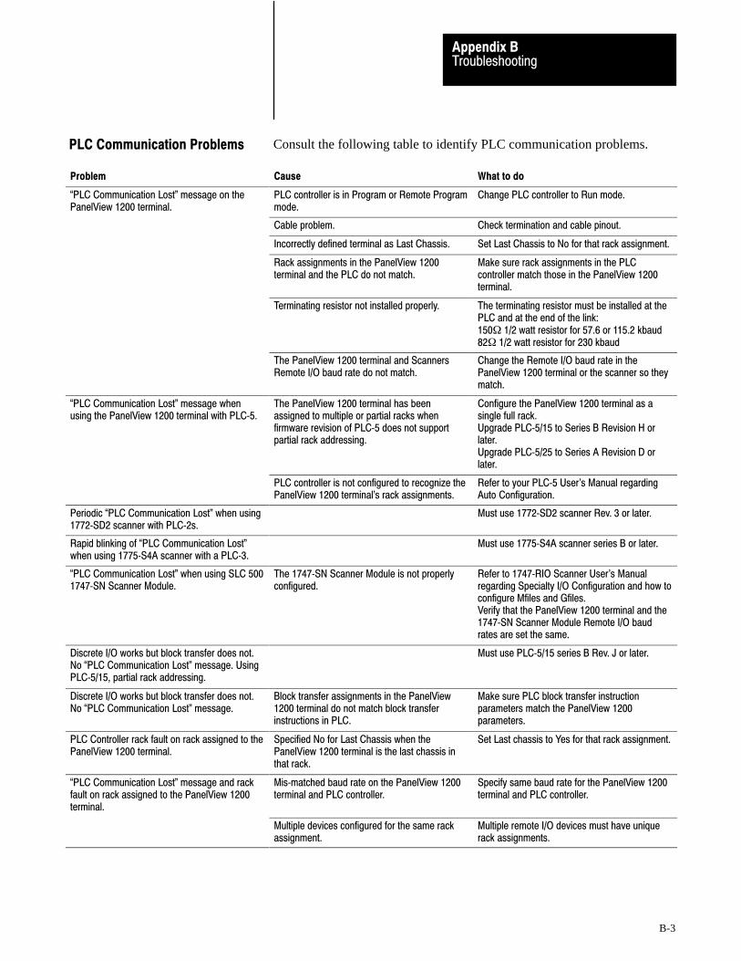
TroubleshootingAppendix B
B-3
Consult the following table to identify PLC communication problems.
Problem Cause What to doÁÁÁÁÁÁÁÁÁÁÁÁÁÁÁÁÁÁÁÁÁÁÁÁÁÁÁÁÁÁÁÁÁÁÁÁ
�PLC Communication Lost" message on thePanelView 1200 terminal.
ÁÁÁÁÁÁÁÁÁÁÁÁÁÁÁÁÁÁÁÁÁÁÁÁÁÁÁÁÁÁÁÁÁÁÁÁ
PLC controller is in Program or Remote Programmode.
ÁÁÁÁÁÁÁÁÁÁÁÁÁÁÁÁÁÁÁÁÁÁÁÁÁÁÁÁÁÁÁÁÁÁÁÁ
Change PLC controller to Run mode.
Cable problem. Check termination and cable pinout.
ÁÁÁÁÁÁÁÁÁÁÁÁÁÁÁÁÁÁÁÁÁÁÁÁ
ÁÁÁÁÁÁÁÁÁÁÁÁÁÁÁÁÁÁÁÁÁÁÁÁ
Incorrectly defined terminal as Last Chassis. ÁÁÁÁÁÁÁÁÁÁÁÁÁÁÁÁÁÁÁÁÁÁÁÁ
Set Last Chassis to No for that rack assignment.
ÁÁÁÁÁÁÁÁÁÁÁÁÁÁÁÁÁÁÁÁÁÁÁÁÁÁÁÁÁÁÁÁÁÁÁÁ
ÁÁÁÁÁÁÁÁÁÁÁÁÁÁÁÁÁÁÁÁÁÁÁÁÁÁÁÁÁÁÁÁÁÁÁÁ
Rack assignments in the PanelView 1200terminal and the PLC do not match.
ÁÁÁÁÁÁÁÁÁÁÁÁÁÁÁÁÁÁÁÁÁÁÁÁÁÁÁÁÁÁÁÁÁÁÁÁ
Make sure rack assignments in the PLCcontroller match those in the PanelView 1200terminal.ÁÁÁÁÁÁÁÁÁÁÁÁ
ÁÁÁÁÁÁÁÁÁÁÁÁÁÁÁÁÁÁÁÁÁÁÁÁÁÁÁÁÁÁÁÁÁÁÁÁ
ÁÁÁÁÁÁÁÁÁÁÁÁÁÁÁÁÁÁÁÁÁÁÁÁÁÁÁÁÁÁÁÁÁÁÁÁÁÁÁÁÁÁÁÁÁÁÁÁ
Terminating resistor not installed properly.ÁÁÁÁÁÁÁÁÁÁÁÁÁÁÁÁÁÁÁÁÁÁÁÁÁÁÁÁÁÁÁÁÁÁÁÁÁÁÁÁÁÁÁÁÁÁÁÁ
The terminating resistor must be installed at thePLC and at the end of the link:150� 1/2 watt resistor for 57.6 or 115.2 kbaud82� 1/2 watt resistor for 230 kbaud
The PanelView 1200 terminal and ScannersRemote I/O baud rate do not match.
Change the Remote I/O baud rate in thePanelView 1200 terminal or the scanner so theymatch.
�PLC Communication Lost" message whenusing the PanelView 1200 terminal with PLC�5.
The PanelView 1200 terminal has beenassigned to multiple or partial racks whenfirmware revision of PLC�5 does not supportpartial rack addressing.
Configure the PanelView 1200 terminal as asingle full rack.Upgrade PLC�5/15 to Series B Revision H orlater.Upgrade PLC�5/25 to Series A Revision D orlater.
PLC controller is not configured to recognize thePanelView 1200 terminal's rack assignments.
Refer to your PLC�5 User's Manual regardingAuto Configuration.
ÁÁÁÁÁÁÁÁÁÁÁÁÁÁÁÁÁÁÁÁÁÁÁÁ
Periodic �PLC Communication Lost" when using1772�SD2 scanner with PLC�2s.
ÁÁÁÁÁÁÁÁÁÁÁÁÁÁÁÁÁÁÁÁÁÁÁÁ
ÁÁÁÁÁÁÁÁÁÁÁÁÁÁÁÁÁÁÁÁÁÁÁÁ
Must use 1772�SD2 scanner Rev. 3 or later.
ÁÁÁÁÁÁÁÁÁÁÁÁÁÁÁÁÁÁÁÁÁÁÁÁÁÁÁÁÁÁÁÁÁÁÁÁ
Rapid blinking of �PLC Communication Lost"when using 1775�S4A scanner with a PLC�3.
ÁÁÁÁÁÁÁÁÁÁÁÁÁÁÁÁÁÁÁÁÁÁÁÁÁÁÁÁÁÁÁÁÁÁÁÁ
ÁÁÁÁÁÁÁÁÁÁÁÁÁÁÁÁÁÁÁÁÁÁÁÁÁÁÁÁÁÁÁÁÁÁÁÁ
Must use 1775�S4A scanner series B or later.
�PLC Communication Lost" when using SLC 5001747�SN Scanner Module.
The 1747�SN Scanner Module is not properlyconfigured.
Refer to 1747�RIO Scanner User's Manualregarding Specialty I/O Configuration and how toconfigure Mfiles and Gfiles. Verify that the PanelView 1200 terminal and the1747�SN Scanner Module Remote I/O baudrates are set the same.
ÁÁÁÁÁÁÁÁÁÁÁÁÁÁÁÁÁÁÁÁÁÁÁÁÁÁÁÁÁÁÁÁÁÁÁÁ
Discrete I/O works but block transfer does not.No �PLC Communication Lost" message. UsingPLC�5/15, partial rack addressing.
ÁÁÁÁÁÁÁÁÁÁÁÁÁÁÁÁÁÁÁÁÁÁÁÁÁÁÁÁÁÁÁÁÁÁÁÁ
ÁÁÁÁÁÁÁÁÁÁÁÁÁÁÁÁÁÁÁÁÁÁÁÁÁÁÁÁÁÁÁÁÁÁÁÁ
Must use PLC�5/15 series B Rev. J or later.
Discrete I/O works but block transfer does not.No �PLC Communication Lost" message.
Block transfer assignments in the PanelView1200 terminal do not match block transferinstructions in PLC.
Make sure PLC block transfer instructionparameters match the PanelView 1200parameters.
ÁÁÁÁÁÁÁÁÁÁÁÁÁÁÁÁÁÁÁÁÁÁÁÁÁÁÁÁÁÁÁÁÁÁÁÁ
PLC Controller rack fault on rack assigned to thePanelView 1200 terminal.
ÁÁÁÁÁÁÁÁÁÁÁÁÁÁÁÁÁÁÁÁÁÁÁÁÁÁÁÁÁÁÁÁÁÁÁÁ
Specified No for Last Chassis when thePanelView 1200 terminal is the last chassis inthat rack.
ÁÁÁÁÁÁÁÁÁÁÁÁÁÁÁÁÁÁÁÁÁÁÁÁÁÁÁÁÁÁÁÁÁÁÁÁ
Set Last chassis to Yes for that rack assignment.
ÁÁÁÁÁÁÁÁÁÁÁÁÁÁÁÁÁÁÁÁÁÁÁÁÁÁÁÁÁÁÁÁÁÁÁÁ
�PLC Communication Lost" message and rackfault on rack assigned to the PanelView 1200terminal.
ÁÁÁÁÁÁÁÁÁÁÁÁÁÁÁÁÁÁÁÁÁÁÁÁÁÁÁÁÁÁÁÁÁÁÁÁ
Mis�matched baud rate on the PanelView 1200terminal and PLC controller.
ÁÁÁÁÁÁÁÁÁÁÁÁÁÁÁÁÁÁÁÁÁÁÁÁÁÁÁÁÁÁÁÁÁÁÁÁ
Specify same baud rate for the PanelView 1200terminal and PLC controller.
ÁÁÁÁÁÁÁÁÁÁÁÁÁÁÁÁÁÁÁÁÁÁÁÁÁÁÁÁÁÁÁÁÁÁÁÁ
ÁÁÁÁÁÁÁÁÁÁÁÁÁÁÁÁÁÁÁÁÁÁÁÁÁÁÁÁÁÁÁÁÁÁÁÁ
Multiple devices configured for the same rackassignment.
ÁÁÁÁÁÁÁÁÁÁÁÁÁÁÁÁÁÁÁÁÁÁÁÁÁÁÁÁÁÁÁÁÁÁÁÁ
Multiple remote I/O devices must have uniquerack assignments.
PLC Communication Problems
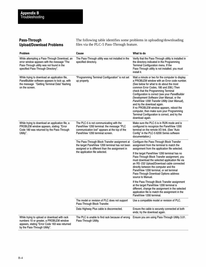
TroubleshootingAppendix B
B-4
The following table identifies some problems in uploading/downloadingfiles via the PLC-5 Pass-Through feature.
Problem Cause What to do
While attempting a Pass�Through Download, anerror window appears with the message �ThePass�Through utility was not found in thespecified Pass�Through Directory".
The Pass�Through utility was not installed in thespecified directory.
Verify that the Pass�Through utility is installed inthe directory indicated in the ProgrammingTerminal Configuration menu. If thePass�Through utility is not installed. you mustinstall it.
ÁÁÁÁÁÁÁÁÁÁÁÁÁÁÁÁÁÁÁÁÁÁÁÁÁÁÁÁÁÁÁÁÁÁÁÁÁÁÁÁÁÁÁÁÁÁÁÁÁÁÁÁÁÁÁÁÁÁÁÁÁÁÁÁÁÁÁÁÁÁÁÁÁÁÁÁÁÁÁÁÁÁÁÁÁÁÁÁÁÁÁÁÁÁÁÁÁÁÁÁÁÁÁÁÁÁÁÁÁÁÁÁÁÁÁÁÁÁÁÁ
While trying to download an application file,PanelBuilder software appears to lock up, withthe message �Getting Terminal Data" flashingon the screen.
ÁÁÁÁÁÁÁÁÁÁÁÁÁÁÁÁÁÁÁÁÁÁÁÁÁÁÁÁÁÁÁÁÁÁÁÁÁÁÁÁÁÁÁÁÁÁÁÁÁÁÁÁÁÁÁÁÁÁÁÁÁÁÁÁÁÁÁÁÁÁÁÁÁÁÁÁÁÁÁÁÁÁÁÁÁÁÁÁÁÁÁÁÁÁÁÁÁÁÁÁÁÁÁÁÁÁÁÁÁÁÁÁÁÁÁÁÁÁÁÁ
�Programming Terminal Configuration" is not setup properly.
ÁÁÁÁÁÁÁÁÁÁÁÁÁÁÁÁÁÁÁÁÁÁÁÁÁÁÁÁÁÁÁÁÁÁÁÁÁÁÁÁÁÁÁÁÁÁÁÁÁÁÁÁÁÁÁÁÁÁÁÁÁÁÁÁÁÁÁÁÁÁÁÁÁÁÁÁÁÁÁÁÁÁÁÁÁÁÁÁÁÁÁÁÁÁÁÁÁÁÁÁÁÁÁÁÁÁÁÁÁÁÁÁÁÁÁÁÁÁÁÁ
Wait a minute or two for the computer to displaya PROBLEM window with an Error code number.(See below for what to do about the mostcommon Error Codes, 180 and 208.) Thencheck that the Programming TerminalConfiguration is correct (see your PanelBuilderDevelopment Software User Manual, or thePanelView 1200 Transfer Utility User Manual),and try the download again.If no PROBLEM window appears, reboot thecomputer, then make sure your ProgrammingTerminal Configuration is correct, and try thedownload again.
ÁÁÁÁÁÁÁÁÁÁÁÁÁÁÁÁÁÁÁÁÁÁÁÁÁÁÁÁÁÁÁÁÁÁÁÁÁÁÁÁÁÁÁÁÁÁÁÁ
While trying to download an application file, aPROBLEM window appears, stating: �ErrorCode 180 was returned by the Pass�ThroughUtility".
ÁÁÁÁÁÁÁÁÁÁÁÁÁÁÁÁÁÁÁÁÁÁÁÁÁÁÁÁÁÁÁÁÁÁÁÁÁÁÁÁÁÁÁÁÁÁÁÁ
The PLC�5 is not communicating with thePanelView 1200 terminal: the message �PLCcommunication lost" appears at the top of thePanelView 1200 terminal screen.
ÁÁÁÁÁÁÁÁÁÁÁÁÁÁÁÁÁÁÁÁÁÁÁÁÁÁÁÁÁÁÁÁÁÁÁÁÁÁÁÁÁÁÁÁÁÁÁÁ
Make sure the PLC�5 is in RUN mode and isconfigured to recognize the PanelView 1200terminal on the remote I/O link. (See �AutoConfig" in the PLC�5 6200 Series softwaredocumentation.)ÁÁÁÁÁÁÁÁÁÁÁÁ
ÁÁÁÁÁÁÁÁÁÁÁÁÁÁÁÁÁÁÁÁÁÁÁÁÁÁÁÁÁÁÁÁÁÁÁÁÁÁÁÁÁÁÁÁÁÁÁÁÁÁÁÁÁÁÁÁÁÁÁÁÁÁÁÁÁÁÁÁÁÁÁÁÁÁÁÁÁÁÁÁÁÁÁÁÁÁÁÁÁÁÁÁÁÁÁÁÁÁÁÁÁÁÁÁÁÁÁÁÁÁÁÁÁÁÁÁÁÁÁÁÁÁÁÁÁÁÁÁÁÁÁÁÁÁÁÁÁÁÁÁÁÁÁÁ
ÁÁÁÁÁÁÁÁÁÁÁÁÁÁÁÁÁÁÁÁÁÁÁÁÁÁÁÁÁÁÁÁÁÁÁÁÁÁÁÁÁÁÁÁÁÁÁÁÁÁÁÁÁÁÁÁÁÁÁÁÁÁÁÁÁÁÁÁÁÁÁÁÁÁÁÁÁÁÁÁÁÁÁÁÁÁÁÁÁÁÁÁÁÁÁÁÁÁÁÁÁÁÁÁÁÁÁÁÁÁÁÁÁÁÁÁÁÁÁÁÁÁÁÁÁÁÁÁÁÁÁÁÁÁÁÁÁÁÁÁÁÁÁÁÁÁÁÁÁÁÁÁÁÁÁÁ
The Pass�Through Block Transfer assignment atthe target PanelView 1200 terminal has not beenassigned or is different than the assignment inthe application file selected.
ÁÁÁÁÁÁÁÁÁÁÁÁÁÁÁÁÁÁÁÁÁÁÁÁÁÁÁÁÁÁÁÁÁÁÁÁÁÁÁÁÁÁÁÁÁÁÁÁÁÁÁÁÁÁÁÁÁÁÁÁÁÁÁÁÁÁÁÁÁÁÁÁÁÁÁÁÁÁÁÁÁÁÁÁÁÁÁÁÁÁÁÁÁÁÁÁÁÁÁÁÁÁÁÁÁÁÁÁÁÁÁÁÁÁÁÁÁÁÁÁÁÁÁÁÁÁÁÁÁÁÁÁÁÁÁÁÁÁÁÁÁÁÁÁÁÁÁÁÁÁÁÁÁÁÁÁ
Configure the Pass�Through Block Transferassignment from the terminal to match theassignment from the application file selected.
If the target PanelView 1200 terminal has noPass�Through Block Transfer assignment, youmust download the selected application file viaan RS-232 Upload/Download cable connecteddirectly between the computer and thePanelView 1200 terminal, or set terminalPass�Through Download Options addresssource to Manual.
If the Pass�Through Block Transfer assignmentat the target PanelView 1200 terminal isdifferent, change the assignment in the selectedapplication file to match the assignment in thePanelView 1200 terminal.
The model or revision of PLC does not supportPass�Through Block Transfer.
Use a compatible model or revision of PLC.
ÁÁÁÁÁÁÁÁÁÁÁÁÁÁÁÁÁÁÁÁÁÁÁÁÁÁÁÁÁÁÁÁÁÁÁÁ
ÁÁÁÁÁÁÁÁÁÁÁÁÁÁÁÁÁÁÁÁÁÁÁÁÁÁÁÁÁÁÁÁÁÁÁÁ
Data Highway Plus cable is disconnected.ÁÁÁÁÁÁÁÁÁÁÁÁÁÁÁÁÁÁÁÁÁÁÁÁÁÁÁÁÁÁÁÁÁÁÁÁ
Ensure the cable is securely connected at bothends; try the download again.
While trying to upload or download with racknumbers 10 or greater, a PROBLEM windowappears, stating �Error Code 163 was returnedby the Pass�Through Utility".
The PLC is unable to find rack because of wrongPass�Through Utility.
Ensure you are using Pass�Through Utility 3.01.
Pass�ThroughUpload/Download Problems

TroubleshootingAppendix B
B-5
Problem What to doCause
ÁÁÁÁÁÁÁÁÁÁÁÁÁÁÁÁÁÁÁÁÁÁÁÁÁÁÁÁÁÁÁÁÁÁÁÁÁÁÁÁÁÁÁÁÁÁÁÁÁÁÁÁÁÁÁÁÁÁÁÁ
While trying to download an application file, aPROBLEM window appears stating: �Error code208 was returned by the Pass�Through Utility".
ÁÁÁÁÁÁÁÁÁÁÁÁÁÁÁÁÁÁÁÁÁÁÁÁÁÁÁÁÁÁÁÁÁÁÁÁÁÁÁÁÁÁÁÁÁÁÁÁÁÁÁÁÁÁÁÁÁÁÁÁ
The Pass�Through Utility has been unable toestablish DH+ communications with the PLC�5.
ÁÁÁÁÁÁÁÁÁÁÁÁÁÁÁÁÁÁÁÁÁÁÁÁÁÁÁÁÁÁÁÁÁÁÁÁÁÁÁÁÁÁÁÁÁÁÁÁÁÁÁÁÁÁÁÁÁÁÁÁ
Make sure the �Programming Terminal DH+Address" and the �PLC DH+ Address" areproperly assigned.
Make sure that you have selected the proper�DH+ Hardware Driver" for your system, and thatthe �DH+ Driver Card Location" code is correct.ÁÁÁÁÁÁÁÁÁÁÁÁ
ÁÁÁÁÁÁÁÁÁÁÁÁÁÁÁÁÁÁÁÁÁÁÁÁÁÁÁÁÁÁÁÁÁÁÁÁ
Immediately after completing a PLC�5Pass�Through Download, a Minor Fault Statusbit is set in the PLC�5.
ÁÁÁÁÁÁÁÁÁÁÁÁÁÁÁÁÁÁÁÁÁÁÁÁÁÁÁÁÁÁÁÁÁÁÁÁÁÁÁÁÁÁÁÁÁÁÁÁ
The rack assignment configuration of theapplication file downloaded to the PanelView1200 terminal did not exactly match theapplication file that was overwritten.
ÁÁÁÁÁÁÁÁÁÁÁÁÁÁÁÁÁÁÁÁÁÁÁÁÁÁÁÁÁÁÁÁÁÁÁÁÁÁÁÁÁÁÁÁÁÁÁÁ
Use the PLC�5 6200 Series software to clear theMinor Fault; then reconfigure the PLC�5 torecognize the new rack assignment.
PLC Controllers Required for Pass�Through
Important Only specific models and revisions of PLC controllers arecapable of the Pass-Through download/upload. Refer to the following tablefor compatible models and revisions.
Processor Series Revision Valid PLC Racks Baud Rates
PLC�5/11 All All 3 octal 57.6 kbps115.2 kbps230.4 kbps
PLC�5/15 B N or later 1-3 octal 57.6 kbps
PLC�5/20 All All 1�3 octal 57.6 kbps115.2 kbps230.4 kbps
PLC�5/25 A J or later 1-7 octal 57.6 kbps
PLC�5/30 A B or later 1-7 octal 57.6 kbps115.2 kbps230.4 kbps
PLC�5/40 AB
E or laterB or later
1-17 octal 57.6 kbps115.2 kbps230.4 kbps
PLC�5/60 AB
E or laterB or later
1-27 octal 57.6 kbps115.2 kbps230.4 kbps
PLC�5/250 All All 1-37 octal 57.6 kbps115.2 kbps230.4 kbps
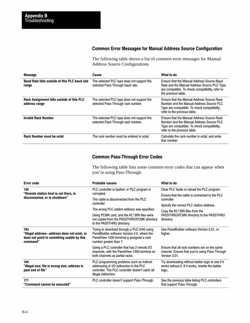
TroubleshootingAppendix B
B-6
Common Error Messages for Manual Address Source Configuration
The following table shows a list of common error messages for ManualAddress Source Configurations
Message Cause What to do
Baud Rate falls outside of this PLC baud raterange
The selected PLC type does not support theselected Pass�Through baud rate.
Ensure that the Manual Address Source BaudRate and the Manual Address Source PLC Typeare compatible. To check compatibility, refer tothe previous table.
Rack Assignment falls outside of this PLCaddress range
The selected PLC type does not support theselected Pass�Through rack number.
Ensure that the Manual Address Source RackNumber and the Manual Address Source PLCType are compatible. To check compatibility,refer to the previous table.
Invalid Rack Number The selected PLC type does not support theselected Pass�Through rack number.
Ensure that the Manual Address Source RackNumber and the Manual Address Source PLCType are compatible. To check compatibility,refer to the previous table.
Rack Number must be octal The rack number must be entered in octal. Calculate the rack number in octal, and enterthat number.
Common Pass�Through Error Codes
The following table lists some common error codes that can appear whenyou’re using Pass-Through.
Error code Probable causes What to do
145�Remote station host is not there, isdisconnected, or is shutdown"
PLC controller is faulted, or PLC program iscorrupted.
The cable is disconnected from the PLCcontroller.
The wrong PLC station address was specified.
Using PCMK card, and the KL*.BIN files werenot copied from the PASSTHRU\PCMK directoryto the PASSTHRU directory.
Clear PLC faults or reload the PLC program.
Ensure that the cable is connected to the PLCcontroller.
Specify the correct PLC station address.
Copy the KL*.BIN files from thePASSTHRU\PCMK directory to the PASSTHRUdirectory
163�Illegal addressaddress does not exist, ordoes not point to something usable by thiscommand"
Trying to download through a PLC�5/40 usingPanelBuilder software Version 4.0, where thePanelView 1200 terminal is assigned a racknumber greater than 7.
Using a PLC controller that has 2 remote I/Ochannels, with the PanelView 1200 terminal onboth channels as partial racks.
Use PanelBuilder software Version 5.01, orhigher.
Ensure that all rack numbers are on the samechannel. Ensure that you're using Pass�ThroughVersion 3.01.
164�Illegal size; file is wrong size; address ispast end of file"
PLC programming problems such as indirectaddressing or I/O indirection in the PLCcontroller. The PLC controller doesn't catch allillegal indirection.
Try downloading without ladder logic to see if itworks without it. If it works, rewrite the ladderlogic.
171�Command cannot be executed"
PLC controller doesn't support Pass�Through. See the previous table listing PLC controllersthat support Pass�Through.

TroubleshootingAppendix B
B-7
Error code What to doProbable causes
180�Timed out, 1771 backplane module notresponding"
PLC controller in program mode, or PanelView1200 terminal in configuration mode.
The Pass�Through block transfer assignment inthe PanelView 1200 terminal doesn't match thePass�Through block transfer assignment in theapplication file being downloaded.
Put the PLC controller and the PanelView 1200terminal in run mode.
Match the address assignments.
186�ACK timeout"
Remote I/O cables are disconnected.
Noisy line.
The computer's address is the same as the PLCstation address, when using a KT or KT2 device.
Ensure that both ends of the Remote I/O cablesare connected and terminated according to thebaud rate used.
Reassign the KT or KT2 address.
190�All others"
Programming terminal is not connected to DataHighway Plus network.
Connect programming terminal to Data HighwayPlus network.
208 �Error Opening Network"
Wrong KT2 driver card location. The switchsettings on the KT2 card don't match thesettings entered in the Pass�Through downloadconfiguration.
Ensure that the settings on the KT2 card matchthose entered in the Pass�Through downloadconfiguration.
211 �Bad configuration file format"
Trying to download through a PLC�5/40 wherethe PanelView 1200 terminal is assigned a racknumber greater than 7.
The switch settings on the KT card don't matchthe settings entered in the Pass�Throughdownload configuration.
Use PanelBuilder software 4.00.02 or higher.
Ensure that the settings on the KT card matchthose entered in the Pass�Through downloadconfiguration. See the following table forinformation on selecting a memory location forthe KT card.
218 �FID mismatch detected"
A rack was configured in the PanelBuilderapplication that is not an actual PanelViewterminal rack.
Reassign the correct terminal rack usingPanelBuilder software.
221 �Unknown external error received from 6200library"
Screen objects have addresses assigned to thePass�Through block transfer file.
The PLC controller or the PanelView 1200terminal don't have an 82�ohm resistor whenrunning at 230K baud on Remote I/O.
The Pass�Through block transfer file in thePanelBuilder application is also being used on aBTR or BTW instruction in the PLC controller.
Assign a different address to the Pass�Throughblock transfer file, or assign different addressesto the screen objects.
Install 82�ohm resistor.
Assign a unique address to the Pass�Throughblock transfer file.
224 �Communications board address incorrect"
PanelView 1200 rack assignment is greater than7.
The KT card bit pattern doesn't match thejumper setting on the KT card.
Use PanelBuilder software 4.00.02 or higher.
Ensure that the settings on the KT card matchthose entered in the Pass�Through downloadconfiguration. See the following table forinformation on selecting a memory location forthe KT card.
For help on solving PanelBuilder software problems, see yourPanelBuilder Development Software User Manual or your PanelBuilder1200 Configuration Software for Windows User Manual.
PanelBuilder Problems

Symbols
**Empty**, 1�1
Numbers
1747-SN I/O Subscanner Module, 1�19
1771-SN I/O Subscanner Modules, 1�19
1772-SD2 Scanner /Distribution panel, 1�18
1775-S4A Remote Scanner /Distributionpanel, 1�18
25 to 9 pin adapter, 3�17
6008-SI IBM PC I/O Scanner, 1�19
6008-SQ DEC Q-BUS I/O Scanner, 1�19
6008-SV VME I/O Scanner, 1�19
A
AC Power Connector, 3�4
AC Power VoltageRange, A�5
Access Code keypad window, 2�9
Access Codes, 2�9
Adapter Cable, 3�18
Alarm Audio, 2�10
Alarm Quantity/Accum Time Reset, PLCControlled, 1�17
Alarm Relay, 1�6, A�6option, 2�10PLC Controlled, 1�17screen, 2�10
Alarm Relay connector, 3�3
Alarm Window, 1�16
Allen-Bradley 6121-CBB Combo Adapter, 3�17
Altitude, A�8
Ambient Operating Temperature limits, A�8
Anti-static precautions, 3�6
Application Data Checksum, 2�24
Application File, P�1
Arcs, 1�15
ASCII Display, 1�15
Audio, PLC Controlled, 1�17
Audio Response Screen, 2�10
Audio Volume, 2�10
Auto Line Feed parameter, 2�8
B
Bar Graphs, 1�14
Battery, 1�4, A�7Failure, 2�24Failure indications, A�7Failure test, 2�4
Battery�backed RAM, P�1, A�6
Block Transfer File, 2�8
Boxes, 1�15
Brightness control (Monochrome terminals), 2�1
ButtonCenter Screen, 2�13Change Access Code, 2�9Change Data, 2�7Choose List, 2�7Clear, 2�3Decrement Value, 1�14Emergency stop, 4�5Go To Screen, 1�13Increment Value, 1�14Interlocked Push, 1�13Latched Input Push, 1�13Load Presets, 2�11Maintained Push, 1�13Momentary Push
(Normally Closed), 1�13(Normally Open), 1�13
Numeric Keypad�Enable, 1�15Return To Previous Screen, 1�13Save & Exit, 2�7Screen Keypad�Enable, 1�15Screen Print, 1�15Set Value, 1�14Test Alignment, 2�13
Button Audio, 2�10
C
Center Screen button, 2�13
Change Access Code button, 2�9
Change Data button, 2�7
Character sets, A�6
Checksum Memory Tests, 2�3
Choose List button, 2�7
Index

IndexI–2
Circles, 1�15
Cleaning, 5�1enclosure, 5�1Keypad, 5�1
Clear button, 2�3
Clear Window, PLC Controlled, 1�17
Clock, 2�12
Color Keypad Terminal Dimensions, 3�10
Color Terminals heat generation, A�8
Color Touch Screen Terminal Dimensions, 3�11
Communication Problems, B�3
Communication Test, 2�5
Configuration mode, 2�1
Configuration Mode Menu , 2�6
ConfigureScreen Saver, 5�2Serial Port, 2�7
Connecting a Remote Alarm to the AlarmRelay, 3�3
Connecting the Programmable Controller, 4�3
Contrast control (Color terminals), 2�1
Control List Selector with Enter, 1�13
Control List Selector without Enter, 1�13
Custom legends, A�2
D
Date Display, 1�14
Decrement Value Button, 1�14
Default settings for Upload/Download, 2�8
Degauss, 2�21
Degauss automatic, 5�2, A�4
Diagnostic Testing, on-line, 2�24
Diagnostics, 1�7
DisplayASCII, 1�15Date, 1�14Local Message, 1�15Numeric Data, 1�14Time, 1�14
Display test, 2�23
Downloading, 1�4, 4�2
Dynamic objects, 1�11
E
EEPROM, P�3
Emergency stop buttons, 4�5
EPROM, P�3
EPROM or EEPROM chip installation, 1�7
EPROM/EEPROM and faults, 2�4
EPROMs or EEPROMs, A�6
F
False Depression Test, 2�14
Fault detection tests, 2�24
Filter, 5�2
Firmware EPROM, P�2
FuseEurope, A�6U.S.A., A�6
G
Go To Screen Button, 1�13
H
Hex Files, P�2
Humidity, A�8
I
Increment Value Button, 1�14
IndicatorList, 1�14Multistate, 1�13
Information Window, 1�16
Install user PROM, 3�5
Installing a User PROM, 3�5
Installing Keypad Terminals, 3�12
Installing PanelView Terminals, 3�11
Installing Touch Screen Terminals, 3�13, 3�14
Interlocked Push Buttons, 1�13
Invalid Screen Request, 2�24
ISA Symbols, 1�14
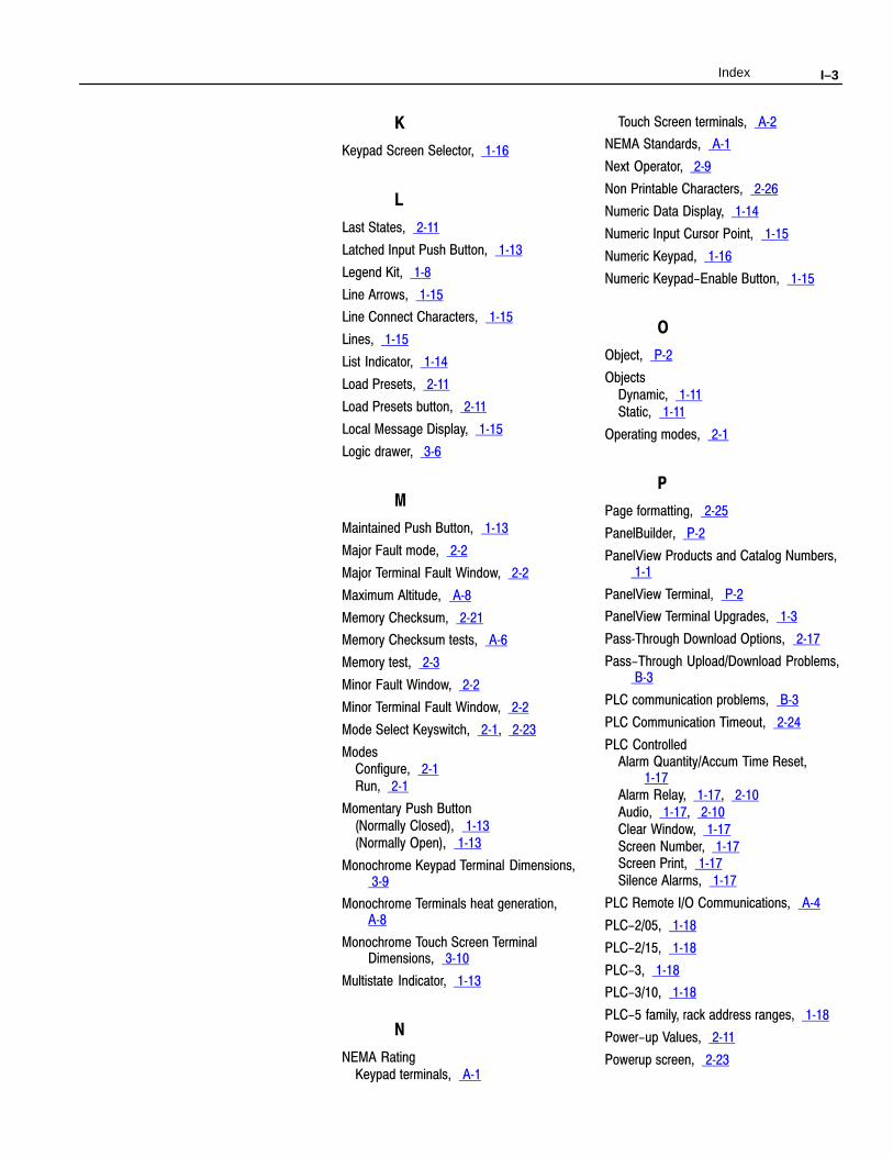
Index I–3
K
Keypad Screen Selector, 1�16
L
Last States, 2�11
Latched Input Push Button, 1�13
Legend Kit, 1�8
Line Arrows, 1�15
Line Connect Characters, 1�15
Lines, 1�15
List Indicator, 1�14
Load Presets, 2�11
Load Presets button, 2�11
Local Message Display, 1�15
Logic drawer, 3�6
M
Maintained Push Button, 1�13
Major Fault mode, 2�2
Major Terminal Fault Window, 2�2
Maximum Altitude, A�8
Memory Checksum, 2�21
Memory Checksum tests, A�6
Memory test, 2�3
Minor Fault Window, 2�2
Minor Terminal Fault Window, 2�2
Mode Select Keyswitch, 2�1, 2�23
ModesConfigure, 2�1Run, 2�1
Momentary Push Button(Normally Closed), 1�13(Normally Open), 1�13
Monochrome Keypad Terminal Dimensions, 3�9
Monochrome Terminals heat generation, A�8
Monochrome Touch Screen TerminalDimensions, 3�10
Multistate Indicator, 1�13
N
NEMA RatingKeypad terminals, A�1
Touch Screen terminals, A�2
NEMA Standards, A�1
Next Operator, 2�9
Non Printable Characters, 2�26
Numeric Data Display, 1�14
Numeric Input Cursor Point, 1�15
Numeric Keypad, 1�16
Numeric Keypad-Enable Button, 1�15
O
Object, P�2
ObjectsDynamic, 1�11Static, 1�11
Operating modes, 2�1
P
Page formatting, 2�25
PanelBuilder, P�2
PanelView Products and Catalog Numbers, 1�1
PanelView Terminal, P�2
PanelView Terminal Upgrades, 1�3
Pass�Through Download Options, 2�17
Pass-Through Upload/Download Problems, B�3
PLC communication problems, B�3
PLC Communication Timeout, 2�24
PLC ControlledAlarm Quantity/Accum Time Reset,
1�17Alarm Relay, 1�17, 2�10Audio, 1�17, 2�10Clear Window, 1�17Screen Number, 1�17Screen Print, 1�17Silence Alarms, 1�17
PLC Remote I/O Communications, A�4
PLC-2/05, 1�18
PLC-2/15, 1�18
PLC-3, 1�18
PLC-3/10, 1�18
PLC-5 family, rack address ranges, 1�18
Power-up Values, 2�11
Powerup screen, 2�23
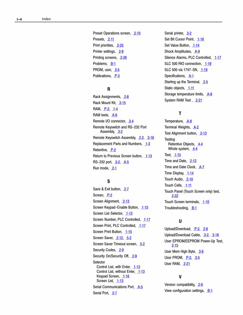
IndexI–4
Preset Operations screen, 2�10
Presets, 2�11
Print priorities, 2�25
Printer settings, 2�8
Printing screens, 2�26
Problems, B�1
PROM, user, 3�5
Publications, P�3
R
Rack Assignments, 2�8
Rack Mount Kit, 3�15
RAM, P�2, 1�4
RAM tests, A�6
Remote I/O connector, 3�4
Remote Keyswitch and RS-232 PortAssembly, 3�2
Remote Keyswitch Assembly, 2�2, 3�16
Replacement Parts and Numbers, 1�3
Retentive, P�2
Return to Previous Screen button, 1�13
RS-232 port, 3�2, A�5
Run mode, 2�1
S
Save & Exit button, 2�7
Screen, P�2
Screen Alignment, 2�13
Screen Keypad-Enable Button, 1�15
Screen List Selector, 1�13
Screen Number, PLC Controlled, 1�17
Screen Print, PLC Controlled, 1�17
Screen Print Button, 1�15
Screen Saver, 2�12, 5�2
Screen Saver Timeout screen, 5�2
Security Codes, 2�9
Security On/Security Off, 2�9
SelectorControl List, with Enter, 1�13Control List, without Enter, 1�13Keypad Screen, 1�16Screen List, 1�13
Serial Communications Port, A�5
Serial Port, 2�7
Serial printer, 3�2
Set Bit Cursor Point, 1�16
Set Value Button, 1�14
Shock Amplitudes, A�9
Silence Alarms, PLC Controlled, 1�17
SLC 500 RIO connection, 1�19
SLC 500 via 1747-SN, 1�19
Specifications, A�1
Starting up the Terminal, 2�5
Static objects, 1�11
Storage temperature limits, A�8
System RAM Test , 2�21
T
Temperature, A�8
Terminal Weights, A�2
Test Alignment button, 2�13
TestingRetentive Objects, 4�4Whole system, 4�4
Text, 1�15
Time and Date, 2�12
Time and Date Clock, A�7
Time Display, 1�14
Touch Audio, 2�10
Touch Cells, 1�11
Touch Panel (Touch Screen only) test, 2�22
Touch Screen terminals, 1�10
Troubleshooting, B�1
U
Upload/Download, P�2, 2�6
Upload/Download Cable, 3�2, 3�16
User EPROM/EEPROM Power�Up Test, 2�15
User Mem High Byte, 3�6
User PROM, P�2, 3�5
User RAM, 2�21
V
Version compatibility, 2�6
View configuration settings, B�1

Index I–5
W
WatchdogCircuit, 2�5Test, 2�5
Window, P�3Alarm, 1�16Information, 1�16

With major offices worldwide.
Algeria • Argentina • Australia • Austria • Bahrain • Belgium • Brazil • Bulgaria • Canada • Chile • China, PRC • Colombia • Costa Rica • Croatia • Cyprus • Czech
Republic • Denmark • Ecuador • Egypt • El Salvador • Finland • France • Germany • Greece • Guatemala • Honduras • Hong Kong • Hungary • Iceland • India •Indonesia • Israel • Italy • Jamaica • Japan • Jordan • Korea • Kuwait • Lebanon • Malaysia • Mexico • New Zealand • Norway • Oman • Pakistan • Peru • Philippines
• Poland • Portugal • Puerto Rico • Qatar • Romania • Russia-CIS • Saudi Arabia • Singapore • Slovakia • Slovenia • South Africa, Republic • Spain • Switzerland •Taiwan • Thailand • The Netherlands • Turkey • United Arab Emirates • United Kingdom • United States • Uruguay • Venezuela • Yugoslavia
World Headquarters, Allen�Bradley, 1201 South Second Street, Milwaukee, WI 53204 USA, Tel: (1) 414 382�2000 Fax: (1) 414 382�4444
Allen�Bradley has been helping its customers improve productivity and quality for 90 years.
A�B designs, manufactures and supports a broad range of control and automation products
worldwide. They include logic processors, power and motion control devices, man�machine
interfaces and sensors. Allen�Bradley is a subsidiary of Rockwell International, one of the
world's leading technology companies.
Publication 2711-812—June 1994 40061-249-01 (A)� 1994 Allen-Bradley Company, Printed in USA