Panasonic JU455-5 Service Manual r PART. I 1. INTRODUCTION This service manual consists of two...
27
Panasonic ORDER NO. M SD850902 900 Flexible Disk Storage Drive ,,",U-455-5 Matsushita Communication Industrial Co., Ltd. Memory Systems Division 3-1, 4-c home, Tsunashima- Higashi Koh oku -k u, Yokohama 223 JAPAN
Transcript of Panasonic JU455-5 Service Manual r PART. I 1. INTRODUCTION This service manual consists of two...

Panasonic
ORDER NO. M SD850902900
Flexible Disk Storage Drive
,,",U-455-5
Matsushita Communication Industrial Co., Ltd. Memory Systems Division 3-1, 4-chome, Tsunashima-Higashi Kohoku-ku, Yokohama 223 JAPAN

CONTENTS
PART I
1. INTRODUCTION "- ..•.••.••...••..•••.••.....••.•..•.. .. ... .. . •... .••• ••...••..•....•... .... .. .. .•. . ...• .. •••.. ••....•.••. •. ••.•. 2 . MODELS AND MDOOEL NUMBERS ..................................................... ... ............. .... ................... . 3. SPECIAL TOOlS ·············· · ········ ····· ····· ················ ......... ..... .......................................... ... ... .... .. .
4. 5.
••
7.
•• g.
10 .
11 .
OUTLIN E OF MAINTENANCE .• .••. •.•..•• .•••....•...••...•. . .••..•.. •••...•....• .•. DIAGNOSTIC PROCE DURES . .................. . ..... . ......... . .• . . ... ..... . ..... . . .. ..... . . .. ........... . .. .. ....... ........... .. 5.1 Error Symptom Recognit ion ...... .. .. .. ............ .. ................ .. ...... . .. . . .. ........... ...... ...... ....... .... .
5.2 50ft Error Detection and Correction ....... .... ....... ........ .. ...... ........ .......... ......... .. ................... .
5.3 5.4
Write Effor . ............. .. ......... ....................................................................................... ..
Read Error ... .... .. . ... ........................ .. ... ....... .. ..... .................. .. .... .. ..... ........ ......... . 5.5 Seek. Effor .... . .. ... .... . ....................... .... . .. ..... .......... . .. ............. .. ... . . . .... . . 5.6 Compatibil ity Error .. ... .......... ... ............ .. .... ........... ....... ....... ................. .............. . TROU8LE ANALYSIS ........................ .. ............. .. ..................................................................... . .
6.1 Trouble AnalysIs Procedure .. .................... -.. ......... ............... . ........ ...... ... ..... ... .. . ... .. 6.2 Trouble Shooting .. . ... .... ........ ..... ........ .... ...... ........ .. . . . . .. . . ... ............ .... .... .......... ..... . 6.3 Trouble Analy~is Table' . . .......... .. . ......... ... .. . .... ... ............ .. ... ...... . . .. ........... . .... .. . ...... .. . PREVENTIVE M AINTENANCE .. ....... ...... . ............................... ... ....... .. ... ...... ........ .. .. ...... ..... .......... . M EASUREMENT ITEMS FOR EACH MODEL ... ................................. .. ........ ........................................ .
ADJUSTM ENTS AN D VERIFICATIONS .. .... .............. ... ........... ...... .. .. ... .. ........ ..... ......... . . . ... .... . .. 9 .1 Motor Speed Adjustment and Verif ication (Inde~ Period) . ........ ... .. . ..... .. . ... . ... .. . . . ..... . . . ..... .. 9.2 Write Protect Verif ication ...... .. .............. . . .. ............ ... ............... . .... ........ . .. ........... .. 9 .3 Head Output Veri f icat ion ....... ... .. ............ ................ .... ...................................... . 9 .4 Output Modulation Verif ication ........................................................................ ... ......... . 9.5 Radial Al ignment Adjustment . ... ......... ... .. ...... ..... . .. ............ . ... ........ .. ... ..... . .. ................ .. . .. . 9.6 Azimuth Verification ...... . .. ... .. ...... .... . .. ... ... . .. . .. ...... . ................ ............. ... .................... . 9.7 Inde~ Burst Ver ifications ...... . ..... . . . ....... . . . .. . . .... ....... .. ........... ........... .. ..... ...... ............. ... . 9 .S Tr"c~ 00 Sensor Adjustment .... · .. ·· ...... ··· .. ···· · · ............ .. .... ............. ................................ . .. . 9.9 Limiter Verifications (5.25·inch) .... ·................... ......... .. ........ ..... ............ ......... .... ........ . 9.10 limiter Adjustment (3 .S·inch) ..................... .... ........... ................................ .......... . ... .. 9.11 Asymmetry Verifications ..... .... . .. .. .......... ... ......... ...... .. . . . .. . . ........ .... .. ... . ..... . ... .. ..... . PANASONIC ALIGNME NT DISKETTE ............. ...................... ... .. ........... . . . . . . . .. ............ ..... .
PART!!
REMOVALS AND IN STALLATIONS .. · .... · · · .... · .. · ............ · ........ . . ...... ... ... ..... .. ............................ . .. .... . 11.1 PCB Removal and In5tallatlo(\. .... .. . .. .......... ... ............... ... .......... ... . .. . .. ..................... .. . ... .... . . 11.2 Front plate Removal and Installation .............. ......... .... ... ............................. ..... ... .. ............. . 11.3 Track. 00 Assembly Removal and Installat;on· .. · .... .. · .. · ..... .. · .. · ......................... .... .................... . 11.4 Collect Assembly Removal, Installation and Adjustment ... . .. ...... ......... ... .. ...... .. ... ..... ................. .. 11 .5 Clamp Assembly Removal and Installation ......... .......... ............ ......... ........... ... ........... .. 11 .6 Write Protect Sensorllnde~ Detector Assembly Removal and Installation . ... ..... ........ .... .•...... . .. . . . . .. .. . 11.7 Cartridge Guide Assembly Remova l and Installation ......... ..... .......................... . .. .................. .... . I I .S Stepper Motor Assembly RemOval and Installation ........... ..... ............ ....... ............................... . 11.9 COlIrriage Arm Assembly Removal and Installation. .......... .. . ....... .. ... .... . .. ......... ...... ....... ..... ... ..... . 11.10 Drive Motor Removal and Installat ion .... .. ... . ... .......... .. . . ....... .. ... .. .. . .. .......... .. ............... ....... .
, 1.11 LED Assembly Removal and Installat ion ......... ... ...................................... ...... . .......... ..... ... . ..
12. TEST POINTS .... ............................ ...................................................... .................................. . 13. EXPLODED ViEW· .. ··· .. · .... ·· · ...... · · · . .. · .. .. ............................................................. ........ .. ........ .. . .. 14. REPlACEMENT PARTS LIST ........... . ...... ........ ..... ... . . ... ... . .. .... ..... .......... ..... . .... .. ...... .. ...... ..... ..... . .. .. 15. REPLACEM ENT PARTS LIST OF PCS ...... . . .... .............. .............. ..... .......... ..... ............ ..... ........... ...... .. 16. SCHEMATIC DIAGRAM ... . . ... ............. ............. .... .... .......... ............ ...... ....... .... ....... ............. ...... .. 17. CIRCUIT BOARD ................................ ............................... .... .............. .... ......................... ..... .. lB . BLOCK DIAGRAM ... .......... .................... ........... ......... ...... ....... ............. ..... ........ ........ ........ ..... .. .
Page
2 2 2 2 3 3 3 3 3 3 4 5 5
• 7 7 7 7
• • 10 ID 11 11 11 11 12
13 13 13 13 14 14 15 15 16
16
17
17
18
" 20 21 22 23 24
•
•
•
• t
•

r
r
PART. I 1. INTRODUCTION
This service manual consists o f two parts, Part I covering mainten<lnce description, adjustment procedures, and trouble analysis lmd Part II disassembly and reassembly procedures parts list, and PCB circui ts. Part I encompasses maintenance innructions for all FDD models. Refer to the applicilble items, lind perform maintenance
work on the FOD.
2. MODELS AND MODEL NUMBERS
2.1 5.25·inch FDD
2.2 3.S-inch FOD
~'2'I .. ~~~'~'~'~'J--,-- 48TPI --'L-- JA·SSX
JU.455
JA·550
LJA.551
l .5-inch FOO
96TPI --,... __ JA.56X ---,-- JA·560
L- JA •561
JU·ssx - - CL- -JU.581
JU·S85
JU·59)( - --,-- JU·591
L-JU.595
61.STPI - --- - JU·31)( -r= JU·312
JU-313
J U·] 14
135TPI I JU':,2X
L Ju .J6x
-r= JU.322
JU·323
JU-J24
-r= NJ6'
JU-363
JU-364
3. SPECIAL TOOLS The fol low ing special tools are used for FDO maintenance .
TABLE 3.1
Part No. Tool S .25ti n~ht~TP~ 5.2S.,nch(95TPI)
'.·'6.'IU"U , .. ·sa",.<1, .... " Exerciser FDD·Ex:r~·S .. ~ ,. ~
Alignment diskette I 817-128 817-560 I 817·581 ., Work d iskette , 2D, ~'.~, 2DD 2HD . ---- ----CMOSmL adaptor AI'" Limmiter Adfust Tool (S.25-incl-l)
;;. ,
Oscil loscope (SO MHz) .,' Probe (10: 1) " . ,;;$l Frequency cou nter
. - "f'" Note: *" _: Stand for the same as lett.
: DAD (Dynamic Alignment Diskette) - 1 -
3.S-inch Qua nti ty
"'~ 1
JU.(I1AA 1-2
(DAD only)
2DD 1-2
YTFDD-CN35 1
1
1
3
1

4. OUTLINE OF MAINTENANCE
• The following tools ate required for maintenance of a Floppy Disk Dri ve. (FOO)
4.1 Alignment Diskette
Alignment diskette is used for nead actuator al ignment and index sensor adjustment .
• Ad;tiuments (Refer to table 8.1)
(1) Specify an appIJcable model from label 8.1. CInd make a readlwrite head radial adjustment at a specified tracle . (SidesQ,l)
(2) Make an iodell timing adjustment at a specified Irack . (Sides O. 1)
(3) Make iHI azimuth measurement at a specified tracle (Sides 0, 1) CAUTION
Do not write when using alignment diskette.. Check that write protect sensor is properly operating.
4.2 Exerciser
The exerciser enables you to make all ad justments and inspections necessary for an FDD. Its functions include the following:
(1) Seek increment or alternate tracks (2) Read (but no data compare) (3) Write 1 F or 2F (AIIO'sor " s)
(4) Head load (S.2S-inch FDD with optional head loader) (5) Recalibrat ion to track 00
The exerciser has switches and indicators to execute a specified function .
5. DIAGNOSTIC PROCEDURES
5.1 Error Symptom Re<ognition
Errors that occur because of the wrong operating procedure, wrong programming, or use of a defective diskette, or soft errors due to external causes, such as contaminated air and random electrical noise, are often attributed to a drive failure or maladjustment. Unless a visual inspection of the dri ... e reveals an evident auembly fault or II defect, always confirm errors with another good
diskette, and another known good dri ... e.
5.2 Soft Error Detection and Correction
Soft errors are normally caused by the following: (1) Contamination between read I write heads and diskette. This kind of cont.}:,lination can be easily ehminated by the liner in
the diskette. (2) Random electrical noise, normally a few microseconds or less . (3) Small defects in written data and l o r tfaclr. not detected during write operat ion may cause roft errors dur ing read .
(4) Faulty grounding of the dr .... e or host system can also cause a soft error. (5) Wrong motor speed is another cause of soft errors.
Take the following steps on the controller side to recover from the soft errors mentioned above. (1) Read the track again ten times or until the data is recovered. (2) If Step (1) above fail s to recover the data , access the adjacent. Then return the head to the original track.
(3) Repeat Step (11 . (4) Any error that cannot be corrected by the above procedure is irrecoverable .
- 2 -

5.3 Write Error If an error occurs during write operation, it is usually detected during the next revolution by performing a read opera· tion called write check. To correct an error, write again and repeat a write check operation. If the result is unsatisfactory after ten or more write operations, perform a read operation on another track to determine whether it is the diskette o r the drive that is wrong . If an error persists , replace the diskette and repeat the above procedure.
If the error still persists, consider the drive defective. If the error is corrected, dispose of the diskette as defective.
5.4 Read Error Most read errors are soft errors. Da ta can be recovered by foll owing the recovery procedure mentioned in 5.2.
5.5 Seek Error (1) Stepper motor or stepper motor drive circuit is faulty . (2) Faulty ca rriage
There are two ways of seek error recovery. One is to recalibrate to track 00, and seek back to the original track. The other is t o read the 10 field, check the track number on which the head is located, and move the head away
from it. And read it again.
5.6 Compatibility Error
The data which is written by one drive may not be read by another. Th is error is called a compatibility error, which
can be c.,used mOitly by the fonowing . The check points are ., Iso mentioned below: (1) Head misalignment: Refer to (Adjustments a nd Confirmation Item 9.5)
(2) Head output too low: Refer to (Adjustments and COnfirmation Item 9.3)
(3) Motor speed difference: Refer to (Adjustments and Confirmation Item 9.1)
6. TROUBLE ANALYSIS
To determ ine the cause of trouble whether it lies in the FDD, diskette, or controller, replace the d isk and FDD with good ones. If the FDD is assumed faulty as a resu lt, follow the procedure below.
6.1 Trouble Analysis Procedure
FDD trouble may occur in any of the following ten forms. (1 ) Index detection failure (2) Not ready (3 ) Track 0 undetectable (4) No seek (5) No write (6 ) No read (7) Read error (8) IN USE LED won' t light. (9) Write protect undetectable
(10) No head load 15.25 ·inch FDD with optional head loader)
Check with the troubleshooting flowchart in 6.2.
CAUTION :
Be sure to switch power off before removing an FOO or PCB from the operating svnem.
- 3 -
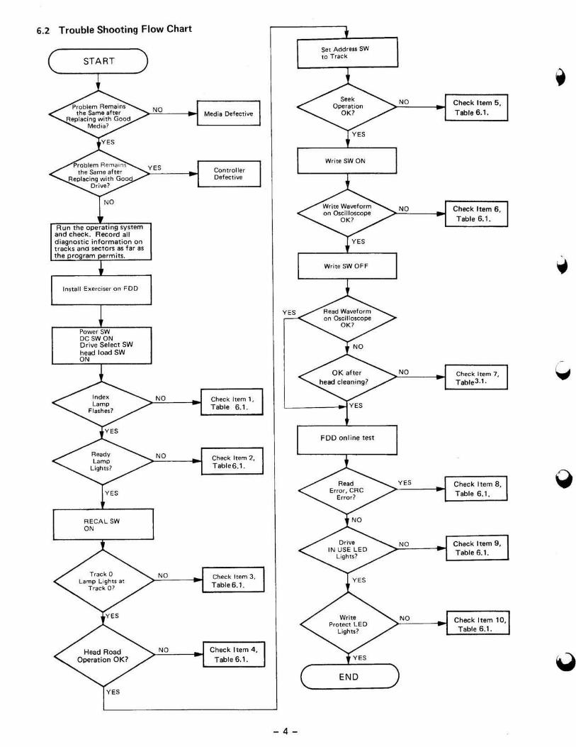
6.2 Trouble Shooting Flow Chart
START
- 4 -
Set Addru. SW 10 Track

6.3 Trouble Analysis Table Table 6.1
Item Trouble No. Cause S.2S·j'ndi JU-3x3 ,.. JU-3x2
1 Index detection 1 Collet art fault R. lace, ,
fai lure 2 DO motor (Ontlol PCB ~~eploce Replace DO motor. Replace 00 motor
~liIpllM':e : : :~: : Base assembly assemblV
3 DO motor faulty
4 Index LEO faultv f':Il!'pl<IC!, : :\: Replace DO motor.
5 Index detector faulty RePlaCe ::,:,:, ::: Base assembly Replace
6 Index LEDlindex det!!Ctor ins tallation faultv Adj , ,
7 PCB motor ON circuit R'epalr *, - *: -• PCB index detection circuit Repair , , ;i, - >;, -2 Not ready 1 See Item 1. ' ? ... . 2 PCB ready circuit Rep~ir '.' *, - ,;,' -3 Track 0 detection 1 Track 00 a~5embly :',.AeplltC!I !!i - if. -failure 2 PCB Irack 0 detection failure Rapai, * < :!, -4 Na head loading 1 See Item 1, N, .'CA? ) . 2 See Hem 2,
3 HOL solenoid :::RePt~e :( 4 PCB HDL tircuit Repair >;( - , .. <
5 Na seek , Stepper motor Rephke ""''-::~ )" - ;;; -2 Guide shaft (Ontamination or damaged Repix.e:: :) ii~ < )" -3 PCB stepper dr iver circuit 'Repai'r rh<W ;-" - ::'. < 6 NoWR ITE , See Item 1. i·' ••••
2 See Item 4. \iF' '" .,., 3 Head disconnected R.epface , ::; - 3;: <-4 Hlilad shorted Replace ' ::': ,:: - :!' -5 HDL bail height wrong Adj:=:'
6 PCB write circuit Aepai~ , :,s: < ;,~ -7 No READ , See Item 1. ..... .
2 See Item 4 . .,. ,.,,'.
3 See Item 6. ..' 4 PCB read circuit Rep'air , ,&
1' \ - '" -• READ ERROR , See Item 1. .....
2 See Item 4 . 'I' \ .•.• , 3 See ItemO".
, ' . ..
4 Alignment Adj. ...... ;:; - ;;, -5 Azimuth ,Uiladjuuable ,i; - ;:: < 6 Burst Ad(,' ? Unadjustable UnlKljUSlable
7 Asymmetry AOj. Adj .
• Limiter UQadjuSfable :; Adj. Adj. , FlagO 'Adj, >;: - '" < 10 HOl t ime p,dj , '" " Index period ~dj,; , •... ".:',. Replace DO motor, Replace
Base ;5Ssembly 12 PCB read circuit Repair' :;: < ;-So -, IN USE lEO , LEO part fI"plece ':"" .-.~ m - ~ -won't light. 2 PCB IN USE circuit Repair .i ,,: -'0 Write p rotect , Write protect part fI~l8(;e
R.plKODD_. ... Replace .... '" failure 2 Write protect circuit .'~ . , :I: - ,,~ -
Note: ii, (-: Sta nd for the same as lett.
7. PREVENTIVE MAINTENANCE No preventive mainte na nce is necessary far any type of FODs under normal conditions of use.
- 5 -

8. MEASUREMENT ITEMS FOR EACH MODEL
Table 8.1
•• m Parameter JU-312, 313,314 JU·32X,36X JU-581,S85
TRK Value TRK Value TR K Value
1 Index period 20 200t3ms 40 200 ± 3ms 32 166.7 ;!; 0.2 m5
2 Output level 39 16OmVor 7' 180mVor 76 120mVor more more more , Radial Alignment 20 75" 40 50% 32 70%
4 AZIMUTH 20 ± 18' 40 ± 18' 68 ± 18'
5 Index burst 20 3±1.5ms 40 3±1.5ms 68 200 t 200 III
6 FLAG 0 From track 1 ' ;1 From track 1 1: 1 From track 2 1: 1 totTack 2 totra,k 2 totTack 3 and back and back. and back
7 limiter -1 Recalibrate -1 Recalibrate - 1 Recalibrate and return to and return to and return to
0 0 0
• Asym metry ,. <6oons 7. <600ns 76 <3 50 ns
• Head load t ime <50m5
JU-591, 595, 475 JU-45S/465 JU-455·5 • • m Para mete r
TRK VALUE TRK Value TRK Value
1 IndelC period 32 166.7;!; 16132 200± O.2 ms 16 200±0.1 ms 0.2 ms
200t (High)
0 .2 ms c) • (Low) .... ,
2 Output level 76 120 mllo( 39n9 1401120mV ,. 140/mllor more or more more , Radial Alignment 32 70% 16132 70% " 70%
4 AZIMUTH 6. ± 18' 311/68 t 18' 34 ± 18'
5 Index burn 6. 200t 311/68 200t 34 200 t 200p.s 200 }ls 200jU
6 FLAG 0 From track 2 1: 1 From track 1 1: 1 From track 2 ,; 1 to track 3 to track totrack 3 and back 2ltrack 2 to and back
track 3 and back 'C<.
7 Limiter -1 Recalibrate -1 Recalibrate -1 Recalibrate and return to and return to arid return to
0 0 0
• Asymmetry 76 <350 ns 39n9 <600 n$ 3. <600",
• Head load t ime <50 m$ <50ms i" ....
- 6-

9. ADJUSTMENTS AND VERIFICATIONS
9.1 Motor Speed Adjustment and Confirmation !Index Period)
(1 } Insert a diskette, run the motor, and damp, Refer to the index period column of Table 8 .1 for the applicabl e
model . (2 ) Step to the specified track. (3) Connect a frequency counter to the INDE X signal.
. 5.25 ,-inch : TP7 3.5·inch: IX
(4 ) Check that the frequency counter read ings meet the specifications in the table.
(5) Adjuument 5.25 -inch: Turn the speed control potentiometer on the motor control circuit board unt il the spedfic:atisons are sat isfied .
3 .5-inch: No ad justment
9.2 Write Protect Verification
(1) Check that the exerciser's write protect lamp goes on and oft as a media is inserted and removed as speci fi ed in the table below.
Media with write protect Media with write protect hole open hole closed
S.2.S-inch OFF- ON
3.5·inch ON OFF
9.3 Head Output Verification
Use a new diskette i1 possible to identity head fa ilure fo r thi~ check.
(1) Insert a good diskette. (2) Run the motor. (3) Step to the track specified in the outpu t leve l column of Table 8.1 . (4) · Connect the oscilloscope probe as specified below.
CH1 CH2 EXT
S.2S ·inch l Pl TP2 TP7
3.5·"lCh T1 T2 " UN DE X}
Invert channel 2 and select the Add mode. Set vertical deflection to 10 mV/ div ision and horizontal deflection to 20 ms/d ivision .
(5) Write 2F (all o nes) on the entire circumference. (In caseot a double·sided FDD, repeat it on sides 0 and 1 using SIDE SE LECT.)
(6) Check that the avtrage output level meets the specificati ons of Table 8.1. If it does not meet the specifications, refer to Item 7 of the Trouble Analysis Table.
- 7 -

9.4 Output Modulat ion Verification
Modulation: M is calculated by the following formula . Vmax-Vmin
M(%) .. )(100 using the value obtained in 9 .3 , and check that the Vma)(+Vmin
calculated value is 20% or less.
_____ _ _____ ~~;:::~:.::i2====Mal(imum Voltage Valve: Vma)( -------~----~- ----""" 7% Average Voltage
Minimum Voltage Valve: Vmax
Fig. 9.1 Modulation
9.5 Radial Alignment Adjustment
Introduction This adjustment Is normally not necessary. rf the mounting screws for the stepper motor loosen, Of if parts become defective, or it a wmpatibility error occurs, check and readjust according to the following procedure. Ste~ (4) to (9) should be performed regardless of the type, CE or DAD alignment diskette used. Use an alignment ' diskette suitable to the type of FDD to be adjusted according to table 3.1.
( 1) Insert an alignmen t diskette. CAUTION: Be sure to 1"lIe th, , Ullnm..,t disk.n, under room conditions tor 20 minutes b,tor' , dju,'m,nt.
(2 ) Step to the track specified in the Radial alignment column of Table 8.1.
(3) Leave the oscilloscope in the same condition as mentioned in section 9.3 .
• Cats Eye System S.lS-inch (4) Check the output waveforms for sides 0 and 1. They should appear as in Fig. 9.2. (5) The two waveforms shou ld appear in the ampli tude ra tio in the R/A column of Table 8.1 or better. (6) If the specified ratio is not satisfied, loosen the two mounting screws for the stepper motor. (n Move the stepper motor along the base by hand until the two waveforms assume approximately the same ampl i·
tude, and retighten the mounting screws. (See Fig. 9.2.) (8) Step the head outward (track 0 ) and inward (track 40 or 79), and confirm that the adjustment has been completed. (9) After the rad ial adjustment, be su re to confirm track 00 senso r ad justment 9,8 and carriage limiter 9.9 .
- 8 -
•

r /
r / 1/ 1\ r \
'\,
Fig. 9.2
-
1'-. / I'
1\ / -
A \ B \
/ i\ J V \ -
V '\ L-V -
Radial Alignment Waveforms (CATS EYE)
A > B
B>A
_l -A _ A -S
)( 100
II lOa
Nota: Sides 0 and 1 a,.. adjusted to agree at the 'actofY . If they disagree, adju" them to meet the specifintions of Table 8.1
• DAD (Dynamic Alignment Diskette) 3.5-inch (4) Watch the output waveforms for sides 0 and 1. They should appear as shown in Fig. 9.3. (S) Measure the timing levels Al to A4 and 81 to 84 in Fig. 9.3, and calculate the lobe ratio from the following
formulas. EB }:A x100%
EA ~ A < EB: EB x 100%
(6) The lobe ratio ulwlated by the above formulas should meet the specifications on item 3 of Table 8.1. (7) If the above requ irement is not met, loosen the two mounting screws for the stepper motor, adjust. (8) Seek from track 0 to track 40 and f rom track 79 to track 40, and confirm that the adjustment has been completed.
(9) After the rad ial adjustment, be sure to confirm track 00 sensor adjustment 9.8 and head (arriage li~iter 9.9. Note: An alignment instrument for 3.5-inch FOOl permits accurate and easy adjustment because the lobe ratio is displayed on
the instrument.
[J,-------------------------u--
Fig. 9.3 Alignment Waveform (DAD)
- 9 -

9.6 Azimuth Verification
(1) Insert an alignment d iskette. Seek to the track specified in the azimuth column of Table B.l . (2) Set the oscilloscope in the same conditions as in B.3, and set ho rizontal deflection to 0 ,5 ms/division. (3) Measure as shown below. (4) Confirm that the measured value meets the specifications in the azimuth column of Table B.l ,
B c
B C c o A
B
A 0 A
:!
A )!,m u(h 0 wave form$
CaseofB > C C_ofB < C
o
B- C Azimuth · B _ D >( (AI
C - B Azimurh ,. --- x (AI
C - A
9.7 Index Burst Verification
3 .5·inch IAI : CE - 30' DAD - 15'
Fig. 9.4 Azimuth Waveform,
S.2S·inch 1M : 12'
(1) Insert an alignment d iskette. Seek to the track spec ified in the li B column of Table B.l . (2) Set the oscilloscope time base as follows:
S.2S ·i nch: 50 ps/division 3.5-inch : 1 ms/d ivision
(3) Check that the time from oscilloscope start to the first data pul se meets the 1/8 specifications of Table 8.1 . (DAD system)
(4) It the specificat ions are not met, adjust as follows. (No adjustment necessary for 3.5·inch models) • Loosen the index detector mounti ng screws enough to free the assembly. • Adjust the timing to 200 ± 200 p sec. • Retighten the screw. • Check the timing again .
I" Indell. Burst .. /
v
Fig. 9.5 Index Timing
- 10 -
•
•
•
•
•
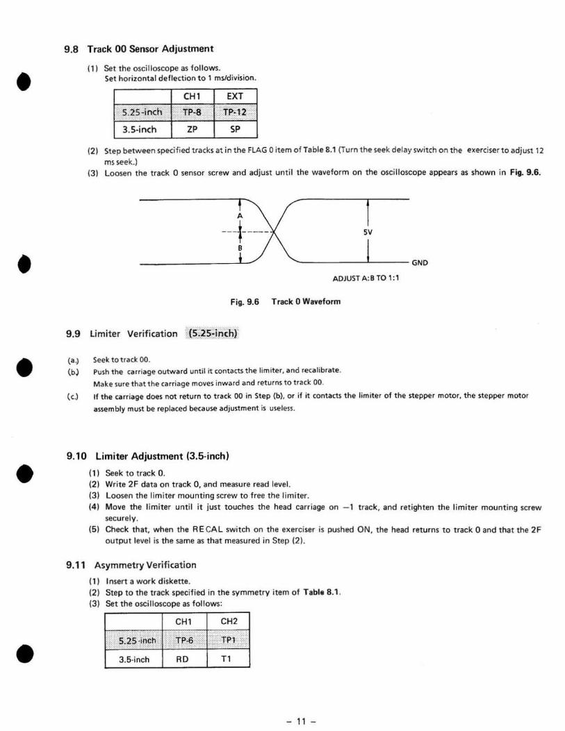
9 .8 Track 00 Sensor Adjustment
(1) Set the oscilloscope as follows. Set horizontal deflection t o 1 mYdivision.
CH1 EXT
S.2S-inch TP-8 Tp·12
3. 5·inch zp SP
(21 Step between specified tracks at in the FLAG 0 item ofTable 8.1 (Turn the seek delay switch on the exerciser to adjust 12
ms seek.) (3) loosen the track 0 sensor screw and adjust until the waveform on the oscilloscope appears as shown in Fig. 9.6.
A
--+---- sv
'---------~------GND
ADJUST A:B TO 1: 1
Fig. 9.6 Track 0 Waveform
g,g limiter Verification (S;)S:inchr
(a.)
(b)
Seek to track 00. Push the carr iage outwllrd until it contacts the lim iter, and recOlIlibrate.
Make sure that the carriage moves inward and returns to track 00.
{el If the carriage does not return to track 00 in Step (b), or i f it contacts the limiter of the stepper motor. the stepper motor
assembly must be replated because adjustment is u§eless.
9 .10 limiter Adjustment (3.5-inchl
(11 Seek to track O. (21 Write 2 F data on track 0, and measure read level. (31 Loosen the limi ter mounting screw to free the limiter. 141 Move the limi ter until it just touches the head carriage on - 1 track. and retighten the limiter mounting screw
securely. (5) Check that, when the A E CA L switch on the exerciser is pushed ON, the head returns to t rack 0 and that the 2F
output level is the same as that measured in Step (21.
9.11 Asymmetry Verification
(1) I nsert a work d iskette. (2) Step to the track specified in the symmetry item of Table 8 .1. (3) Set the oscilloscope as follows:
CH 1 CH2
S.2S -inch TP-6 .. II TP' /
3.5·inch RD T1
- 11 -

(4) Write If.
(5) A read walle form is displayed on the oscilloscope as shown in Fig. 9.7. (6) Confirm if it 1atisfies the villue as shown in Fig. 8.1.
- <: .--_ .. .. .. . - - -- _ .
f--T
Fig. 9.7 Asymmetry Waveform
10. PANASONIC ALIGNMENT DISKETTE
Table 10.1.
TPI PIN Index Azimuth Burst -:,:
:" 8 t 7· t 28 :::. 10 " '" 34TRK 34TRK
48 .. , -
',' '"
68TRK 68TRK 96 817-560
68TRK 68RTRK 96 817·581
61TRK 61TRK 100 817-570
Table 102 . . 3.5 inch Alignment Diskette
TPI PIN Index Azimuth Burst
20 20 67.5 JU-0 1AA
40 40 135 JU-01AA
- 12 -
• . ..
•
• Radial MODEL
/' 16TRK JA-55X .. JU·45S
32TRK JA-56X JU-465
32TRK JU-475 • JU-58X JU-59X
36TRK JU-570
Radial MODEl
20 JU-3 1X
40 JU-32X JU-36X •
•
•
•
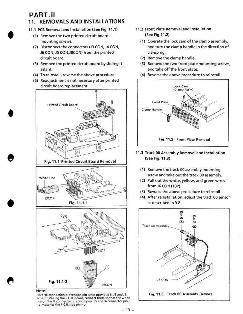
PART . 11 11. REMOVALS AND INSTALLATIONS 11 .1 PCB Removal and Installation (See Fig. 11 .1)
(1) Remove the two printed circuit board mounting screws.
(2) Disconnect the connectors (J3 CON, J4 CON,
J6 CON,)5 CON,J8CON) from the printed
circuit board. (3) Remove the printed circuit board by sliding it
aslant. (4) To reinstall , reverse the above procedure. (5) Readjustment is not necessary after printed
circuit board replacement.
Printed Circuit Board
8
Fig_ 11 .1 Pri nted Circuit Board Removal
11.1-'
J6CON
Note: :::el'ese connect ion prevention pin is not provided in 13 and J6. ,', '-e:': install ing the P .e.e . board, connect them so that the white ·c or. ! ne B (onnector is fa ci ng upwards and J6 connector pin
' ,: . - .a:t.,es the p.e.B. side pin No.
- 13 -
11 .2 Front plate Removal and Installation (See Fig.11.2)
( 1) Operate t he lock cam of the clamp assembly, and turn the damp handle in the di rection of clamping.
(2) Remove the clamp handle. (3) Remove the two front plate mounting screws,
and take off the front plate. (4) Reverse the above procedure to reinstall.
Clamp
Lock Cam (Clamp Ass'vl
Fig. 11 .2 Front Plate Removal
11.3 Track 00 Assembly Removal and Installation (See Fig. 11.3)
(1) Remove the track 00 assembly mounting screw and t ake out the track 00 assembly.
(2) Pull out t he white, yellOW, and green wires from J6CON (lOP) .
(3) Reverse the above procedure to reinstall. (4) After reinstal lation, adjust the track 00 sensor
as described in 9 .B.
Trac:: k ....o Assemblv
J6CON
Fig. 11 .3 Track 00 Assembly Removal

11.4 Collet Assembly Removal, Installation. and Adjustment (See Fig.11.4)
(1) Remove the Cartridge Guide Assembly as descri bed in 11 .7
(2) Remove the lifter spring from the lifter. (3) Remove the E-ring from the lifter shaft. (4) Remove the lifter from the Cartridge Guide. (5) Remove the Collet Assembly from the Guide
shaft. (6) Reverse the above procedure to reinstall. (7) After reinstallation, perform collet assembly
center adjustment. (B) Collet assembly center adjustment.
a) Temporarily fasten the Cartridge Guide Assembly.
b) Insert a diskette or dummy diskette and damp it.
c) Clamp repeatedly a few times to find a good fit between the collet and the inside diameter of the DO motor.
d) Bind the screw ofthe Cartridge Guide. e) Check step c) again, if not good repeat
steps a) through d) unti l the correct center adjustment is achieved.
Col!et A~sembly _____ •
~
•
Fig. , 1.4 Collet Assembly Removal
, 1.5 Cl amp Assembly Removal and Installation
- 14 -
(1) Remove the front plate as described in 11 .2. (2) Remove the two damp assembly mounting
screws. (3) Remove the damp assembly. (4) Reverse the above procedure to reinstall.
@
Fig. 1' .5 Clamp Assembly Removal
•
•
•
•
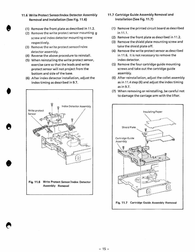
11.6 Write Protect Sensor/Index Detector Assembly Removal and Installation (See Fig. 11.6)
(1) Remove the front plate as described in 11.2. (2) Remove the write protect sensor mou nting g
screw and index detector mounting screw
respectively. (3) Remove the write protect sensor/index
detector assembly. (4) Reverse the above procedure to reinstall. (5) When reinstalling the write protect sensor,
exercise care so that the leads and write protect sensor will not project from the bottom and side of the base.
(6) After index detector installation, adjust the index timing as described in 9.7.
@
Fig.11.6 Write Protect Sensor/ Index Detector Assembly Removal
11.7 Cartridge Guide Assembly Removal and Installation (See Fig. 11 .7)
- 15 -
(1) Remove the printed circuit board as described in 11.1 .
(2) Remove the front plate as described in 1 1.2. (3) Remove the shield plate mounting screw and
take the shield plate off. (4) Remove the write protect sensor as described
in 11 .6. It is not necessary to remove the index detector.
(5) Remove the four cartridge guide mounting screws and take out the cartridge guide assembly.
(6) After reinstallation, adjust the collet assembly as in 11 .4 step (6) and adjust the index timing as in 9.7 .
(7) When removing or reinstalling, be careful not to damage the carriage arm with the lifter.
Insulating Paper
Shi,'dPlot, ~ ~,t--'
Cartridge Guide Assembly
~ <::i\ I
I
Fig. 11.7 Cartridge Guide Assembly Removal

11.8 Stepper Motor Assembly Removal and Installation (See Fig . 11 .8)
(1) Remove the insulating paper and shield plate.
(2) Remove the track 00 sensor as described in
11.3. (3) Remove the two (M2 x 4) actuator screws that
fasten the actuator to the carriage a rm assembly.
(4) Remove the two (M3 x 6) stepper motor assembly mount ing screws and then the stepper ·motor.
(5) Reverse the above procedure to reinstall. (6) After reinstallat ion, perform limiter check as
in 9.10 and radial alignment adjustment as in 9.5.
(7) Adjust the track 00 sensor according to the instruction in 9.8.
Fii- " .8 Stepper Motor Assembly Removal
- 16 -
11 .9 Carriage Arm Assembly Removal and Insta llatio n (See Fig.11 .9)
(1) Remove the printed circuit board as described in 11 .1.
(2) Remove the insulating paper and shield plate. (3) Remove the track 00 assembly as descr jbed in
11.3. (4) Remove the stepper motor assembly as
described in 11 .8. (5) Remove the two guide rod clamp mounting
screws. (6) Remove the carriage arm assembly, guide
rod damp, and guide rod. (7) Pul lout the guide rod from the carri age arm
assembly. (8) Reverse the above procedure to reinstall. (9) After replacement, perform limiter
adjustment as described in 9.10, track 00 sensor adjustment as described in 9.8, and radial al ignment adj ustment as desc ribed in 9.5.
Gu~e R.'~C-_____ . __ ~'
Fig. " .9 Carriage Arm Anembly Removal

•
•
•
•
•
1'.10 Drive Motor Removal and Installation (See Fig.11.10)
(1) Remove the printed circuit board as
described in 11.1 . (2) Remove the insulating paper and shield
plate. (3) Remove the front plate as described in 11 .2. (4) Remove the write protect sensor as described
in 11.6.
(5) Remove the cartridge guide assembly as
described in 11.7.
(6) Remove the three drive motor mounting
screws and take off the drive motor from the base.
(7) Disconnect the drive motor connector pins
from t he connector. (8) Reverse the above procedure to reinstall . (9) When reinstalling, make sure that the drive
motor connector is connected in the correct direction.
(lO)After reinstallation. perform motor speed adjustment as described in 9.' and also the
adjustments necessary upon reinstallation of
the cartridge guide as described in 11 .7.
Drive Motor
Fig. 11.10 Drive Motor RlHTloMi
-17-
11." LED Assembly Removal and Installation
(1) Remove the clamp handle and front plate.
(2) Disconnect the connectors J8 CON from the
printed circuit board.
(3) Remove the lED Assembly by sliding it aslant
from the Cartridge Guide Assembly.
(4) Reverse the above procedure to reinsta ll.
LED Assembly •
Fig.11." LED Assembly Removal

12. TEST POINTS
Printed Circuit Board
(Top view)
GND lNTTRK00
Vout(-) Vout(+) + READ DATA
STEP
- 18 -

13. EXPLODED VIEW
•
•
•
•
• <'r, ~:-.-~w ~\-'=="'~~ ,L_~'
~---\----./ @!
- 19 -

14. REPLACEMENT PARTS LIST
MODEL: JU·455·5
Ref. No. Part No. Description Per Set (pes.)
1 YTF3lQ1901Bl Base 1
2 YTF5W00152B2 Front Panel 1
3 YTF6A01090B3 Clamp Handle 1
4 YTFMOO0790B4 Drive Motor 1
5 YJ617612 Faston 1
6 YTUF56TRK-2T Sensor Assembly (For TRK0) 1
7 YTF2TQ1560B4 Bracket (For TRKeI) 1
B YTF2E02561 B4 Guide Rod 2
9 333046331360 Clamp (For Guide Rod Head) 1
10 YJF2EOOSBOB4 Clamp (For Guide Rod End) 1 11 YTUF55HO Head Carriage Assembly 1
12 YTF2H03582B3 Shield Plate 1
13 YTF2P03591B4 Insulating Paper 1 14 YTUFSSPK·S PCB Assembly 1 15 YTUfS5CG Cartridge Guide Assembly 1 16 YTF3C02732B3 Ufter 1 17 YTF4H0136Q84 Lift Shaft 1 1B YTF4J0190184 Lift Spring 1 19 333046817500 Pat 1 20 YTUFS6ClT2AN Collet Assembly 1 21 UF45CP3CAE1 Clamp Assembly 1
" YJF4 FOO341S2 Clamp Bearing 1 23 YTF4HOl720B3 Clamp Cam Assembly 1 24 333036817692 Lock Cam 1 25 333046624770 Lock Spring 1 26 YTU F45WP4AAA Write Protect Assembly 1 27 YTUF45LED LED Assembly 1 28 YTUF55SM Stepper Motor Assembly 1 29 YTF1G00500B4 Cord Clamp 1 30 YTF1EOO300B 4 Washer Head Screw ' 2 31 XSB2 + 4V Screw (M2x4 Bind) 2 32 XSB3 + 4V Screw (M3x4 Bind) 2 33 XSB3 + 6FX Screw (M3x6 Bind) 11 34 XSB3 + 6V Screw (M3x6 Bind) 1 35 XWC3B Toothed lock Washer 1 36 XYN3 + F6 Screw (M3x6 Sems) 4 37 Y-1283 Screw (M3x6 Bind) 3 3B XUC3 Retaining Ring 1 39 XUC2 Retaining Ring 1
Caution: ,. PCB Assembly is produced to order during the production period only. 2. When you order the aforementioned parts, be sure to specify "Part No." of
the parts ordered.
- .,,, -

•
•
•
•
•
15. REPLACEMENT PARTS LIST OF PCB
MODEL: JU·455·5 Component Side (Top)
Ref. No. Part No. Description .. ER05lTJ6S1 Carbon Resistor
C1 ECEA1HKS1 OOE Electrolyte Capacitor
(2,3.5 FCJOOO8084OQ Ceramic Capacitor
e. ECEA1HKS01OE Electrolyte Capacitor
eN FJCOOO80B400 Connector
eN FJCOOO80B4Ql Connector
eN F KOO0908402 Connector
eN' YJl12294.' Connector
eN' YJ172296·' Clamp
eN' YTFFC4TLBW18 Connector
eN' YJFJCOO 230B4 Connector
eN' YTFFC2l8W1 8 Connector
eN' FJCOO180B400 Connector
1R 1 EXBRB7151JW Block. Resistor
'" EXBP84472J Block Resistor
'" EXBlB5368J Block Resistor
'" EXBG883595 Block Resistor
L FNCOOO308426 Low-FreQuency Coil
L YJBlO2RN2R62 Cnoke Coil
L5 FNCOOO308418 Low-Frequency Coi l
L6 ELEPG330KA CnokeCoil
L9 LAL03KH 101 K Cnoke Coil
VR EVMQOGOl KB24 Variable Resistor
X YJCSA4.00MG Resonator
16 DN74LS16-1S Ie
" DN74LS38-1 Ie
p FJPOO110B40Q Plug
XV YJOILB14P8JC Ie Socket
HA1342 HA13421 L51 1
HA1664 HA16642MP 1e ,
:QLOOO FQLQOO8184 L51 8
Solder Side (Bottom) Per Set Ref. No. Part No. Description (pes.)
1 Rl,2,3 FRAOOO1OB428 Chip Resistor
1 R' FRAOOO40BII32 Chip Resistor
3 R8 FRAOOO40B496 Chip Resistor
1 ., FRAQOOSOB4Z0 Chip Resistor
1 RlO.11 FRAOOO4QB477 Chip Resistor , '12 FRAOOQ40B486 Chip Resistor , R13 FRAOOO40B464 Chip Resistor
1 "'0 FRAOOQ408472 Chip Resistor
1 ",1 FRAOOO40B442 Chip Resistor
1 R2l,Zl, 24,25, FRAOQQ4QB470 Cnip Resistor
1 27
1 '28 FRAOOO40B478 Cnip Resist or
1 R29 FRAOOO40B468 Cnip Res istor
1 (6,7.24 F(COOO608408 Cnip Ca pacit or
1 CB.9 FCCOOO40B420 Cnip Capacitor
1 Cl0, l '.
1 15.16. FCCOOO208401 CnipCa pacitor 26 , e18 FCCOOO70B409 CnipCapacitor , C19.23 FCCOOOt08440 Cnip Capacitor
1 C20 FCCOOO108456 (nip Capacitor 1 C2S FCCOOO10B444 Cnip Capacitor 1 eNS YTB4B-PH Connector 1
eN' FJCOO220B403 Connector 1 0 MA1S1WK-TW Diode 1 0 MA151WK-TX Diode 1 0 MA159·TW Cnip Diode ,
0 MA1S9·TX Cnip Diode 1
1
1
1
- 21 -
Per Set (pes.)
3
1
1
1 , 1
1
1
1
S
1
1 , , S
1 , 1
1
1
1
S
S
1
1

•
•
•
•
16. SCHEMATIC DIAGRAM (JU-455-5)
-WIRTEDATA
- DRIVE SELECT
-MOTOR ON
-HEAD LOAD
-WRITE GATE - STEP
DIRECTION SIDE SELECT
- INDEX PC
+WPPC + TKOO PC
INDEX PE WPPE TKOO PE
3 W
R2~1 10KJr
HA16642
t-:.';..~t:=======~I : OS ------e~-+-+--~+_~ MTRON
,
• Hl' !'-'L----
• H12I;JL _ _
FQLDaoe
5.

RP6 12V 3SK 2 i"' - - .7K
1 -l l"'l -, ,," .
1 ~I 15
8J I J:C~OV ' iP '''' . '4.7K
25V • 42322 21
DP7 OPZMA151WKb:51
MA159 r;: -'" gCcAI , 18 ,-""1
~z V'> 16 Jr.~ "-:~ ~ ~
~ I~ 7 AI2 19 'z. K Qf'~
~ ~oWT1'2 :;;: 2 N 1
88 8~~ . RP6 DP3l,: .
,8 711 "
'Z.7K .-::' DPo'
R6 1= 680Q1f2W
~p;
TP6
0
-".-
7
5 11
6
"_. "" •
RW10
l·moCT
,
R
RW20
o Rwn
HOlel
W21
E1
, m=GND GND
1 GND -w-L-NC 1 ." 5a'------~L )( 30 -READ DATA
• • 5MD3
" : HEAD LOAD OPTION 03
DM51AZ I I I I I
TP7
± " yt- OMACT 2: -INDEX
sv Rl
)( - TRACK 00 ." 1l9]
- WRITE PROTECT
w-L-osw R' DR
- SV 13 " ~ DRTN
-5V 11
,y 34 -READY
11
"
- 22 -
NOTE :
1. NOT USED R26
12V ____ ___ %'-..L sv W 6 12VCGV)
~INDEXlA ~TKOOLA
",r---~w----L lZVRTN
BEAD.FILTER
5VDC~' L2 5V
TP10 (2 GNO '3 'IIFI25V 1~8K GND 2 (6
IIVDC _'-';1'-~1:o,~,~Ii~k~v~ L1
BEAD.FILTER
~--_ ... lZV

•
•
17. CIRCUIT BOARD
• •
.-~ .
Component Side (Top)
So lder Side (Bottom)
- 23 -

18. BLOCK DIAGRAM
/
-
I~ <:...
~:::'" . .
H IV
;, f~
~ J
, v~ ~ ~
;Q!'l ill (/) ['] <7
g;!::t "l"l m
,,/ "-
1"19 q 'l "I
I ~~~ I~~~ I ~~~ 1~~~~~I~~~~~~~ ~I ~~~~~~ 1 - if •
! • • , ,
~ e D g c 0
~. u ci
r;:::: oj ~
Ir
~. ~ -~. ,
l a~I~1 I ~~I ~~
I I I I -
D-r=l 8 ~
~ ~ !}-reI 1 1 z
[}-- 24 -
I i I
~
•