Pallett, Peter F and Filip, Ray ISBN 978-0-7277-6338 …...25.5.3 Design considerations Similar...
6
Pallett, Peter F and Filip, Ray ISBN 978-0-7277-6338-9 https://doi.org/10.1680/twse.63389 ICE Publishing: All rights reserved
Transcript of Pallett, Peter F and Filip, Ray ISBN 978-0-7277-6338 …...25.5.3 Design considerations Similar...

Pallett, Peter F and Filip, RayISBN 978-0-7277-6338-9https://doi.org/10.1680/twse.63389ICE Publishing: All rights reserved

g Water treatment: purification plant for clean water, sewage treatment plant for
wastewater.g Communications: overhead cables, satellite receiver dish, aerial mast.g Transport links: roadway, airstrip, harbour with quayside, helipad, railway siding,
canal.
3.3. Communications, energy, clean water supply andwastewater disposal
3.3.1 CommunicationsIt is common business practice to provide high-speed internet access on site for all site-
based personnel. Advances in technology for mobile devices means we now only need a
single lightweight hand-held device that can be used as both a laptop and mobile phone.
Figure 3.2 Compound layout for a small site. (Courtesy of Costain)
Position of compoundand high value storage area70 m × 40 m
18 × 11 m × 1.8 mClose board timber fencing
2.4 m Chainlink fencing
2.4 m Chainlink fencing
Position of work areaand fuel storage110 m × 180 m
3 No. 6 mdouble leaf gates
Vehi
cle w
aitin
g zo
ne
Stor
es/sh
utte
r
cons
truct
ion
Lot 1
Are
a(In
dica
tive)
Lot 2
Are
a(In
dica
tive)
1 No. pedestrianaccess gate
Site compounds and set-up
47
Case study 1
COPYRIGHTED M
ATERIAL. DO N
OT DISTRIBUTE
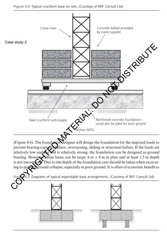
(Figure 4.6). The foundation designer will design the foundation for the imposed loads to
prevent bearing-capacity failure, overturning, sliding or structural failure. If the loads are
relatively low and the soil is relatively strong, the foundation can be designed as ground
bearing. However, these bases can be large: 6 m × 6 m in plan and at least 1.5 m depth
is not uncommon. Due to the depth of the foundation care should be taken when excavat-
ing to prevent ground collapse, especially in poor ground. It is often of economic benefit to
Figure 4.4 Typical cruciform base on rails. (Courtesy of RKF Consult Ltd)
Concrete ballast providedby crane supplier
Section (NTS)
Reinforced concrete foundation –could also be piled for poor ground
Steel cruciform with bogies
Crane mast
Figure 4.5 Diagrams of typical expendable base arrangements. (Courtesy of RKF Consult Ltd)
Tower crane bases
63
Case study 2
COPYRIGHTED M
ATERIAL. DO N
OT DISTRIBUTE

to apply (because these support systems are relatively flexible and there is a degree of soil
arching and displacement which leads to a redistribution of pressures). From full-scale
tests, Terzaghi and Peck (1996) derived empirical trapezoidal pressure diagrams for
calculating maximum strut loads. From further experience, these pressure diagrams were
Figure 12.5 (a) Post and plank excavation and (b) side rail system trench. (Courtesy of GroundforceShorco Ltd)
Trenching
169
Case study 3
COPYRIGHTED M
ATERIAL. DO N
OT DISTRIBUTE

It is also essential that the site team understands the limitations of the plant use on the
barge or pontoon, and does not stray outside of the boundaries set. Any required
changes to site operations should be referred back to the designer to confirm it is safe
to proceed.
As well as cranes, excavators can also be used on barges for such activities as dredging or
grading of river banks or for positioning of bank protection such as rip rap (large
stonework). An excavator working is more dynamic than a crane and the pontoon can
experience more roll, which can make working difficult. In these circumstances, the
barge may be fitted with ‘spud legs’, which are generally circular tubes running through
the deck of the pontoon. These can be lowered so they embed into the river bed to
provide extra stability (Figure 18.2).
Care does need to be taken when using spud legs purely for stability if the watercourse is
subject to wave action or the pontoon is operating during an ebb tide. The reason for this
is that in either scenario an air gap could appear below the pontoon, meaning its weight
is transferred onto the spud legs rather than being supported by the water. If the pontoon
has not been designed for this scenario it could either become unstable or individual
elements could fail due to the change in load path.
If any of the above scenarios could occur a jack-up barge may be more appropriate (see
Section 18.2.3).
Figure 18.1 Typical barge with crane and ancillary plant
Floating plant
241
Case study 4
COPYRIGHTED M
ATERIAL. DO N
OT DISTRIBUTE

Screens can be clad in either solid panels (e.g. plywood) or perforated mesh or netting,
and are supported on rails attached to the already cast slabs of the permanent structure.
Commonly, perforated panels or mesh is chosen as it provides a balance between
reducing the imposed wind load, while protecting those below who may be struck by
falling debris, but still permitting natural light to enter each working level. Screens can
incorporate working platforms for essential work such as post-tensioning operations or
to provide space for following trades undertaking work on the facade. Some screens are
simple barriers without platforms, but do have folding covers to prevent debris falling to
lower levels.
25.5.3 Design considerationsSimilar criteria to those examined when determining the suitability of a climbing form-
work system are applicable when deciding on the suitability of a protection screen
Figure 25.7 Typical protection screen sections. (Courtesy of Hunnebeck (a BrandSafway company))
Three platforms(2 deep + 1 wide)
Single cantilever
Four platforms(3 deep + 1 wide)
Single cantilever
Four platforms(2 deep + 2 wide)
Double cantilever
Dry Dry Dry
Dry Dry Dry
Wet Wet Dry
Wet Wet
Climbing and slip forms
365
Case study 5
COPYRIGHTED M
ATERIAL. DO N
OT DISTRIBUTE