PALIGHT Fabrication Guide - Palram Americas
20
PALIGHT ® Foam PVC Panels Fabrication Guide
Transcript of PALIGHT Fabrication Guide - Palram Americas

PALIGHT®
Foam PVC Panels
Fabrication Guide

Some Foam PVC products manufactured by others may contain lead. Palight is manufactured without lead or any other heavy metal.
While Palram has manufacturing facilities in Israel, China, U.K. and the USA, the majority of products sold by Palram Americas are manufactured in Kutztown, PA, USA.
Overview of the PALIGHT Product Line:Palram is one of the world’s largest producers of Free-Foam PVC Sheet products. The table below is provided to help you understand which Palight products are available and how they differ, so you can be sure you’re choosing the right product for your application.
Application & Product Print, Graphics, and Display Marine Construction
Feature PALIGHT Premium
PALIGHT EPS
PALIGHT Outdoor
PALIGHT Marine
PALIGHT Trimboard
ColorsBrightest White* &
Array of ColorsWhite* White* White*
White*, Sand, and Clay
Protective FilmPalight (1-Sided) Palight DF (2-Sided)Palight NF (No Film)
Not Available Not Available Not Available 1-Sided
Weight, Density, and Rigidity
Very Good Good Very Good Very Good Very Good
Available Dimensions
Widest Variety Limited Variety Limited Variety
UV ProtectionAcceptable
(applies to white only)Limited Ideal Limited Ideal
Intended Use High quality signs, graphics, displays and exhibits.Provides the best all-around performance for digital & screen print applications, and display fabrication.
An Economical Print Substrate (EPS). Great for lamination applica-tions and cost-sensitive or short-term use digital and screen print applications.
Signs and displays destined for long-term outdoor exposure. Available in smooth or wood grain finish. Available in dimen-sions that are suitable for outdoor use.
Intended for marine or motor home appli-cations. Seat backers, cabinet partitions, etc.
Used in home con-struction as a wood replacement for interior or exterior trim moulding. Sold in typi-cal trim board/lumber dimensions, as well as full-size sheets .
*Each white color is specifically formulated per market segment.
As depicted here, PALIGHT® Premium Foam PVC is available in
a broad range of thicknesses. A wide variety of colors are also
available. Other variants of PALIGHT are available for specific
applications, including PALIGHT EPS, Outdoor, and Trimboard.

Introduction to Palight 1
Features and Benefits 1
Cutting 1
Drilling 1
Milling 2
Routing 2
Thermal Expansion / Contraction 2
Screwing and Nailing 2
Installation 2
Exterior Signs 3
Tips on Sign Installations with Posts 3
Significant Items to be Considered 3
Screwed Joints 3
Riveted Joints 3
Frame Fastening of Flat Palight Sheets 3
Hanging Signs 3
Adhesive Bonding of Palight 4
Heat Bending 5
Thermoforming 5
Heating Cycle 5
Processing Temperatures 6
Painting 7
Graphic Applications 8
Direct Digital Printing 9
Laminating 9
Chemical Resistance 12
PSDS Information (Replaces MSDS) 16
Recommended Uses and Restrictions 16
Further Information 16
Physical Properties Table 16
Contents

1
Introduction to PalightPALIGHT foamed PVC sheet is versatile, flexible, lightweight, and durable and is ideal for use digital or screen printing, fabrication, and construction.
PALIGHT Premium Foam PVC exhibits the whitest color available and has been successfully tested and approved by digital flatbed printer manufacturers worldwide. Printers and display builders will benefit from its consistent, smooth, and bright surface for producing high quality displays.
PALIGHT is easily handled, cut and fabricated using conventional tools and equipment, and can be printed, painted or laminated.
Features and Benefits§§ Ease of Fabrication
§§ Light Weight
§§ Chemical Resistant
§§ Superior Insulating Characteristics
§§ Moisture Resistant
§§ Great Flammability Ratings
§§ Heavy Metal Free
§§ Manufactured in the USA, Israel, and U.K.
CuttingCircular Saws PALIGHT material up to 3 mm thick can be cut with a knife or blade.
For Palight sheets 3 mm and thicker, carbide-tipped, triple chip, ground type circular saws can be used. The following settings are recommended:§§ Rake angle: 0 to 15
§§ Clearance angle: 10 to 20
§§ Cutting speed: 4,000 to 8,000 feet per minute
§§ Feed: 70 to 90 feet per minute
§§ Tooth pitch: 0.080” to 0.040”
§§ Band Saws
High speed steel blades normally recommended for wood or plastic can be used for Palight material utilizing the following guidelines.§§ 6 to 8 teeth per inch
§§ Cutting speed: 3,000 to 5,000 feet per minute
§§ Feed: up to 40 feet per minute
Saber Saws Rough cut type blades ground for plastics can be used on Palight sheets. Smooth metal-cutting blades are not recommended.
DrillingPalight can be drilled with carbide-tipped bits using twist drills recommended for metals.
The following settings are recommended:§§ Point angle: between 90 to 110
§§ Spiral angle: 30
§§ Relief angle: 10
§§ Cutting speed: 150 to 1,300 feet per minute
§§ Feed rate: 0.01 to 0.02 inches per revolution
The minimum distance from the edge should be 2 times the hole diameter In an effort to reduce heat build up during drilling of thicker Palight sheets, it may be necessary to periodically remove the drill bit from the Palight material.

2
MillingPalight can be milled by using standard milling machines of various types utilizing the following guidelines:
§§ Relief angle: 5 to 10
§§ Rake angle: -10 to 0
§§ Cutting speed: 3,000 to 3,500 feet per minute
§§ Cutting feed: 0.12 inches per revolution
RoutingPalight material can be easily routed using multi-fluted carbide tools on standard woodworking routers. Standard tools and machines can be utilized with no need to alter equipment. Adjust feed and speed rates as needed to achieve the best edge finish on the Palight parts.
Thermal Expansion / Contraction As with most plastics, Palight foamed PVC will expand and contract with an increase or reduction in temperature. This material property is known as linear thermal expansion and contraction.
Since Palight can be used in a wide variety of indoor and outdoor applications, linear thermal expansion and contraction may need to be considered during the fabrication and installation of the material. It is important to take in to account the temperature at which the Palight material was fabricated as well as the temperature of the installation.
Palight should not be used in applications or climatic conditions that exceed 140° F (ambient or surface temperature), at which temperature the Palight will soften and permanently deform. Dark colors are generally not recommended for outdoor use, as they absorb heat and can easily exceed the maximum allowable temperature of 140° F.
Palight Linear Expansion / Contraction Quick Reference
Total Temp. Change (∆)
Expansion / Contraction of Material at Standard Lengths / Widths (in inches)
48 in. 60 in. 96 in. 120 in.
20°F 0.036 0.044 0.071 0.089
40°F 0.071 0.089 0.142 0.178
60°F 0.107 0.133 0.213 0.266
80°F 0.142 0.178 0.284 0.355
100°F 0.178 0.222 0.355 0.444
120°F 0.213 0.266 0.426 0.533
140°F 0.249 0.311 0.497 0.622
Screwing and NailingAny type of screw or nail can be used to fasten Palight material. Power nailers and screw driving equipment are suggested. Inserting the screw or nail in an elongated slot or an oversized hole is recommended so that the material can expand or contract if fluctuations in temperature occur. For best results, use oversized washers or grommets in combination with screws.
InstallationPalight is manufactured as an extruded foam PVC product with a directional grain running the entire length of the sheet. This manufacturing process gives Palight greater flexural strength in the direction of the extrusion. The grain of the Palight should always be installed perpendicular to the fastening point.
Distances Between Fastening Points for Screw and Rivet Joints
Sheet Thickness Distance Between Fastening Points
2 mm 6 - 8 in.
3 mm 12 -16 in.
4 mm 20 -28 in.
5 mm 31 - 43 in.
6 mm 47 - 70 in.
3
Exterior SignsPalight, when used correctly and with basic mechanical fixing methods is suitable for exterior use. Using Palight can provide an excellent weatherproof sign substrate ready for screen printing, painting, or vinyl graphics.
Tips on Sign Installations with PostsThe following tips have been compiled to be used as a general guide for fixing Palight for a minimum amount of breakage.
Unusual designs falling outside the examples given may require certain modifications when considering Palight.
Significant Items to be Considered1. Bolt holes should always be larger than the bolt shaft to allow for thermal expansion and contraction, thus eliminating the possible
stress at bolt fixing points. The use of washers spread the compressive load when bolts/nuts are tightened. Be sure not to over tighten as this will weaken the connection.
2. Split timber posts are the best to use because the Palight is supported evenly on both sides. If steel or aluminum poles are used, nylon bolts and washers give the best results. Be certain not to skimp on fasteners for these types of installation. They should be evenly spaced and away from the top and bottom edges.
Screwed JointsFor the attachment of Palight, basically all known through bolts are acceptable. For outdoor mounting, it is recommended that the bolt shank be passed through the PALIGHT in prepared holes or suitably dimensioned slots that leave adequate clearance between the bolt shank and the Palight.
The screws should only be tightened firmly enough to allow the sheet to expand and contract in all directions without warping or buckling. Tapping screws or screws with form fitted passage of the shank through the sheet should be avoided, but are allowed for interior uses with predictably low temperature variations.
The diameter of the hole or length of the slot should not be less than 2.5 times the shank diameter of the fastener. Disc washers should be used to cover the holes or to bridge the slots and they should be large enough to ensure adequate load distribution. Precise centering of the screws in holes and slots is essential to permit free movement of the sheet in all directions.
Riveted JointsThe same measures that are used for screwed joints also apply to riveted joints. For this reason full rivets, whose shaft enlarges during the clenching operation so that the clearance to the hole diameter diminishes, are not suitable for outdoor mounting of Palight. Blind rivets (pop rivets) are suitable for fastening Palight to metal bases which are mounted by the drawing of aluminum or the steel mandrel.
Frame Fastening of Flat Palight SheetsPalight can be fastened utilizing various different framing materials such as, but not limited to, wood, aluminum, steel and vinyl. Besides the inherent rigidity of Palight sheets, which is dependent on thickness, all possible exterior stresses, e.g., wind pressure, etc., must be taken into consideration in frame fastening. For appropriate mechanical and elastic property values the data sheet should be consulted. Dimensional changes due to thermal expansion (or contraction) must be taken into consideration by leaving sufficient clearance between the sheet edge and the frame.
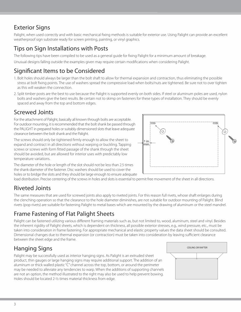
Hanging SignsPalight may be successfully used as interior hanging signs. As Palight is an extruded sheet product, thin gauges or large hanging signs may require additional support. The addition of an aluminum or thick walled plastic “C” channel across the top, bottom, or around the perimeter may be needed to alleviate any tendencies to warp. When the additions of supporting channels are not an option, the method illustrated to the right may also be used to help prevent bowing. Holes should be located 2-1/2 times material thickness from edge.
CEILING OR RAFTER
1 in.min.

4
Adhesives and ManufacturersThe table below lists several adhesives and their bonding applications for materials commonly used in fabricating Palight products. The listed adhesives and manufacturers are for informational purposes only. Please perform the appropriate tests to ensure that the materials will produce desired results.
Adhesive Manufacturer Phone / Website Adhesive Type Palig
ht M
ater
ial
Alu
min
um
Woo
d
Mas
onry
Acr
ylic
Plas
tics
Gal
vani
zed
Stee
l
Poly
styr
ofoa
m
Tetrahydrofuran (THF) ISP Technologies 973-628-4000 Solvent ✔
IPS Weld-on 2007 IPS Weld on 310-898-3300 Solvent Mixture ✔ ✔ ✔
PVC Pipe Cement Multiple Mfgs. Solvent Mixture ✔ ✔
TACC 15-165 TACC International 781-878-7015 Synthetic Rubber ✔
Scotch Grip Plastic Adhesive 4475
3M 800-362-3550 Solvent Mixture ✔
Liquid Nails LN 602 Liquid Nails 800-634-0015 Synthetic Rubber ✔ ✔ ✔ ✔ ✔ ✔
Parabond P28 Cement Parabond 800-763-7272 Solvent Mixture ✔ ✔ ✔
DOW 795 Silicone Dow Corning www.dowcorning.com Silicone ✔ ✔ ✔
Bostik 4045 Bostik Corporation www.bostik-us.com Solvent Mixture ✔
Adhesive Bonding of Palight General Information Palight material can readily be bonded to itself or other materials. Commercially available adhesives that are suitable for bonding rigid PVC materials can be used for this purpose.
There are several considerations when choosing an adhesive:
1. The material to be bonded with Palight
2. Strength required—structural vs. non-structural
3. Temperature range expected
4. Expansion/contraction
5. Ease of application methods, curing times
6. Cost effectiveness
7. Environmental and safety considerations—flammability, fumes, odors, etc.
Surface Preparation In order to attain the optimum bond, the Palight material surfaces to be bonded must be cleaned and degreased using a white cloth soaked in isopropyl alchohol.
Selection of Adhesives
The selection of the proper adhesive for a project depends on the materials to be joined, as well as the end use and other considerations mentioned previously.

5
The following suggestions serve as general guidelines:
A. Bonding Palight Material to Palight Material
1. For edge bonding and joining parts made of Palight material, use a PVC solvent such as (THF, MEK, cyclohexanone solvent systems).
2. For bonding large areas: If using PVC solvent such as pipe cement, spread with notched trowel and work rapidly.
B. Bonding Palight Material to Non-Porous Solid Material (such as PVC, other plastics or metal):
1. Contact adhesive with solvent:
a. Neoprene, nitrile, polyurethane or other synthetic rubber types.
b. Adhesive must be applied to both faces. Parallel beads of adhesive are often preferred because it allows evaporation of solvent providing faster cure.
c. Use a slow setting adhesive, when bonding large areas. This allows for more time to properly install the panels prior to the adhesive curing.
d. For bonding Palight material to flexible PVC sheets, only plasticizer-resistant types of adhesives should be used.
C. Bonding Palight Material to Porous Materials (such as paper, textiles, fabrics or wood).
1. Contact adhesive with solvent: Same systems as for non-porous materials.
2. Construction mastic, structural silicone adhesives.Considerations such as expected temperature ranges (expansion/contraction), substrate and size of Palight material panels should be taken into consideration when deciding on a method of attachment.
Heat Bending Palight sheet material can be bent by using Calrods, radiant heaters, strip heaters or air-circulated ovens. Heat guns can also be used on small areas. To ensure best results, a rheostat should be used to control heating of the Palight so that the surface temperature does not exceed 340˚ F. Heating Palight material over 340˚ F can cause the surface to become rough and possibly discolor.
When using a metal contact strip heater, cover the heater strip with Teflon spray to prevent marking the Palight. Different sizes of rectangular heating bars can be used to produce bends of different radii. The larger the heated area of the Palight, the larger the radius that can be created. Palight should be heated from both sides when the sheet is thicker than 4 mm. Palight requires heating at the rate of approximately 30 to 40 seconds per millimeter of thickness prior to bending.
To form tighter bends with smaller radii, use a small heated area on the upper surface (inside the bend) of the Palight sheet and a larger heated area on the bottom surface (on the outside of the bend) of the sheet. A minimum radius of twice the sheet thickness is necessary to avoid breakage. When bending Palight into an angle, typically the extension of the Palight on either side of the angle should be at least 20 times the thickness of the Palight material.
For example, 6 mm (1/4”) Palight would require the extension on each side to be 120 mm (4-3/4”) in order to avoid warping of the material. For sides less than 20 times the material’s thickness, the entire sheet must be heated. Once the Palight is bent, place it in a fixture, such as a jig or clamp, to cool. Fans and/or compressed air will speed the cooling process.
ThermoformingPalight is a slightly expanded thermoplastic sheet material which may be thermoformed by all conventional methods and techniques. Standard machines used for thermoforming work with Palight. With regard to forming capability, extensibility, and detail definition, Palight has certain limitations. The air entrapped in the closed cells cannot be plasticized by the heat and can affect the molding and stretching of the sheet. Palight is most suitable for large-faced and smoothly-contoured parts. Draw ratios between 1:1 and 1:1.25 are readily attainable with Palight. Larger ratios can be accomplished with auxiliary equipment such as plug assist or pressure assist forming. The radius and depth of draw is generally limited to the extent that the surface of the material can stretch. Palight does not need to be dried prior to forming, assuming it is stored indoors and properly sheltered.
Heating CycleBecause Palight is moderately expanded, it reacts differently than solid plastic materials and the working cycle is generally shorter. Small panel ceramic or quartz sandwich heaters are the most efficient type of heating. Care must be taken to not overheat the surfaces during the heating cycle in order to avoid degradation. For more uniform temperature distribution, preheat Palight in a circulating air oven at 140° F.

6
Processing Temperatures
Thermoforming Processing Temperature Range For Palight
1 2 3 4 5
Mold & Set Temp. Lower Processing Limit Orienting Temp. Normal Forming (core) Temp. Upper Limit
ºF ºC ºF ºC ºF ºC ºF ºC ºF ºC
115 46 240 116 260 127 275 135 350 177
Mold and Set Temperature: 1
The set temperature is the temperature at which the sheet hardens and can be safely removed from the mold. The closer the Mold temperature is to the Set temperature, the smaller the chance of encountering internal stress problems.
Lower Processing Limit: 2
This is the lowest temperature possible for the sheet before it is completely formed. Material formed at or below this temperature could have severely increased internal stresses that later can cause warping, and lower impact strength.
Orienting Temperature: 3
Biaxially orienting the molecular structure of thermoplastic sheet approximately 275% to 300% at these temperatures and their cooling greatly enhances properties such as impact and tensile strength.
Normal Forming Temperature: 4
This is the temperature which the sheet should reach for proper forming conditions under normal circumstances. The normal forming temperature is determined by heating the sheet to the highest temperature at which it still has enough strength to be handled, yet below the degradation temperature.
Upper Limit: 5
The Upper Limit is the temperature at which the sheet begins to degrade or decompose. It is crucial to ensure that the sheet temperature stays below this temperature.
Additional Thermoforming Tips
Palight material, provided it is stored indoors or properly sheltered, need not be dried before forming. Unlike ABS and polycarbonates, Palight material does not absorb any hydroscopic moisture.
Plug-assist forming, using normal equipment, is necessary for more complicated shapes. Because of the lower heat capacity of Palight material, low conductivity materials must be used for the plug.
Molds must be designed to facilitate ready flow of material. Sharp edges and narrow recesses should be avoided. Radii should not be less than 1.5 to 2 times the original sheet thickness.
Double-sided (sandwich type) heating is strongly recommended, especially for thicker sheets, Palight material of 3 mm gauge and thicker can be thermoformed only with a double-sided heating arrangement.
When heated above 140° F, sheets shrink slightly in the extrusion direction. Provide for the firm clamping down of sheets or for controlled slip-in.
When thermoforming colored Palight material, deep draws combined with sharp radii may cause stress whitening, as with
most PVC materials.

7
PaintingThe painting of Palight is easily accomplished with paints known to have compatibility with rigid PVC.
Selection of a paint system for each use should be guided by the following:
1. Cost effectiveness.
2. Ease of application.
3. Safety and Environmental — odor, solvent systems, toxicity, etc.
4. Convenience and speed — one part vs. two part, one coat vs. multiple coats.
5. Solvent and/or chemical resistance.
6. Outdoor weatherability & reflectance value. (When painting Palight with darker colors, for use in exterior applications, it is imperative that the paint has a light reflectance value of 55 or higher in order to avoid excessive heat absorbtion, which will result in distortion of the Palight.)
I. Types of paints known to be compatible with Palight sheet
A. Vinyls
B. Acrylic Lacquers
C. Two part polyurethanesWith Palight, water-based latex systems and oil-based enamels generally do not have the good adherence properties of solvent based systems. Although, the use of primers can improve the adherence of non-solvent based systems, the adherence is usually minimal.
II. Surface Preparation
A. The surface to be painted must remain dry, clean, and grease free.
B. Any surface scratches on Palight will have a tendency to telegraph through the paint. In order to remove small scratches or dents, rapidly fan a heat gun over the affected area. Care must be taken not to leave the hot air in one place for too long, as the surface can be deformed.
C. It is highly recommended that the surface be cleaned with a rag moistened with isopropyl alcohol prior to painting.
III. Adhesion Test
A. The paint system chosen should always be tested for adequate adhesion. To test for adhesion, conduct the Cross Hatch Test after the paint has dried for at least 24 hours.
1. Make eleven parallel cuts 1/16" apart with a razor blade knife. Make eleven similar cuts at 90 degrees to cross the first set.
2. Across the scored area apply a strip of strong tape, such as #610 Scotch tape. Press firmly.
3. Immediately remove the tape by pulling it back upon itself at 180 degrees in one rapid motion.
4. There shall be no removal of the paint squares to obtain a good adhesion rating.
IV. Application
A. Paints can usually be applied with a brush or roller, although conventional air spray equipment will provide a more consistent appearance.
B. Consult paint manufacturer’s literature for recommended application technique and thinning requirements.
V. Drying
Palight is a thermoplastic material. It should not be dried at temperatures in excess of 140° F. For drying and cure times, consult paint manufacturer’s literature.
CAUTION: Due to the wide variety of paint products on the market, and the fact that some paints have been known to embrittle or bow Palight, testing is recommended for the initial use of any coating system before commercialization.

8
Graphic ApplicationsPalight performs superbly in a wide range of graphic applications including those involving paints, screen printing, digital flatbed printing and vinyl films. Palight can be used to create weather-resistant signs, displays or Point of Purchase (POP) materials. The smooth Palight surface is ideal for all types of graphics, and it requires little surface preparation or surface treatment.
General Considerations
To ensure best results for any graphic application using Palight, consider the following factors that may affect the finish installation:§§ Environmental and safety concerns
§§ Weathering
§§ Chemical resistance
§§ Ease of application
§§ Cost-effectiveness
§§ Hardness
§§ Scratch resistance
§§ Priming or multicoat paint applications
TIP: Because of the wide range of products available, select paints carefully for each application. Initial testing of the selected paint system is recommended before a production run.
Cleaning / Pretreating
Before screen printing or painting Palight, the surface area should be cleaned with isopropyl alcohol and a clean white cloth. Depending on the specific application, certain pre-treatments may also be required, as described in the following sections.
Screen Printing
With Palight, the process of Screen Printing is easily accomplished. The surface of Palight has a closed cell matte finish that makes mistakes easily wipe off with the appropriate thinner.The use of Vinyl and Vinyl/acrylic, solvent based inks are very compatible with Palight.
The use of Water Based Screen Printing Inks has also had some success with Palight material. Ink manufacturer directions must be followed for good adhesion. Surface preparation of Palight for screen printing is similar to those of painting.
A. The surface to be screen printed area must remain dry, clean, and grease free.
B. Any surface scratches on the Palight will have a tendency to shadow through the ink. In order to remove small scratches or dents, rapidly fan a heat gun over the affected area. Care must be taken not to leave the hot air in one place for too long, as the surface can become deformed. It is highly recommended that the surface be cleaned with a white cloth moistened with isopropyl alcohol prior to printing.
All screen printing inks should be tested in a manner which duplicates your printing process before initiating production. It is strongly recommended to consult the appropriate ink manufacturer regarding any required ink additives such as catalyst for proper adhesion and exterior usage. Screen Printing ink should air dry, rather than be heat dried. Temperatures in excess of 140° F may cause warping or bowing of Palight material.
Most UV Screen Printing Inks that are compatible with rigid PVC will work on Palight. The most important factor to be considered when using UV systems is the curing oven. Low wattage bulbs should be used to keep the temperature below 140° F. The use of UV curing systems, which have variable speed conveyors, are considered the best type to use with Palight.
Please consult the following ink manufacturers regarding the recommended inks to be used with Palight foam PVC.
Fujifilm Sericol USA, Inc. 1101 W. Cambridge Dr. Kansas City, KS 66103 913-342-4060
NazDar 8501 Hedge Lane Terrace Shawnee, KS 66227-3290 913-422-1888

9
Direct Digital PrintingGrand format and flatbed printers use various ink and ink curing technologies to allow high quality printing at relatively high speeds. High quality digital printing depends on various factors: §§ Printer capabilities
§§ Ink technology and quality
§§ Type of printing substrate and quality
§§ Machine operator
PALIGHT’S bright whiteness enables printers to print directly on it and achieve accurate, consistent color values and brightness.
PALIGHT is suitable for use with UV curing and solvent-based digital inks, and for IR drying when water-based inks are used.
PALIGHT retains superb whiteness, even after intense UV curing.
Protective Film Masking
The protective polyethylene film mask helps prevent surface abrasion and stains. However, removing the protective film may cause an increase of static electric charge, which can affect ink coverage. Therefore, after peeling the film away from the sheet, the static electricity that has built up in the sheet should be discharged using an ionized gun or a suitable device provided by the printer manufacturer.
Cleaning PALIGHT and Preparing for Printing
The surface should be clean before printing. Carefully inspect each panel to ensure there is no: dust, fingerprints, residue or other problematic substances that may affect ink coverage or adhesion. If needed, the PALIGHT should be cleaned with a damp rag, or with isopropyl alcohol.
Ink
PALIGHT is suitable for all types of inks: Aqueous, Solvent-Based, and UV-curable. In fact, PALIGHT has been tested and approved by major printer OEM’s around the world, including AGFA, Gandinnovations, HP, Mutoh, Océ, and more. Consult the printer manual or contact the printer manufacturer for recommendations and compatibility information.
Drying the ink
The two main drying technologies are:
IR (Infrared) – Long exposure to high temperature in the drying tunnel may cause distortions in the sheet.
UV (Ultraviolet) – UV levels must be adjusted according the printing speed and substrate. UV overexposure can cause discoloration of both the ink and substrate.
Print Head Adjustment
The distance between the print head and the substrate can have a significant effect on print quality. Manufacturer specifications, combined with and operator experience, should determine print head distance from the substrate.
The suggested starting distance should not be more than 2 mm from the print head to the substrate.
LaminatingPalight is an ideal material for applications that require lamination. This section provides preparation information processes as well as detailed instructions for the various types of lamination that can used with Palight. Because prints are one of the most frequently laminated materials, the sections that follow will generally refer the lamination of a print, although many other materials can be used.
NOTE! Because Palight material may warp when heated above 140°F or when heated from one side only, it cannot be used in any lamination process requiring heat.
Adhesion
For best results, the Palight material should be cleaned with isopropyl alcohol prior to adhesion and allowed to dry thoroughly. When laminating with pressure-sensitive adhesives, a force of 25–40 psi is required. Proper spacers are also critical. Because force must be applied equally across the material, the top roll must move evenly from left to right while maintaining even contact between top and bottom laminating rolls. To achieve even contact, “zero the nip,” then use spacer shims to preset the nip opening for a particular laminate. Use sufficient pressure to completely eliminate any air bubbles between the Palight material, the adhesive and the print or other material.

10
The lamination will achieve maximum bonding in three hours. If the lamination has been performed properly, the finished mount can be flexed without the print becoming loose in the center. To prevent moisture from becoming trapped between layers of porous material (such as paper) and creating blisters, the level of moisture in both the material to be laminated and the atmosphere should be reduced before pressing. Some materials may require pre-drying. Palight is nonporous and does not need pre-drying.
Preventing Surface Blemishes
Surface blemishes, such as wrinkles, can be caused by misalignment of the adhesive roll or too much pressure or rollers that are not parallel. Trapped dirt or lumps of hardened adhesive common with glossy prints may create small bumps in the finished product. In order to prevent these problems, equipment used for Palight lamination must be kept clean. Use a fresh roll or sheet of transfer adhesive if bumps are caused by hardened adhesive. Dirt problems can be minimized by using an ionizing static eliminator. Using prints or other materials made with a paper 0.007” or thicker can help prevent strike through.
For best results, wipe down the back of the print and the face of the Palight mount with a clean, dry cloth before it passes through the roll nip. Whether the finished product is to be used indoors or outdoors, a clear, high gloss overlay will help protect against fading as well as enhance the color.
Laminating Techniques
Four techniques are recommended for laminating materials to Palight, as described in the following sections. Depending upon the type of applications and the equipment available, one or more of these processes may be appropriate for a particular application. None of these processes involves the use of heat. Because Palight may warp at temperatures above 140˚ F or when heated from one side only, it cannot be dry mounted or hot mounted.
The four recommended lamination techniques for Palight are:§§ Cold laminating with a press using adhesive-backed paper
§§ Cold laminating using a vacuum press
§§ Hand laminating using transfer adhesive
§§ Hand laminating using spray adhesive
Cold Laminating with a Press using Adhesive-backed Paper
This process is most frequently used by commercial photo labs. Either of two types of liner films, a single release liner film or a double release liner film, can be used for this process. The basic process for laminating with a press using adhesive-backed paper is described in the following section.
1. Set the roller pressure properly for the thickness of the pre-coated mounting substrate.
2. Place the mounting substrate on a flat surface and expose approximately one inch of the adhesive by peeling back the release paper. Fold back the release paper, making an even crease across the paper.
3. Carefully position the print on top of the substrate, using the folded release paper to prevent contact with the exposed adhesive. Once positioned correctly, carefully apply the print to the exposed adhesive, pressing from the center toward the edges to ensure a smooth tack.
4. Place the direction switch in the forward position and the speed control on medium.
5. Insert the materials to be processed into the laminator opening. Feed the substrate between the rollers until the pressure roller rests on the tacked portion of the material.
6. Hold the un-tacked portion of the print up and against the pressure roller. Feed the substrate through the rollers while peeling the release paper off the mounting substrate with one hand. To prevent wrinkles, the print must be held against the roller with the opposite hand while the substrate feeds through the press.
7. Remove the mounted print from the rear of the laminator and trim it to the required size.

11
Coating using Single Release Liner Films
1. Set the pressure properly for the thickness of the substrate(s) to be processed.
2. Load the supply roll of pressure-sensitive adhesive.
3. Pull approximately 12 inches of adhesive film forward off the roll. Rest the film, adhesive side up, on top of the pressure roller.
4. Create a leader board by cutting a piece of substrate slightly larger than the width of the adhesive film and approximately four to six inches long. Lay the leader board across the adhesive film and smoothly adhere the bottom of the leader to the adhesive.
5. Place the direction switch in the forward position and the speed control on medium.
6. Pull the leader down and push it between the rollers. Feed the leader between the rollers approximately three to four inches. Be sure that the adhesive stays firmly adhered to the leader.
7. Once this process has been completed (referred to as “stringing the web”) and the adhesive is feeding without wrinkles, the laminator is ready for production.
8. To coat, feed a substrate behind the leader board and between the roller while depressing the foot switch. Feed until the substrate exits the rollers and automatically stops feeding. At this time, another substrate may be fed between the rollers for coating. This process is suitable for films with a paper release liner and leaves a 3/8” to 1/2" gap between the coated substrates to facilitate the trimming process.
9. After exiting the laminator, the coated substrates should be split apart and trimmed.
Coating using Double Release Liner Films
Coating with double release liner film, requires the use of a take-up mechanism to automatically remove and rewind one of the release liners during the coating procedure.
1. Set the pressure properly for the thickness of the substrates to be processed.
2. Load the supply roll of pressure-sensitive adhesive.
3. Adhere double-stick tape or a pressure-sensitive adhesive film, to the surface of the take-up shaft.
4. Pull approximately 18 inches of adhesive film forward off the roll and adhere one release liner side smoothly to the take-up shaft, taking care to ensure that the film is square with the supply roll and no diagonal wrinkles are apparent.
5. Separate the adhesive film from the release liner secured to the take-up shaft and pull the adhesive film and remaining release liner down so that it rests adhesive side up on top of the pressure roller.
6. Lay a leader board the same thickness as the substrates to be used across the exposed adhesive.
Cold Laminating with a Vacuum Press
This method is suggested for small and medium-sized photo shops for mounting prints utilizing a spray adhesive.
1. Spray the adhesive on the back of the piece to be mounted, keeping the spray six to eight inches from the surface. If using a double coat of adhesive, the second coat should be applied in a direction perpendicular to the first coat. For bonding most art materials, the adhesive is typically applied only to one surface, usually the back of the print.
2. Allow the spray to dry two to four minutes before mounting so that the adhesive becomes tacky. If blisters occur from trapped solvent, allow the adhesive to dry slightly longer than four minutes.
3. Position the print on the Palight material and place inside the vacuum frame.
4. Apply vacuum for 10 minutes.
Hand Laminating using Transfer Adhesive
For small shops or display makers without access to presses, this method can be used for the lamination of flat, relatively small items utilizing a transfer adhesive.
1. Using a sheet of transfer adhesive having both sides covered by release paper, peel away and fold back the release paper 1/2” inch from one edge.
2. Place the edge of the print to be laminated on the exposed adhesive.
3. Remove the rest of the release paper while lifting the print slightly to avoid contact with the adhesive, then use a roller or a squeegee to smooth the print evenly onto the adhesive.

12
4. With the print facing down and the remaining release paper facing up, smooth out any excess air from between the print and the adhesive with a squeegee.
5. To laminate the print to the Palight material, peel away and fold back the release paper 1/2" inch from one edge.
6. Placing the print evenly on the Palight material, tack the exposed adhesive to the Palight.
7. Gradually remove the liner while pressing closely with a hand roller or a squeegee to eliminate any air bubbles until the entire print has been laminated.
Hand Laminating using Spray Adhesive
For small shops or display makers without access to equipment, this method is recommended for the lamination of flat, relatively small items utilizing a spray adhesive.
1. Spray the adhesive on the back of the piece to be mounted, keeping the spray six to eight inches from the surface. If using a double coat of adhesive, the second coat should be applied in a direction perpendicular to the first coat. For bonding most art materials, the adhesive is typically applied only to one surface, preferably the back of the print.
2. Allow the spray to dry between two to four minutes before mounting so that the adhesive becomes tacky.
3. Place the adhesive side of the print or other item on the Palight surface, pressing smoothly from the center of the piece to the edges in order to eliminate any wrinkles and trapped air immediately.
4. Place a clean sheet of Palight over the laminated piece to weigh it down. Although the bond should be at maximum strength after fifteen minutes, allow 24 hours before exposing the piece to any sudden temperature or humidity changes.
Delaminating
A print mount can be delaminated within five minutes if a pressure sensitive adhesive, has been used. Although the print is usually destroyed, the Palight material can be reused.
If five minutes have already passed, a hot air gun or a hair dryer can be used to heat the material in order to peel off the lamination. Isopropyl alcohol or mineral spirits can be used to remove the remaining adhesive.
Chemical ResistanceThe mechanism of chemical attack on thermoplastics in general, and PALRAM PVC sheets in particular, differs significantly from the mechanism of corrosion of metals. Corrosion of metals results in a gradual loss of surface material as a result of electrolytic action by the relevant chemicals. Chemical attack on PALRAM PVC sheet, where it occurs, consists generally of absorption of the chemical by the PVC sheet and its subsequent swelling. The chemical resistance behavior of PALRAM PVC sheets is therefore simple to determine. The chemical resistance is expressed in terms of weight change (usually an increase) and volume change.
The table that appears in the following pages lists the resistance of PALRAM PVC sheets to a number of commonly encountered chemicals and other corrosive media at room temperature. Information on chemical resistance at higher temperatures will be supplied upon request. Where the chemical resistance varies with concentration, the results of tests at different concentrations is presented. The information listed is based on long-term laboratory tests and actual service installations.
For chemicals and corrosive media not listed in the list, please contact your PALRAM representative. He will place you in contact with the PALRAM Technical Support Department.
It is important to note that PALRAM PVC sheets are generally not recommended for use with acetone, ketones, ethers, and aromatic and chlorinated hydrocarbons.
The information on chemical resistance is based on our research and experience. It serves as a basis for recommendation.
PALRAM does not guarantee chemical resistance, unless specific tests are carried and separate documentation is supplied.
IMPORTANT NOTE: To download the most up-to-date version of the following Chemical Resistance list, please visit the following URL:
http://www.palram.com/Media/Doc/Chemical_Resistance_PVC.pdf

13
The table below uses the following key: R=Resistant LR=Limited Resistance (gradual attack over time may occur) N=Not Resistant (rapid attack or attack over short time period will occur)
Chemical Concentration %* Resistance Chemical Concentration %* Resistance
Acetaldehyrde 100 N Bromobenzene N
Acetic Acid 80 R Butadiene N
Acetic Acid 100 LR Butane N
Acetic Anhydride N Butyl Acetate N
Acetone N Butyl Alcohol R
Acrylonitrile N Butyl Stearate R
Acetylene R Butyric Acid N
Ajax R Calcium Chloride Saturated R
Allyl Alcohol LR Calcium Hydroxide R
Aluminum Chloride Saturated R Calcium Hypochlorite R
Aluminum Fluoride R Calcium Nitrate R
Aluminum Hydroxide R Calcium Sulfate R
Aluminum Sulfate Saturated R Camphor R
Ammonia (Gas) R Carbon Dioxide Gas (Moist) R
Ammonia (Liquid) N Carbon Disulfide N
Ammonium Acetate R Carbon Monoxide R
Ammonium Bifluoride R Carbon Tetrachloride N
Ammonium Bisulfate R Castor Oil R
Ammonium Chloride R Caustic Potash (Potassium Hydroxide) 50 R
Ammonium Fluroide 25 LR Caustic Soda (Sodium Hydroxide) 50 R
Ammonium Hydroxide 28 R Chlorine Dioxide 15 R
Ammonium Nitrate R Chlorine Gas (Dry) N
Ammonium Sulfate Saturated R Chlorine Gas (Wet) N
Ammonium Sulfide Saturated R Chlorine Water 2 R
Amyl Acetate N Chloroacetic Acid R
Amyl Alcohol Pure LR Chlorobenzene N
Aniline N Chloroform N
Antimony Trichloride R Chrome Alum Saturated R
Aqua Regia (3 parts HCl:1 part HNO3) N Chromic Acid 10 R
Arsenic Acid 80 R Citric Acid Saturated R
Barium Chloride R Copper Fluoride R
Barium Hydroxide R Copper Nitrate R
Barium Sulfate R Copper Sulfate R
Barium Sulfide R Corn Syrup R
Beer R Cottonseed Oil R
Beet (Sugar Liquor) R Cresol N
Benzaldehyde LR Cresylic Acid 50 R
Benzene N Cupric Chloride Saturated R
Benzoic Acid R Cuprous Chloride Saturated R
Benzyl Alcohol R Cyclohexane N
Bleach 12% Chlorine R Cyclohexanol N
Boric Acid R Cyclohexanone N
Brake Fluid LR Dextrose R
Brine R Detergent (most) R
Bromic Acid R Diesel Fuel R
Bromine (Liquid) N Diethyl Ether (Ethyl Ether) R
Bromine (Water) LR Dimethyl Amine N
Bromine (Vapor) 25 R Dioctyl Phthalate N

14
The table below uses the following key: R=Resistant LR=Limited Resistance (gradual attack over time may occur) N=Not Resistant (rapid attack or attack over short time period will occur)
Chemical Concentration %* Resistance Chemical Concentration %* Resistance
Dioxane N Linseed Oil R
Ethanol (Ethyl Alcohol) and Water All R Lithium Bromide R
Ethanol (Ethyl Alcohol) Pure R Lubricating Oil R
Ethyl Acetate N Magnesium Carbonate R
Ethyl Chloride N Magnesium Chloride R
Ethylene Chlorohydrin N Magnesium Hydroxide R
Ethylene Dichloride N Magnesium Sulfate R
Ethylene Glycol R Maleic Acid R
Fatty Acids R Malic Acid R
Ferric Acetate R Manganese Chloride R
Ferric Chloride Saturated R Manganese Sulfate R
Ferric Hydroxide R Mercuric Chloride R
Ferric Nitrate R Mercuric Nitrate R
Ferric Sulfate R Mercuric Sulfate R
Ferrous Chloride R Mercury R
Ferrous Hydroxide R Methanol and Water All R
Ferrous Sulfate R Methanol (Methyl Alcohol) Pure R
Fluorine Gas LR Methyl Chloride N
Fluorine Gas (wet) R Methyl Ethyl Ketone (MEK) N
Fluoroboric Acid R Methylmethacrylate R
Formaldehyde LR Methyl Sulfate LR
Formic Acid R Methyl Sulfuric Acid R
Freon 11, 12, 113, 114 LR Methylamine N
Fluosilicic Acid R Methylene Bromide N
Fruit Juices and Pulp R Methylene Chloride N
Gasoline R Methylene Chlorobromate N
Glucose R Methylene Iodide N
Glycerine R Milk R
Heptane R Mineral Oil R
Hexane N Motor Oil R
Hydrazine N Naphtha R
Hydrobromic Acid 20 R Naphthalene N
Hydrochloric Acid 35 R Nickel Chloride R
Hydrofluoric Acid 70 LR Nickel Nitrate R
Hydrogen R Nickel Sulfate R
Hydrogen Peroxide 50 R Nitric Acid 60 R
Hydrogen Sulfide R Nitrobenzene N
Iodine N Nitroglycerine N
Kerosene R Nitrous Oxide R
Ketones N Oleic Acid Saturated R
Lactic Acid 20 R Oxalic Acid R
Laurel Chloride R Oxygen R
Lead Acetate R Ozone R
Lead Chloride R Palmitic Acid R
Lead Nitrate R Paracetic Acid 40 LR
Lead Sulfate R Perchloric Acid 70 LR
Linoleic Acid R Phenol N
Linoleic Oil R Phosphoric Acid 85 R

15
The table below uses the following key: R=Resistant LR=Limited Resistance (gradual attack over time may occur) N=Not Resistant (rapid attack or attack over short time period will occur)
Chemical Concentration %* Resistance Chemical Concentration %* Resistance
Phosphorous (Yellow) R Sodium Ferricyanide R
Phosphorous Pentoxide R Sodium Ferrocyanide R
Phosphorous Trichloride N Sodium Fluoride R
Photographic Chemicals R Sodium Hydroxide 50% R
Picric Acid N Sodium Hypochlorite 16% Chlorine R
Plating Solutions R Sodium Nitrate R
Potassium Bichromate R Sodium Nitrite R
Potassium Bromate R Sodium Perchlorate R
Potassium Bromide Saturated R Sodium Peroxide R
Potassium Chloride R Sodium Sulfate R
Potassium Chlorate R Sodium Sulfide R
Potassium Chromate R Sodium Sulfite R
Potassium Cyanide R Sodium Thiosulfate R
Potassium Dichromate R Stannic Chloride R
Potassium Ferricyanide R Stannous Chloride R
Potassium Fluoride R Stearic Acid R
Potassium Hydroxide 50 R Succinic Acid R
Potassium Nitrate R Sugar Saturated R
Potassium Perborate R Sulfur Dioxide (Dry Gas) R
Potassium Perchlorate R Sulfuric Acid <80 (>80) R (LR)
Potassium Permanganate 10 R Sulfurous Acid R
Potassium Persulfate R Tannic Acid R
Potassium Sulfate R Tanning Liquors R
Propane R Tartaric Acid R
Propyl Alcohol (1Propanol) 100 R Tetraethyl Lead R
Propylene Dichloride N Tetrahydrofuran N
Propylene Oxide N Tetrasodium Pyrophosphate R
Pyridene N Thionyl Chloride N
Pyrogallic Acid R Titanium Tetrachloride R
Salad Oil R Toluene N
Salicylic Acid R Trichloroacetic Acid R
Selenic Acid R Trichloroethylene N
Silicic Acid R Triethanolamine R
Silver Cyanide R Triethylamine N
Silver Nitrate R Trimethylamine LR
Silver Sulfate R Trisodium Phosphate R
Sodium Acetate R Turpentine LR
Sodium Benzoate R Urea R
Sodium Bicarbonate R Vasilene N
Sodium Bichromate R Vegetable Oils R
Sodium Bisulfate R Vinegar R
Sodium Bisulfite R Vinyl Acetate N
Sodium Carbonate R Water (Demineralized or Sea) R
Sodium Chlorate R Wine or Whiskey R
Sodium Chloride R Xylene N
Sodium Chlorite N Zinc Chloride R
Sodium Cyanide R Zinc Nitrate R
Sodium Dichromate R Zinc Sulfate R

PALIGHT Physical Property Table:Download a detailed copy of the PALIGHT Physical Properties Table for each respective product at the following URLs:
http://www.palramamericas.com/PalightPremium_docs http://www.palramamericas.com/PalightEPS_docs http://www.palramamericas.com/PalightOutdoor_docs http://www.palramamericas.com/PalightTrimboard_docs
Recommended Uses and RestrictionsPlease consult the relevant product and/or application information for this product within this guide, or in other related sales literature.
PSDS SheetDownload a detailed copy of the PSDS (use in place of MSDS Sheet) for PALIGHT at the following URL (Adobe Acrobat required):
http://www.palram.com/Media/Doc/PALRAM_PSDS_Foamed_PVC.pdf
Further InformationAdditional information on this product may be obtained by calling your PALRAM Sales or Customer Service Contact.
NOTES:
16

PALRAM AMERICAS9735 Commerce Circle, Kutztown, PA 19530Phone: 610-285-9918 (Toll Free: 800-999-9459)Fax: 610-285-9928E-mail: [email protected]
Web Site: www.PalramAmericas.com
Inasmuch as Palram Americas has no control over the use to which others may put the product, it does not guarantee that the same results as those described herein will be obtained. Each user of the product should make his own tests to determine the product’s suitability for his own particular use including the suitability of environmental conditions for the product. Statements concerning possible or suggested uses of the products described herein are not to be construed as constituting a license under any Palram Americas patent covering such use or as recommendations for use of such products in the infringement of any patent. Palram Americas or its distributors cannot be held responsible for any losses incurred through incorrect installation of the product. In accordance with our company policy of continual product development you are advised to check with your local Palram Americas supplier to ensure that you have obtained the most up to date information.
Palram Americas reserves the right to change product specifications and/or information contained in this brochure without notice.
Form 1308 Rev. 06.18.2012 PBW