Page 13-1 ROLLING OF METALS CHAPTER 4. Page 13-2 Flat- and Shape-Rolling Processes.
31
Page 13-1 ROLLING OF METALS CHAPTER 4
-
Upload
marion-hancock -
Category
Documents
-
view
220 -
download
3
Transcript of Page 13-1 ROLLING OF METALS CHAPTER 4. Page 13-2 Flat- and Shape-Rolling Processes.

Page 13-1
ROLLING OF METALS
CHAPTER 4

Page 13-2
Flat- and Shape-Rolling Processes

Page 13-3
Commercial rolling mill; a) rolling mill with reversing
(a)

Page 13-4
Page 13-5
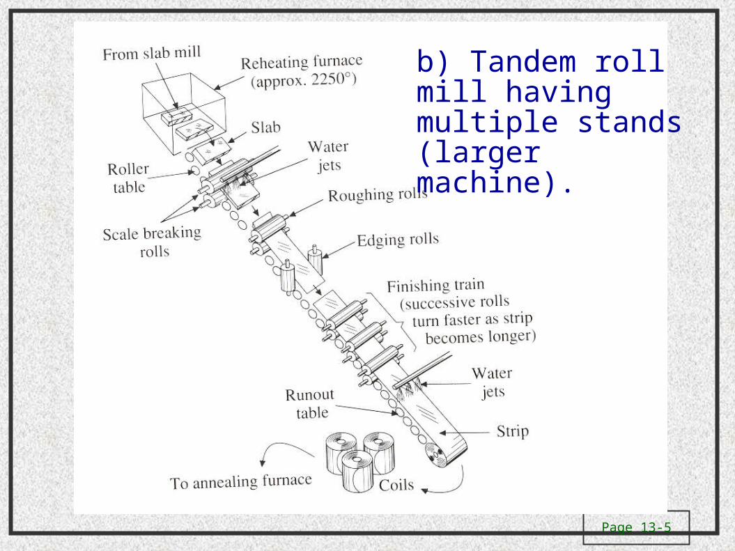
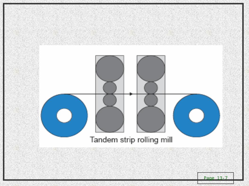
b) Tandem roll mill having multiple stands (larger machine).

Page 13-6
Page 13-7

Page 13-8
Tandem Rolling
Figure 13.12 A tandem rolling operation.

Page 13-9
Rolling Mill
Figure 13.10 A general view of a rolling mill. Source: Inland Steel.
Page 13-10
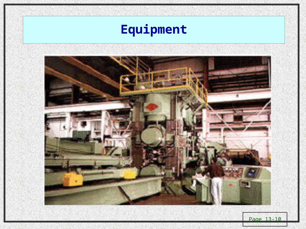
Equipment

Page 13-11
Process

Page 13-12
Page 13-13
Page 13-14
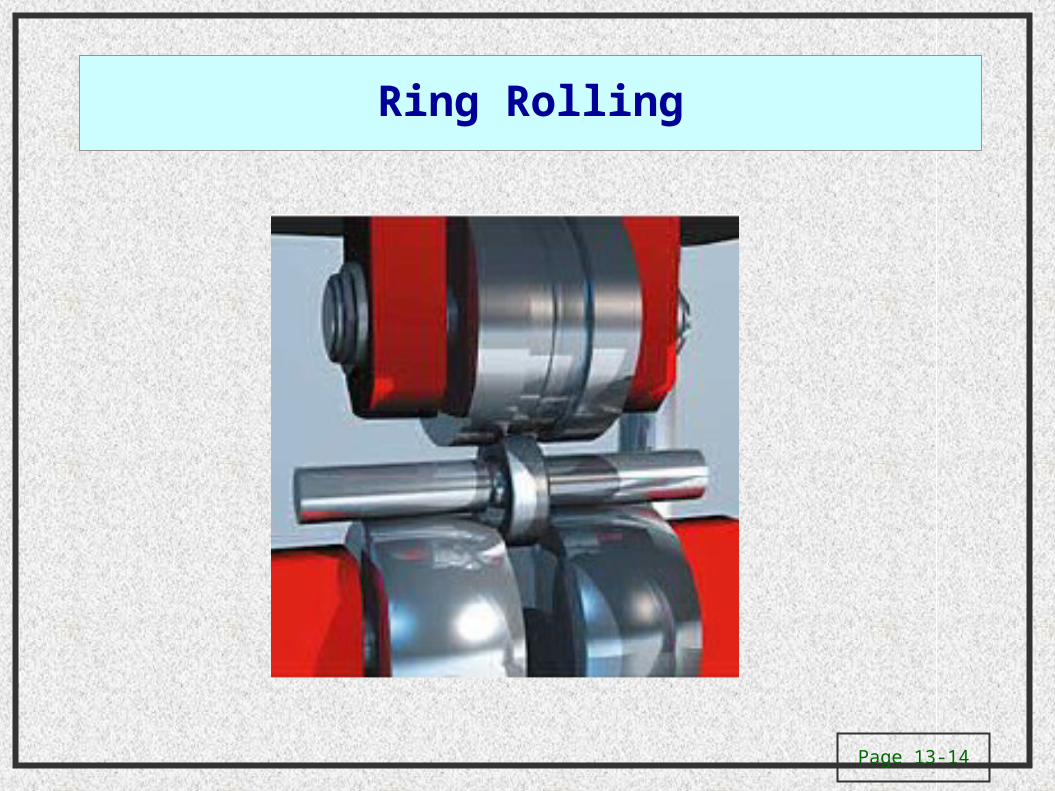
Ring Rolling

Page 13-15
Backing Roll Arrangements
Figure 13.11 Schematic illustration of various roll arrangements: (a) two-high; (b) three- high; (c) four-high; (d) cluster (Sendzimir) mill.
Page 13-16
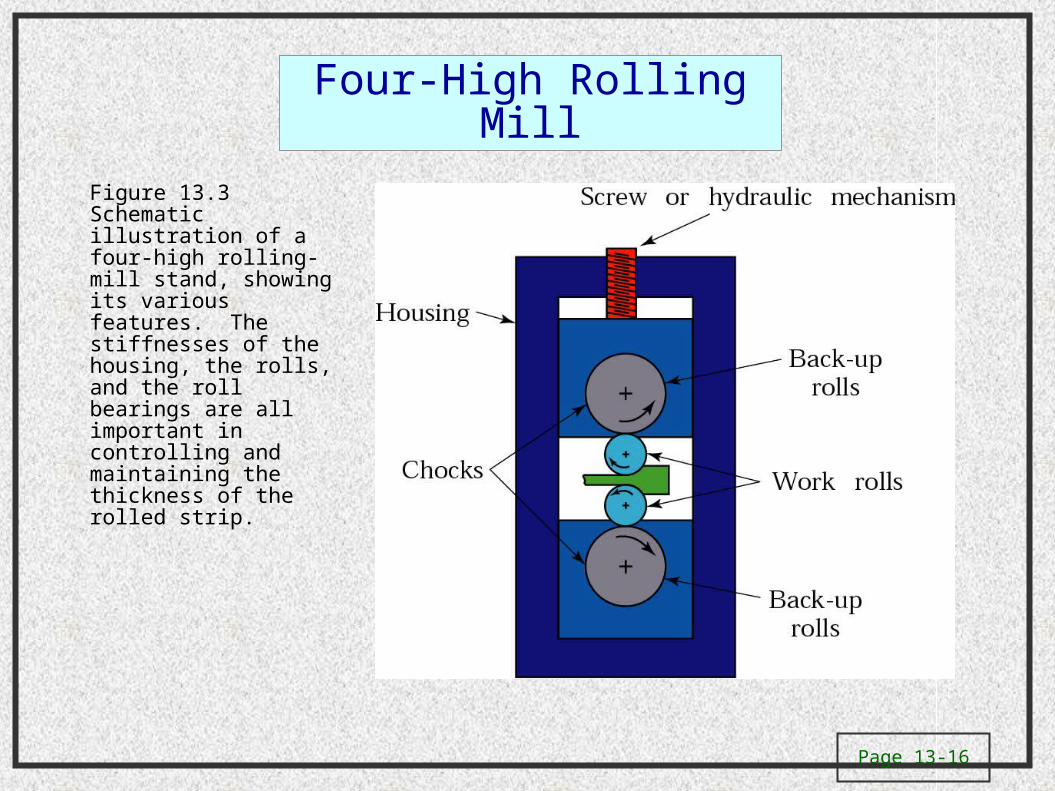
Four-High Rolling Mill
Figure 13.3 Schematic illustration of a four-high rolling-mill stand, showing its various features. The stiffnesses of the housing, the rolls, and the roll bearings are all important in controlling and maintaining the thickness of the rolled strip.

Page 13-17
Flat-Rolling
Figure 13.2 (a) Schematic illustration of the flat-rolling process. (b) Friction forces acting on strip surfaces. (c) The roll force, F, and the torque acting on the rolls. The width w of the strip usually increases during rolling, as is shown in Fig. 13.5.

Page 13-18
Effective strain and stress for strip rolling
)(0)/ln(;)/ln( 21 strainplainwwll ofof )/ln(3 of hh
)0(0 231321 where
312
12
12
12
12
32
13
2
3
2)](
3
2[)](
3
2[
2/2/)( 3312 01
3
2/123
23
3232/1213
232
221
2
3
])0()2
()2
0[(2
1])()()[(
2
1
3
23
Page 13-19
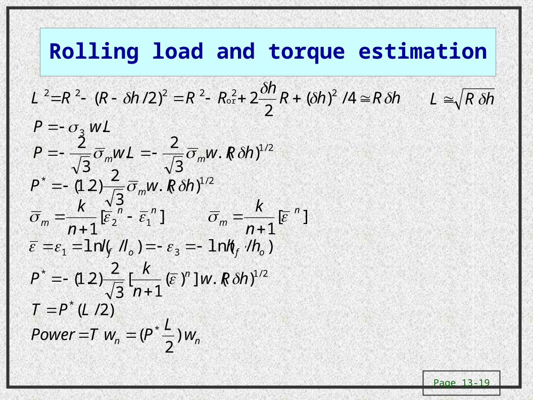
Rolling load and torque estimation
hRhRh
RRhRRL 4/)(2
2)2/( 222222 hRL or
LwP .32/1).(
3
2.
3
2hRwLwP mm
2/1* ).(3
2)2.1( hRwP m
][1 12
nnm n
k
][1
nm n
k
, )/ln()/ln( 31 ofof hhll 2/1* ).(])(
1[
3
2)2.1( hRw
n
kP n
)2/(* LPT
nn wL
PwTPower )2
( *
Page 13-20
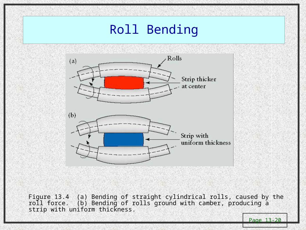
Roll Bending
Figure 13.4 (a) Bending of straight cylindrical rolls, caused by the roll force. (b) Bending of rolls ground with camber, producing a strip with uniform thickness.

Page 13-21
Spreading of a Strip
Figure 13.5 Increase in the width (spreading) of a strip in flat rolling (see also Fig. 13.2a). Similarly, spreading can be observed when dough is rolled with a rolling pin.

Page 13-22
Grain Structure During Hot Rolling
Figure 13.6 Changes in the grain structure of cast or of large-grain wrought metals during hot rolling. Hot rolling is an effective way to reduce grain size in metals, for improved strength and ductility. Cast structures of ingots or continuous casting are converted to a wrought structure by hot working.

Page 13-23
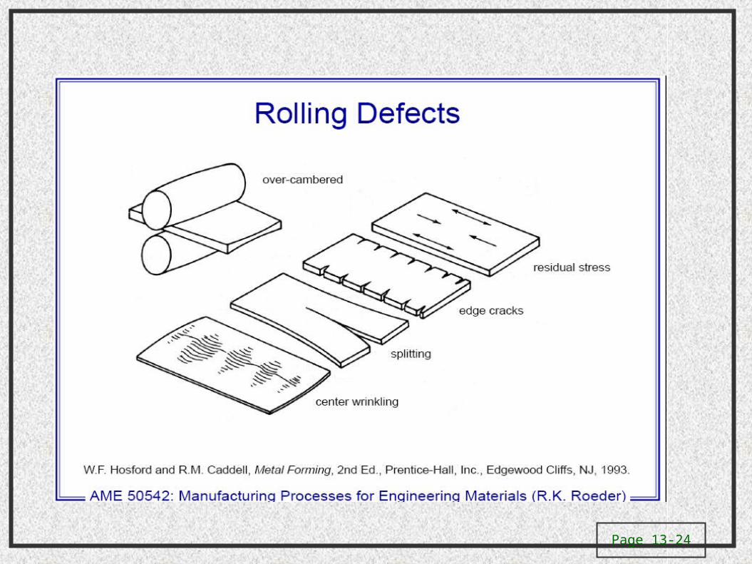
Page 13-24

Page 13-25
Residual Stresses in Rolling
Figure 13.9 (a) Residual stresses developed in rolling with small rolls or at small reductions in thickness per pass. (b) Residual stresses developed in rolling with large rolls or at high reductions per pass. Note the reversal of the residual stress patterns.

Page 13-26

Page 13-27
Ring-Rolling
Figure 13.14 (a) Schematic illustration of a ring-rolling operation. Thickness reduction results in an increase in the part diameter. (b) Examples of cross-sections that can be formed by ring rolling.

Page 13-28
Thread-Rolling Figure 13.16 (a) Features of a
machined or rolled thread. (b) Grain flow in machined and rolled threads. Unlike machining, which cuts through the grains of the metal, the rolling of threads causes improved strength, because of cold working and favorable grain flow.
Figure 13.15 Thread-rolling processes: (a) and (c) reciprocating flat dies; (b) two-roller dies. Threaded fasteners, such as bolts, are made economically by these processes, at high rates of production.

Page 13-29
Mannesmann Process
Figure 13.17 Cavity formation in a solid round bar and its utilization in the rotary tube piercing process for making seamless pipe and tubing. (The Mannesmann mill was developed in the 1880s.)
Page 13-30
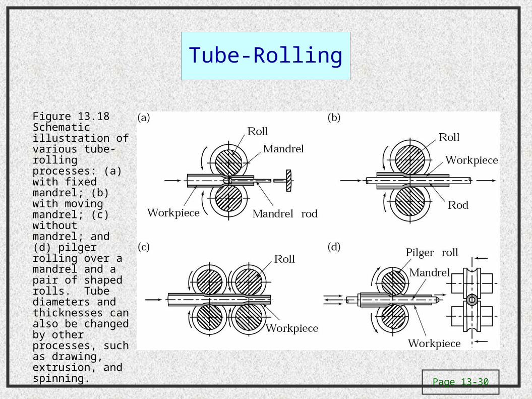
Tube-Rolling
Figure 13.18 Schematic illustration of various tube-rolling processes: (a) with fixed mandrel; (b) with moving mandrel; (c) without mandrel; and (d) pilger rolling over a mandrel and a pair of shaped rolls. Tube diameters and thicknesses can also be changed by other processes, such as drawing, extrusion, and spinning.

Page 13-31
Spray Casting (Osprey Process)
Figure 13.19 Spray casting (Osprey process), in which molten metal is sprayed over a rotating mandrel to produce seamless tubing and pipe. Source: J. Szekely, Scientific American, July 1987.