Bela Erdelyi Mike Qaissaunee Faculty Brookdale Community College, New Jersey.

Page 1Workshop 01/2011
The Accumulator/Pre-BoosterThe Accumulator/Pre-Booster
Bela Erdelyi Department of Physics, Northern Illinois University,and Physics Division, Argonne National Laboratory

Page 2Workshop 01/2011
Acknowledgements
• Joint Work with• Shashikant Manikonda (ANL)• Peter Ostroumov (ANL)• Sumana Abeyratne (NIU student)• With assistance from JLab staff (Y. Derbenev, Y. Zhang, G.
Krafft, etc.)
• Joint Work with• Shashikant Manikonda (ANL)• Peter Ostroumov (ANL)• Sumana Abeyratne (NIU student)• With assistance from JLab staff (Y. Derbenev, Y. Zhang, G.
Krafft, etc.)

Page 3Workshop 01/2011
ELIC Conceptual Layout
Three compact rings:• 3 to 11 GeV electron• Up to 12 GeV/c proton (warm)• Up to 60 GeV/c proton (cold)

Page 4Workshop 01/2011
Accumulator/Pre-Booster Concept
• Purpose:• Inject from linac• Accumulate ions• Accelerate them• Extract and send to large booster
• Concepts:• Figure-8 shape for ease of spin transport, manipulation and
preservation• Modular design, with (quasi)independent module design
optimization• FODO arcs for simplicity and ease of implementation of optics
correction schemes• No dispersion suppressors• Matched injection insertion• Triplet straights for long dispersion-less drifts and round beam• Matching/tuning modules in between

Page 5Workshop 01/2011
Constraints
• Figure-8 shaped; circumference 200-300 m• Maximum bending field: 1.5 T• Maximum quadrupole gradient: 20 T/m• Momentum compaction smaller than 1/25• Maximum beta functions less than 35 m• Maximum full beam size less than 2.5 cm, and 1 cm vertically in
dipoles• 5m m long dispersion-less sections for RF cavities, electron cooling,
collimation, extraction, and possibly decoupling• Sizable (normalized) dispersion for/at injection• Working point chosen such that tune footprint does not cross low
order resonances (tunability)

Page 6Workshop 01/2011
Injection
• Protons (and possibly light ions)• Stripping injection
• Heavy ions• Repeated multi-turn injection• Transverse (horizontal and possibly also vertical)
and longitudinal painting• Electron cooling for stacking/accumulation

Page 7Workshop 01/2011
Heavy-Ion Injection and Accumulation

Page 8Workshop 01/2011
Electron Cooling

Page 9Workshop 01/2011
Accumulated Beam
• Intensities needed to achieve design luminosity, with some safety factors included for possible losses during• Stripping• Capturing, re-capturing• Transfers
• Proton current: ~ 1A (6x10¹² total particles in the ring)
• Heavy-ion current: ~0.5 A (1x10¹¹ total particles in the ring) => ~10 linac pulses of ~ 250 μs length (subject to optimization)

Page 10Workshop 01/2011
Acceleration
• h=1• RF swing necessary is [0.4,2] MHz
• 4 kV per cavity• 50kV/turn => 12-13 cavities• Synchronous phase ~ -30˚• 65000 turns for 200MeV -> 3 GeV• ~100 ms acceleration time
• Allows acceleration with h=2 with the same cavities, if needed

Page 11Workshop 01/2011
LEIR-Type Cavities
• Finemet cavities• 0.5 m long• 4kV/cavity• [0.35,5] MHz
frequency swing• Practically no
maintenance needed

Page 12Workshop 01/2011
Extraction and stripping
• Conventional single-turn fast extraction
• To minimize heavy-ion loss, strip once in linac and once after the pre-booster to maximize fully stripped fraction• Advantages:
• Less beam-loss to reach fully stripped state• Less severe space charge in pre-booster
• Drawback: lose some energy gain

Page 13Workshop 01/2011
Layout
ARC 1
Injection Insertion section
ARC 2
Non dispersive section 1
ARC 3
Non dispersive section 2
RF Cavities
Electron Cooling
Solenoids for Electron Cooling and Decoupling
ExtractionCollimation
Beam from
LINAC
To Large Booster

Page 14Workshop 01/2011
Circumference
Total length of the long drifts in the straights = 20m

Page 15Workshop 01/2011
Linear Optics
Inje
ctio
n
Arc
1
Str
aig
ht
1 Arc
3
Str
aig
ht
2 Arc
2

Page 16Workshop 01/2011
Optical modules
ARC1&2 FODOARC3 FODO
STRAIGHT TRIPLET INJECTION INSERT

Page 17Workshop 01/2011
Matching/Tuning modules

Page 18Workshop 01/2011
Tunability

Page 19Workshop 01/2011
Main Parameters Units Value
1 Circumference m 3022 Angle at crossing deg 443 Number of dispersive FODO cells (Type I) 64 Number of dispersive FODO cells (Type II) 85 Number of triplet cells 186 Number of matching cells (2 types) 47 Minimum drift length between magnets cm 50 8 Drift length in the injection insertion m 5.09 Drift lengths between triplets (for RF, extraction, collimation and electron
cooling)m 5.3
10 Beta maximum in X m 3311 Beta maximum in Y m 3612 Maximum beam size cm 2.312 Maximum vertical beam size in the dipole magnets cm 0.6
13 Maximum dispersion (x|delta_KE) m 3.314 Normalized dispersion value at injection insert m½ 2.115 Tune in X 7.9216 Tune in Y 7.2417 Gamma of particle 4.2218 Gamma at transition energy 5.619 Momentum compaction 3.2E-2
Page 20Workshop 01/2011 20
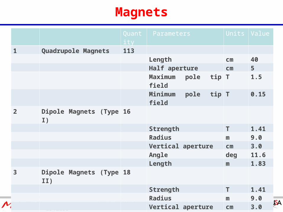
Magnets
Quantity
Parameters Units Value
1 Quadrupole Magnets 113Length cm 40
Half aperture cm 5Maximum pole tip field T 1.5
Minimum pole tip field T 0.152 Dipole Magnets (Type I) 16
Strength T 1.41Radius m 9.0
Vertical aperture cm 3.0Angle deg 11.6
Length m 1.833 Dipole Magnets (Type II) 18
Strength T 1.41Radius m 9.0
Vertical aperture cm 3.0
Angle deg 14.0Length m 2.19

Page 21Workshop 01/2011
Beam Parameters at the End of the Pre-Booster Cycle
Proton Lead
Beam energy GeV 3 1.18
Particles number 1012 6 0.1
Beam Current A 1 0.5
Polarization % >90% (est.) N/A
Energy spread 10-4 ? ?
Bunch length m 63 63
Horizontal acceptance, normalized µm rad 55 28
Vertical acceptance, normalized µm rad 37 12
Laslett tune shift (after injection) 0.071 0.015

Page 22Workshop 01/2011
Pre-Booster Cycle Time
• Assuming 1x10¹¹ lead ions need to be accumulated• One 250 μs long linac pulse (subject to optimization) delivers ~
0.5 mA• Assume ~50% injection efficiency (CERN experience)• => 9 linac pulses• Cooling time estimated to be ~130ms• => Total time =
• 9x 250 μs (injection) +• 9x130 ms (cooling) +• 2x100 ms (acceleration and de-ramping)• ≈ 1.4 s
• Assuming factor of 4 ratio between circumferences between pre-booster and large booster, and acceleration with -30˚ => 16 cycling times needed to fill the large booster => 22s (~3s for p)
• Large booster starts with coasting beam

Page 23Workshop 01/2011
Summary and Work in Progress
• Design of the accumulator/pre-booster is well underway• Satisfies the constraints while providing superior performance
• Fine tuning first order optics• Space charge simulations; limits on current and emittance• Spin tracking, polarization preservation studies• Dynamic aperture estimation
• Design of the accumulator/pre-booster is well underway• Satisfies the constraints while providing superior performance
• Fine tuning first order optics• Space charge simulations; limits on current and emittance• Spin tracking, polarization preservation studies• Dynamic aperture estimation

Page 24Workshop 01/2011
BACKUP SLIDES

Page 25Workshop 01/2011
Cooling times
• Assuming:• 3 m long cooling section• 300 mA electron current• 2.5 cm beam radius• ± 5 mrad beam divergence• ±0.004 momentum dispersion• Cooling for 3 time constants
Transverse cooling time: ~ 130 ms Longitudinal cooling time: ~ 67 ms
Cooling electron energies:• @ injection: { 0.55394 MeV, γ=2.0840 }• @ extraction: { 1.15511 MeV, γ=3.2605 }

Page 26Workshop 01/2011
Lead Charge Distributions
• @ injection• Q (0) Q (1) Q (2) Q (3) Q (4)• 0 4% 70% 22% 3%
• @ extraction• Q (0) Q (1)• 80% 20%

Page 27Workshop 01/2011
Shorter Version (C=250m)

Page 28Workshop 01/2011
Linear Optics

Page 29Workshop 01/2011
Optical Modules

Page 30Workshop 01/2011
Units Value1 Total length m 2542 Angle at crossing deg 623 Number of dispersive FODO cells (Type I) 6
4 Number of dispersive FODO cells (Type II) 9
5 Number of triplet cells 106 Number of matching cells 47 Minimum drift length between magnets cm 50
8 Drift lengths in the insertion region m 5.0
9 Drift lengths between triplets (for RF, collimation and electron cooling) m 5.0
10 Beta maximum in X m 1911 Beta maximum in Y m 3412 Maximum beam size cm 2.0
12 Maximum beam size in the dipole magnets cm 0.6
13 Maximum Dispersion (x|delta_KE) 2.5
14 Normalized dispersion value at injection (x|δ_KE)/√β 1.41
15 Tune in X 8.3316 Tune in Y 7.4317 Gamma of particle 4.2218 Gamma at Transition Energy 5.62
19 Momentum compaction factor 0.031
Main Parameters

Page 31Workshop 01/2011
Quantity Parameters Units Value1 Quadrupole Magnet 95 Length cm 40 Half aperture cm 5 Maximum pole tip
fieldT 1.5
Minimum pole tip field
T 0.16
2 Dipole Magnet (Type I) 6 Strength T 1.41 Radius m 9 Vertical aperture cm 3
Angle deg 14 Length m 2.193 Dipole Magnet (Type II) 12 Strength T 1.41 Radius m 9 Vertical aperture cm 3
Angle deg 13.17 Length m 2.064 Dipole Magnet (Type III) 18 Strength T 1.41 Radius m 9 Vertical aperture cm 3
Angle deg 13.44 Length m 2.11
Magnets

Page 32Workshop 01/2011
Laslett Tune Shift (protons)
• Beta=0.57
• Gamma=1.21
• Nt(total)=5.36E+12
• rc = 1.53E-18m
• EN(normalized)=Beta*Gamma*9E-6 m.rad
• BF=1 (Peak to average current radio)
• laslett_tune_shift=-(Nt*rc*Bf)/(4*pi*EN*beta*gamma^2)
• laslett_tune_shift=-0.071.

Page 33Workshop 01/2011
Laslett Tune Shift (Lead)
• Beta=0.37
• Gamma=1.08
• Nt(total)=4.33E+10
• rc = 1.53E-18m
• EN(normalized)=Beta*Gamma*17.5E-6 m.rad
• BF=1 (Peak to average current radio)
• laslett_tune_shift=-(Nt*rc*Bf*Q^2)/(4*pi*EN*M*beta*gamma^2)*
• laslett_tune_shift=-0.015.


![Lermontov Bela.doc · Web viewMikhail Lermontov [Bela] Bela Bela [I] Ай Я [was] воз был [traveling] traveling путешествие [along] элонг вперед [the]](https://static.fdocuments.us/doc/165x107/6000c96ccd2c3329594c851b/lermontov-beladoc-web-view-mikhail-lermontov-bela-bela-bela-i-was.jpg)


![Solutions of Nonlinear Integral Equations · examined in considerable detail for the linear case by Erdelyi [3], [4], and [5], and in some detail for the nonlinear case by Erdelyi](https://static.fdocuments.us/doc/165x107/5ec043cedf8e6c207758062d/solutions-of-nonlinear-integral-equations-examined-in-considerable-detail-for-the.jpg)