![USOO5685946A United States Patent Patent Number: …United States Patent 1191 Fathauer et al. USOO5685946A 1111 Patent Number: 5,685,946 [4s] Date of Patent: Nov. 11, 1997 [54] METHOD](https://static.fdocuments.us/doc/165x107/61224d5aed3283123d24645c/usoo5685946a-united-states-patent-patent-number-united-states-patent-1191-fathauer.jpg)
Page 1 United States Patent 1191 1111 4,034,756 Higuchi et a1. [45 ...
12
United States Patent 1191 1111 4,034,756 Higuchi et a1. [45] July 12, 1977 [54] OSMOTICALLY DRIVEN FLUID DISPENSER 3,760,806 9/1973 ldeeper ............................ .. 128/260 3,760,984 9 1973 Th .................... .. 128 260 X [75] Inventors: Takeru I-liguchi, Lawrence, Kans; I eeuwes / Harold M. Leeper, Mountain View, OTHER PUBLICATIONS Cahf' > I & EC Process Design and Development, vol. 5, No. 4, [73] Assignee: Alza Corporation, Palo Alto, Calif. Oct- 1966, PP- 422-429 1211 Appl- No.: 666,365 Primary Examiner-Aldrich F. Medbery [22] Filed; Mar. 12, 1976 Attorney, Agent, or Firm—Thomas E. Ciotti; Edward L. Mandell; Paul L. Sabatine R l t .S. 11 ' 63 C ' e f‘ U A: “302318626 S [57] ABSTRACT [ 1 lgglynélsttfwg'nglrgstsg3Cums‘ is a’ ’ ept' 25’ An osmotically driven ?uid dispenser for use in _an continuation-in-part of Ser. No. 106,161, Jan. 13, aquFous emflronment compnsmg: a shape retammg 1971, abandoned, canister having controlled permeability to water; an osmoticall effective solute con?ned in the canister Int. CL: ................ .. which’ in syolution, exhibits an osmotic pressure gradi_ 52 U S Cl 128 26 ent against the water in the environment; an outlet in [ 1 ' ' ' """""""""""""""" " I 2 ’_ I ' the canister wall; and a ?exible bag of relatively imper , 128] 13’ 128/ 271 vious material that holds the ?uid to be dispensed and Fleld of Search ................. .. is housed in the canister with open end in Sealed [5 6] References Cited Contact with the canister such that the canister outlet communicates with the bag interior and the bag inter U'S‘ PATENT DOCUMENTS ior is closed to the ‘solute and aqueous solution thereof 2,962,023 11/1960 Chappaz et a1. ................. .. 128/260 with the remainder of the bag spaced from and gener 3,556,992 1/1971 Massucco . . . . . . . . . . . . . . . .. 210/23 ally unsupported by the‘ canister walL 3,561,644 2/1971 Works et a1. . . . . . . . . . . . . . . ,- 128/260 3,604,417 9/1971 Stolzenberg et al. .. 128/213 3,760,805 9/1973 Higuchi ........................... .. 128/260 9 Claims, 8 Drawing Figures 24 2O / v . . ’ % ' 22 Z -. _ _|§ . . \ . I ' ' l I I‘ N 7\. -_ . _\ A\- n I‘ _-\ _ —_\ 1o / Q5; ~ ~ ' i: \r__ I: \ Z\:; Ii; _ _ ._ __.\ Z=- _ - a J2 . l4 \ ~ 12 \ _ __ _____ ~ / Z\_ —- -_ 36C\Z ' \ — — —— ‘7- 3o \ _\ __-¢ /z_ 36* _ -2 34/ __ __ __ 7 \ I IQ ' 7, — — ——= —, \ —— __ _ /)//////// % / L 38
-
Upload
nguyendieu -
Category
Documents
-
view
219 -
download
1
Transcript of Page 1 United States Patent 1191 1111 4,034,756 Higuchi et a1. [45 ...

United States Patent 1191 1111 4,034,756 Higuchi et a1. [45] July 12, 1977
[54] OSMOTICALLY DRIVEN FLUID DISPENSER 3,760,806 9/1973 ldeeper ............................ .. 128/260 3,760,984 9 1973 Th .................... .. 128 260 X [75] Inventors: Takeru I-liguchi, Lawrence, Kans; I eeuwes /
Harold M. Leeper, Mountain View, OTHER PUBLICATIONS Cahf' > I & EC Process Design and Development, vol. 5, No. 4,
[73] Assignee: Alza Corporation, Palo Alto, Calif. Oct- 1966, PP- 422-429
1211 Appl- No.: 666,365 Primary Examiner-Aldrich F. Medbery [22] Filed; Mar. 12, 1976 Attorney, Agent, or Firm—Thomas E. Ciotti; Edward L.
Mandell; Paul L. Sabatine R l t .S. 11 '
63 C ' e f‘ U A: “302318626 S [57] ABSTRACT [ 1 lgglynélsttfwg'nglrgstsg3Cums‘ is a’ ’ ept' 25’ An osmotically driven ?uid dispenser for use in _an
continuation-in-part of Ser. No. 106,161, Jan. 13, aquFous emflronment compnsmg: a shape retammg 1971, abandoned, canister having controlled permeability to water; an
osmoticall effective solute con?ned in the canister Int. CL: ................ .. which’ in syolution, exhibits an osmotic pressure gradi_
52 U S Cl 128 26 ent against the water in the environment; an outlet in [ 1 ' ' ' """""""""""""""" " I 2 ’_ I ' the canister wall; and a ?exible bag of relatively imper
, 128] 13’ 128/ 271 vious material that holds the ?uid to be dispensed and Fleld of Search ................. .. is housed in the canister with open end in Sealed
[5 6] References Cited Contact with the canister such that the canister outlet communicates with the bag interior and the bag inter
U'S‘ PATENT DOCUMENTS ior is closed to the ‘solute and aqueous solution thereof 2,962,023 11/1960 Chappaz et a1. ................. .. 128/260 with the remainder of the bag spaced from and gener 3,556,992 1/1971 Massucco . . . . . . . . . . . . . . . .. 210/23 ally unsupported by the‘ canister walL
3,561,644 2/1971 Works et a1. . . . . . . . . . . . . . . ,- 128/260
3,604,417 9/1971 Stolzenberg et al. .. 128/213 3,760,805 9/1973 Higuchi ........................... .. 128/260 9 Claims, 8 Drawing Figures
24 2O
/ v . .
’ % ' 22
Z -. _ _|§ . . \ . I ' ' l I I‘ N
7\. -_ . _\ A\- n I‘ _-\
_ —_\
1o / Q5; ~ ~ ' i: \r__ I: \
Z\:; Ii; _ _ ._ __.\
Z=- _ - a J2 . l4 \ ~ 12 \ _ __ _____ ~ /
Z\_ —- -_ 36C\Z ' \ — — —— ‘7- 3o
\ _\ __-¢ /z_ 36* _ -2
34/ __ __ __ 7
\ I IQ ' 7, — — ——= —,
\ —— __ _
/)//////// % / L
38


US. Patent July12, 1977 Sheet 2 of4 4,034,756
20
2/
B
6 . O
I 4
I I \ a
,
'
a , l . . ._ ______
__ __
\ \ \
yv§\\\\\\\v\\ \\\\ \ A; _ _ ~
4M
(36

U.S. Patent July 12, 1977 Sheet 3 of4 4,034,756
FIG. 6
U.S. Patent July12, 1977 Sheet4 of4 4,034,756
44
“ "II/I ' '
42

4,034,756 I
OSMOTICALLY DRIVEN FLUID DISPENSER
CROSS REFERENCE TO RELATED APPLICATIONS
This application is a continuation-in-part of applica tion Ser. No. 29l,686, ?led Sept. 25, I972, now Pat. No. 3,995,631, which in turn is a continuation-in-part of application Ser. No. I()6,l6l, ?led Jan. I3, I97I, and now abandoned.
BACKGROUND OF THE INVENTION
Field of the Invention
This invention relates to an osmotic dispenser, and, more especially, to an osmotic dispenser, simple in construction, capable of dispensing a ?uid, such as an active agent at an osmotically controlled ‘rate over a continuous and prolonged period of time.
SUMMARY OF THE INVENTION
The invention is an osmotically driven ?uid dispenser for use in an aqueous environment consisting essen! tially of:
‘a. a single shape retaining closed canister that defines the exterior of the dispenser which exterior is exposed completely to the aqueous environment, at least a por tion of the wall of the canister being made of a material of controlled permeability to water;
b. an osmotically effective solute con?ned within the canister which, in aqueous solution, exhibits an osmotic pressure gradient across said portion of the canister wall against the water of said environment, said canis ter being substantially impermeable to the solute;
c. an outlet in the canister wall; and d. a ?exible bag adapted to hold the ?uid to be dis
pensed and. housed within the canister with its open end in sealed contact with the canister wall such that the outlet communicates with its interior and its interior is closed to the solute and aqeuous solution thereof with the remainder of the bag being spaced from the canis ter wall and generally unsupported thereby, the exte rior of said remainder being exposed to the solute and aqeuous solution thereof, whereby water is imbibed into the canister from the environment through said portion of the canister wall by the solute and the im bibed water exerts hydraulic pressure uniformly on the exterior of the ?exible bag exposed thereto, causing the bag to collapse inwardly thus squeezing the ?uid out of the bag via the outlet.
Description of the Prior Art
The prior art to the invention is described in detail in the ?le of patent application Ser. No. 291,686, ?led Sept. 25, I972, now US. Pat. No. 3,995,631. '
BRIEF DESCRIPTION OF THE DRAWINGS
In the drawings: 7 FIG. I is a cross-sectional view of an osmotic dis
penser of this invention; FIG. la is a top view of the osmotic dispenser of FIG.
I; , .
FIG'. 2 is a cross-sectional view of another osmotic dispenser‘ of this invention; FIG. 3 is a cross-sectional view of yet another os
motic dispenser of this invention; '
20
25
30
35
45
55
65
2 FIG. 4 is a cross-sectional view of still another os
motic dispenser of this invention; and FIG. 5 is an exploded view of the dispenser of FIG. 4; FIG. 6 is a schematic view of the construction and
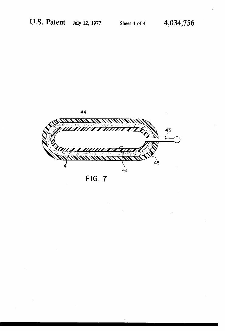
fabrication of still another osmotic dispenser of this invention, designated as the “mini-pump" embodi ment; and FIG. 7 is a cross-sectional view ‘of another mini-pump
osmotic. dispenser of this invention.
DETAILED DESCRIPTION OF THE INVENTION
The expression “active agent" as used herein denotes any drug (as defined, infra); composition in any way affecting any biological entity; substance having a nu trient or stimulating action, or growth inhibiting, de stroying or any regulating action on plant growth, con trolled or otherwise; substance to be assimilated by any organism, e.g., human ,being, animal, or lower order organism, for its nourishment or for regulating its growth; substance exhibiting any of the above activities to be directly applied to the habitat, surroundings or environment of any of the above organisms; and sub stance having any other effect on any other environ ment, especially any aqueous environment. Therefore, suitable active agents for use with the
dispenser of this invention include, without limitation, those which are generally capable of:
I. Preventing, alleviating, treating or curing abnor mal of pathological conditions of the living body by such means as destroying a parasitic organism or limit ing the effect of the disease or abnormality by chemi cally altering the physiology of the host or parasite;
2. Maintaining, increasing, decreasing, limiting or destroying a physiologic body or plant function, e.g., vitamin compositions, sex sterilants, fertility inhibitors, fertility promoters, growth promoters, and the like;
3. Diagnosing a physiological condition or state; 4. Controlling or protecting an environment or living
body by attracting, disabling, inibiting, killing, modify ing, repelling or retarding an animal or microorganism, such as food and non-food baits, attractants and lures, biocides, pesticides, algicides, parasiticides, rodenti cides, insecticides, fungicides, and the like;
5. Preserving, disinfecting or sterilizing; and 6. Controlling or affecting generically an enviroment,
as by introducing a catalyst or metering a reactant into a reacting chemical system, or by effecting any chemical process therein, such as a fermentation, including propagation and/or attenuation of a mi croorganism. ‘
The term “aqueous environment,” as used herein above and herein, means an environment that sur rounds the external surface of the canister of the dis penser and that contains suf?cient water for absorption into the dispenser to develop the needed osmotic pres sure on which its motive force depends. This term does not include sources of water that are af?xed to the exterior of the dispenser.
In one embodiment in accordance with this inven tion, as illustrated in FIG. 1, an osmotic dispenser I0 is comprised of a rigid canister 12, at least a portion of the wall membrane de?ning the same exhibiting con trolled permeability to water, as hereinafter more fully explained. Housed within the canister I2 is a ?exible bag 14 of relatively impervious material. The said ?exi ble bag 14 contains the ?uid to be dispensed I6, advan tageously a drug formulation in a liquid, suspension, gel, paste or other ?uid state. The volume of the canis~

4,034,756 3
ter vl2, other than that occupied by the ?exible bag 14 and ?uid 16, is occupied by a solution 18 of an osmoti cally effective solute which exhibits an osmotic pres sure gradient against the water in the environment. The open end of canister 12 is tightly sealed or closed off with rigid, impervious dispensing head, plug or delivery cap 20, with the open end of the ?exible bag 14 being concentrically secured therebetween (see also FIG. la). In this manner a tight barrier is maintained be tween and among the ?uid 16 in the ?exible bag 14, the solution 18 in the canister 12, and the external environ ment of the dispenser 10. Without this tight barrier, undesirable contamination could take place. The dis pensing head 20 is preferably snapped or press-?t in place with the ?exible bag 14 either being already'cir cumferentially tightly secured thereto or to the upper, inner periphery of the canister 12. Alternatively, these three elements may conveniently be heat sealed to gether, and, as an aid in maintaining the tight barrier, a chamfered polycarbonate retaining ring 22 may option ally be pres's-fit about the top of the dispenser 10. An outlet 24 extends through head 20 and provides com munication from the interior of the flexible bag 14 to the exterior of the dispenser 10, said outlet advanta geously being approximately 0.0625 inch in diameter. As seen in FIG. 1, bag 14, except for the end that is secured between the wall of canister 12 and head 20, is spaced from the wall of ‘the canister and is generally unsupported thereby. In other words the bag 14 hangs freely in canister 12 without any lateral or’ bottom sup port. The exterior surface of bag 14 except for said end, is exposed to solution 18. When the ?uid is a drug or other agent for treating a
living organism, dispenser I0 is either physically in sert'ed or surgically implanted in the body of the organ ism, typically a mammal, or is administered via the gastrointestinal tract. Once in place, water will be ab sorbed therein from either body tissues or body ?uids through the'area of the canister 12 which exhibits the controlled permeability to water and in an e?'ort to reach osmotic equilibrium, Le, a transition from hyper tonicity to isotonicity. As the ?uid ?ows by osmosis into the canister 12 the volume of the solution 18 is thus increased and, corresponding pressure is exerted uniformly, multidirectly and inwardly against the exte rior surface of bag 14 that is exposed to solution 18. Such pressure serves to squeeze the drug formulation 16 out of the bag 14 through the outlet 24 at an osmoti cally controlled and constant rate into the external environment. There is accordingly provided the grad ual and controlled constant release of drug or similar agent directly to the body or affected organ thereof over a prolonged period of time. Also, because of the nature of the pressure exerted on bag 14, bag 14 col lapses uniformly inwardly thus insuring substantially complete dispensing of formulation 16. The design of the canister 12 is such that a given area
of the wall members de?ning the same displays perme ability to water at an osmotically controlled rate. Said canister, therefore, is either of unit or composite con struction and is advantageously comprised of a semi permeable membrane, with same either defining an integral wall member of the canister, or a lining, or in some manner is laminated thereto or otherwise dis posed in the desired functional relationship.
In FIG. 2, forexample, there is illustrated an osmotic active agent dispenser 10 wherein the canister 12 is comprised of rigid, impervious, cylindrical plastic side
5
20
25
30
35
40
45
55
65
4 wall member 30, and __bottom wall member 32 integral therewith. Bored intothe said bottom wall member 32 are a plurality of ori?ces or ducts 34, each preferably about l/ l 6 inch in diameter. It will thus be appreciated that, being highly porous, only the bottom wall member 32 of the canister 12 is capable of admitting water into the device, the said cylindrical side wall member 30 remaining ?uid impenetrable. It is not intended that the highly porous bottom wall member‘32 in any way act as a barrier to or restrict the transport of ?uid. Securedly affixed and supported atop the said perforated bottom wall member 32 is a ?at disc 36 of membrane which exhibits controlled permeability to external ?uid, e_.g., water. The membrane 36 may, for example, either be ashesively secured. in place or may be lined or lami nated to, or cast from solution atop the said bottom wall member 32. The aforementioned casting atop the porous wall 32 is- advantageouslyyperfected by deposit ing the ?lm or disc from a solution of membrane form'~ ing material in a solvent, e.g., a 20% solution of cellu lose acetate in an acetone-ethanol-ethyl lactate mixed solvent, 65% —- 20% -— 15%, respectively. In casting the film, careshould be taken that the pores of the wall member 32 do not become clogged. And it is of course intended that the [seal ‘between the membrane 36 and the porous wall 32 bewatertight such that ?uid is per mitted access to the interior of the'device only by dif fusing by osmosis through the said membrane 36. As too will be appreciated, it is also possible thatthe mem~ brane 36 be affixed beneath the said bottom wall mem ber 32. The design of the FIG. 2 is moreover unique in that it requires a membrane of but limited surface area relative to the overall dimensions of the canister. This because of the ready availability of the highly water‘ permeable cellulose acetate‘membranes designedfor use in reverse osmosis processes for water desalination. ' These membranes, typically and preferably anisotropic membranes, are highly permeable to water (allow rela tively rapid rates of water transmission) but are rela tively impermeable to salt, thus permitting their use in relatively small exposure area devices. ‘And water will migrate into the dispenser only at the point of exposure of the membrane 36 with the outside environment via the ducts 34. . ’
Optionally, in an alternative embodiment of the in vention, a separatorof porous paper, fabric or the like can conveniently be disposed between the bottom ‘wall member 32 and the membrane 36. This prevents the membrane from being punctured or drawn into too tight a contact with the canister, thereby assuring that the ‘entire membrane is exposed to the ?uid environ- I ment. The immediately above option also applies to a device such as illustrated in FIG. 3. Furthermore, use ‘of the porous separator aids in the aforesaid embodiment of casting the membrane from solution, same providing a ready-made molding or casting surface with no dan ger of ori?ces 34 clogging. ' In FIG. 3.there is depicted an osmotic ?uid dispenser 10 which allows for higher available exposure area of membrane 36 and, accordingly, which design takes advantage of the availability of a far greater number of membranes than the semi-permeable, anisotropic cel lulose acetate membranes of the type used in reverse ‘ osmosis water desalination. In this embodiment it is the rigid, impervious, cylindrical plastic side wall member 30 which is‘ provided with the plurality of ori?ces or ducts 34, again, each preferably being about l/l6 inch in diameter, and it is this perforated wall 30 which is

4,034,756 5
tightly ?tted, as in FIG. 2, with the membrane 36, in this instance a membrane of cylindrical con?guration. Many and varied designs intermediate in construction between the designs of the FIG. 2 and FIG. 3 dispens-, ers, insofar as available exposure area of membrane is concerned, are of course within the scope of the inven tion.
In some instances, the dispenser is of insuf?cient speci?c gravity to maintain placement at the desired location. For example, for use in the rumen of polygas tric animals, the weight should be suf?cient to provide a speci?c gravity of at'least l.5. In those instances of insufficient speci?c gravity, therefore, a weight of bal last can be placed in the dispenser, such as the steel ball 38 of FIG. 3. Other suitable weights comprise iron plugs, iron ore tablets, brass plugs, ceramic plugs, or the like. When the fluid 16 is other than a drug or similar
agent, or is intended for use other than in a living or ganism, the device is introduced into the desired aque ous environment to produce the desired effect exactly as would be any of the known means for accomplishing a like result. '
If desired, long ?exible tubing of polyethylene or the like can be extended from the dispensing head of the dispenser of either of FIGS. 1, 2 or 3. In such manner the dispenser can be deposited at a site remote from the desired point of application and still release its active agent contents through the dispensing head and then through the tube directly to said point. This permits placement of the dispenser in a ?uid environment and release of the active agent into another environment which need not be ?uid. The dispensing head can also be provided with a check valve, for example, a one way bell valve, to prevent back ?ow of active agent or other materials from the external environment into the dis penser. Moreover, a dispenser of either FIG. 1, FIG. 2 or
FIG. 3 type is admirably suited for the continuous ad ministration of the antibiotic oxytetracycline to beef cattle from the rumen. This because such devices can easily be fabricated of a size, weight and shape as to be retained in the rumen of polygastric animals to release drug or similar agent thereto at a carefully controlled rate. Other variations on the basic theme‘ would be readily apparent to the skilled artisan. Although partic ular cn?gurations may be designed for speci?c body uses, e.g., for use in the stomach or rumen, uterus, vagina, bladder, etc., each of these con?gurations is applicable to use in other environments. For another example, an ocular insert can similarly easily be fabri cated of a‘ size and shape adapted for insertion in the eye, e.g., the cul-de-sac of the conjunctiva between the sclera of the eyeball and the lower lid, to be held in place against the eyeball by the pressure of the lid. Compare in this respect US. Pat. Nos. 3,416,530, and 3,618,604. The membrane 36 of FIGS. 2 and 3 and that portion
of the wall members de?ning the canister 12 of FIG. 1 which exhibits controlled permeability to external ?u ids can be formed from a wide variety of materials permeable or semi-permeable to solvent but not to solute, i.e., those suitable for the construction of an osmotic cell. For best results, the membrane should be substantially impermeable to passage of the osmotically effective solute so as to prevent loss thereof. Typical membranes are isotropic membranes such as unplasti cized cellulose acetate, plasticized cellulose acetate,
20
25
30
35
40
45
50
55
60
65
6 reinforced cellulose acetate, cellulose di- and triace tate, ethyl cellulose?‘ anisotropicreverse osmosis mem branes which‘ typi‘cally'are made of cellulose acetate; silicone rubbers, polyurethanes, natural rubber, and hydrolyzed ethylene/vinyl acetate copolymers. Iso tropic membran‘es have less water permeability than do the anisotropic membranes. Also, with both types of membranes, increasing the acetate content of the cellu lose acetate polymer decreases the water permeability. Since, as previously described, the=surface area of the membrane is relatively limited in a dispenser of FIG. 2 type, it will be preferred to use semi-permeable mem branes allowing relatively rapid water transmission in this general category of dispensers. Thus,v in such em bodiments the anisotropic membranes ‘are the pre ferred. A cellulose acetate membrane suitable for this limited surface area application is Eastman Chemical Products Type R0 97, which is rated to be permeable to 1.5 to 2 cc/cmzlday at atmospheric pressure, against a saturated solution of K2804 at 39° C. A speci?c exam ple of the design of FIG. 2 constructed with polymeth ylmethacrylate dispensing head and having an inner diameter of 1.9 cm is capable of delivering 4 to 6 cc of active agent, advantageously a‘ drug, per day. In one speci?c embodiment of a dispenser of FIG. 3 type, the membrane used was an isotropic cellulose acetate membrane, with no plasticizer, having an acetate sub stitution of 2.4, being 3 mils thick, and passing water at the rate of 70 mg/cm2 per day against a saturated mag nesium sulfate solution of 39° C. The membranes too are insoluble, and chemically compatible with the salt solution and any excess solute therein. For drug depot applications asheretofore described, the membranes are also biologically inert, non-irritating to body tissues and nonallergenic. For devices designed to deliver ac tive agents relatively rapidly for a limited period, mem branes of controlled high fluidpermeability are indi cated; membranes of lower ?uid permeability are used to provide slower and more prolonged delivery. The impermeable bag 14 of the osmotic dispensers of
the ?gures of the drawing containing the active agent composition should besubstantially impermeable both the ?uid, and the other elements of the environment on which a device of such type is intended to be placed, the osmotically effective solute, and components of the active agent composition. Typical materials for use as the impermeable bag include polyethylene, polyethy lene terephthalate (Mylar), plasticized polyvinyl chlor ide, metal-foil polyethylene laminates, neoprene rub ber, natural gum rubber, and Plio?lm (rubber hydro chloride). These materials are additionally ?exible, insoluble and chemically compatible with the active agent therein, and, in the instance of providing a drug or like depot within the body of a living organism, are biologically inert, non-irritating to body tissues and non-allergenic. '
The impermeable vplastic canister 12 of FIGS. 2 and 3 and impermeable portions of the canister 12 of FIG. 1 too are insoluble and can be formed of polystyrene, polyethylene, polypropylene, polyvinyl chloride, rein forced epoxy resin, polymethylmethacrylate, etc., sheet metal (e.g., aluminum, copper, steel, ’etc.), galvanized pipe, or styrene/acrylonitrile copolymer. It is of 'course intended that such casing or shell act as a barrier to the transport of ?uid, except at‘the areas of perforation. Again‘,,for drug depot applications the same are advan tageou'sly’ biologically inert,'non-irritating to body tis sues and non-allergenic. The dispensing head 20 and

4,034,756 7
the retaining ring 22 can be formed ,of materials inden tical to those used for fabricating the canisters 12 .with ' polycarbonate being additionally. wellsuitedhfor , the ring 22. Especially preferred of theabove are the im'-'-, permeable or refractory plastics. , ~, 7, Many other materials including those which are bio
logically acceptable are suitable for fabrication of the several component parts of the device of this invention. While the said several component parts of the device of the invention have previously been described as being insoluble under the conditions and in the environment ' of intended use, it is also within the scope of the inven tion that such materials be insoluble only during the period of said intended use; thereafter dissolving away in the environment of the device. Thus, a dispenser is here contemplated which is unaffected by its environ ment, solubility-wise, at the situs of use, or which is only slightly soluble during the period of intended use, such that once its active agent content has been dis charged it will then dissolve or erode away leaving no objectionable residue or empty container at the said situs of use.
It is further within the scope of the invention to op tionally provide the subject dispenser with a self-con tained ?uid supply or separate ?uid compartment, as in the ?rst mentioned Rose and Nelson publication, su pra. The relative thicknesses of the various membranes
comprising the dispensers of the invention, as well as the relative thickness of the various canisters can vary widely and are not limitations on the invention. Typi cally, however, each canister has a wall thickness of 0.5 to 50 mils, preferably of 5 to 50 mils, and the ?uid permeable membranes have a wall thickness of 1 to 10 mils. One speci?c embodiment of a dispenser fabricated in
accordance with the invention, and as illustrated in FIGS. 4 and 5, ?tted with a 3 mils thick semi-permeable membrane 36 and a 2 mils thick ?exible active agent bag 14, and having the following dimensions and speci ?cations: , Outer diameter of dispenser: 1.125 inch, Wall thickness of canister 12: 0.125 inch Inner diameter of dispenser: 0.875 inch Overall length: 2.5 inch External volume: 2.45 inch 3 Internal volume: 1.24 inch Overall dispenser density: 1.5 Available membrane area: 0.44 inch 2
. Active agent volume: 0.94 inch 3 Active agent density: 1.2 ‘ Active agent: Approximately 60 percent tetracycline hydrochloride dispersed in 40 percent polyethy lene glycol medium;
Osmotic solution: Saturated aqueous solution of K2804 containing sufficient excess solute in solid form to maintain solution saturated over a period of at least 3 days; , ’
Water permeable membrane: Cellulose diacetate, with a degree of acetyl substitution of 2.4;
Canister 12: Soft polyethylene; ‘ ,,
Threaded end cap 32: Soft polyethylene; , Delivery cap 20: Soft polyethylene; Active agent bag 14: Polyethylene; Chamfered ring 22: Polycarbonate; Membrane support 40: Polystryene: ; Diameter of delivery port 24: 0.0625 inch?" ‘ ‘ ‘_
Diameter of ori?ces in cap 32: 0.0625 inch‘; ,7
20
25
30
35
40
45
50
55
V60
8 Diameter of ori?ces in support 40: 0.1250 inch;
is capable of delivering 5 gm of the active drug per day, over a period of 3 days, when administered to the rumen of a 500 pound calf, whereat it is retained, via the gastrointestinal tract. It will be appreciated that the design of the FIG. 4 and FIG. 5 device is quite similar to that of FIG. 2, with the most salient distinctions therebetween residing, in the FIGS. 4 and 5 device, in the perforated end cap construction 32 which is threaded onto the canister 12 and ?tted with a rubber O-ring 42 to prevent leakage at the point of the thread ?t. The cap 32 houses the membrane 36 and the mem brane support 40. Of course, the greater the free space or total open surface area of the plurality of ducts bored into the end cap 32, the greater the amount of the membrane 36 which is exposed to the aqueous or other ?uid environment. Likewise, the greater the open surface area of the plurality of ducts bored into the membrane support 40, the more readily the ?uid dif fuses into the compartment 24. As in the designs of FIGS. 2 and 3, it is again optional that a separator of porous paper, fabric or the like can be placed between either or both of the membrane support 40 and end cap 32 and the semi-permeable membrane 36. Same, as heretofore mentioned, prevents the membrane from being punctured or drawn into too tight a contact with its housing, thereby additionally assuring that the entire membrane is exposed to the aqueous environment.
In still another embodiment in accordance with this invention, hereinafter designated the mini-pump em bodiment and as illustrated in the schematic drawing of FIG. _6, a modular osmotic ?uid dispenser is con structed which is conceptually similar to the devices illustrated in the FIGS. 1-3. For the fabrication of the bag for the mini-pump, corresponding to the bag 14 of FIG. 1, there are ?rst selected the raw materials con sisting of ( 1) thin walled polyethylene tubing of a size according to the drug volume required, (2) two identi cal polyethylene 20 delivery and till tubes (each hav ing, e.g., 0.043 inch outer diameter and 0.015 inch inner diameter) and (3) a, for example, 0.010 inch needle or wire cleaner. Note the step I of FIG. 6. Next, as illustrated in the step 11 of FIG. 6, the wire is placed within the polyethylene 20 tubes and the resultant con struction is arranged within the prospective bag, as depicted. The deliveryv and ?ll tubes are then heat sealed on 'Vejrtrod to either end of the larger bag poly ethylene tubing and the wire is removed. In step 111, via the ?ll tube conduit, the bag is ?lled with drug formula tion in ?uidform. An added over?ow tube catches and retains formulation displaced as the bottom end of the device is sealed. This over?ow tube is then removed and the delivery tube is sealed at its end. The ?nal preparation of the bag is illustrated in step IV wherein the ?ll tube is removed by severing, the, various seals are trimmed to minimize their size, and the'delivery tube is roughened with emery paper. At this point in the operation the bag containing the formulation is conveniently pressure tested by mere squeezing. The ultimate mini-pump construction is completed
by following the procedure outlined in the steps V-VII of FIG. 6. First is a salt encapsulation, namely, a mold
, (not shown) is ?lled with a gelatin-salt matrix (by
" .ss
“salt” there is intended any of those osmotically effec tive solutes hereinafter described); the previously fabri cated bagv is then placed in the said mold and same is compressed by anconvenient means (not shown), for example, a typical C,-clamp. Next, the mold, bag and

4,034,756 9
gelatin-salt matrix are frozen. Half of the ‘mold is then removed and the half containing the pump fabrication is dried overnight in an oven. See step V for the appear ance of the mini-pump subsequent to the encapsulation technique. Optionally, see step VI, the salt encapsu lated drug bag can be coated with a thin layer of gela tin, by simply dipping same in a gelatin solution and permitting the coating to dry to hardness, to form a smooth surface more susceptible to the membrane coating operation of step VII. In step VII the construc tion of the minipump is completed by coating either the step V or step Vl assembly with a layer of membrane material of the type previously described. For example, such assemblies can conveniently be coated by more dipping in an, e.g., cellulose acetate solution, permit ting one hour to lapse between successive dips, and thence drying the thus membrane-coated construction ' for about 48 hours. The membrane coat is suf?ciently rigid in and of itself such that as water permeates from an external, aqueous environment through said perme able membrane cost and migrates by osmosis into the salt,‘ thus forming an osmotically effective solution therewith which initiates the phenomenon of osmosis due to the tendency towards osmotic equilibrium with the said environment, the said membrane cost is able to withstand this increase in volume within the mini-pump and concomitant mechanical de?ating force generated on the ?exible bag, which force in turn ejects the drug formulation out of the dispenser at an osmotically con trolled rate over a prolonged period of time. As in the dispenser of FIG. 1-5, the bag of the dispenser of FIG. 6, except at its delivery tube, is spaced from and gener ally unsupported by the membrane coat. The device of FIG. 6 is used exactly as the previously
described dispensers, with the advantages of its smaller size being manifest (the illustrations of FIG. 6, for point of reference, are about twice actual size). For example, the distal end of the delivery tube can conveniently be cut off with a scalpel; placed, implanted or adminis tered to a delivery environment; and the spent pump, evidences complete discharge or delivery of its content. The various materials comprising the said mini-pump, moreover, substantially correspond to those materials comprising equivalent and-corresponding components of those osmotic dispensers heretofore described and illustrated. '
~ The novel and useful osmotic ?uid dispensing device of FIG. 6 as manufactured according to the mode and manner of the invention, and as disclosed above, is not to be construed as limiting as these and other embodi ments can also be fabricated in accordance with the spirit of the invention. For example, the device of FIG. 6 is manufactured, as shown in FIG. 7, of a wall 41 comprised of a ?exible, collapsible material essentially impermeable to a ?uid and substantially impermeable to an agent. The wall surrounds a chamber or bag de ?ned by the wall’s inner surface 42 as a means for containing the agent. . ‘The agent can be added at the time the device is ?rst
made or the device can be stored and charged with the agent at a future time. Suitable materials for forming the wall are the impermeable materials set forth above and these include polyethylene, polypropylene, poly ethylene terephthalate, plasticized polyvinyl chloride, polypropylene laminated with metal foils such as thin tin, polypropylene laminated with metal foils such as thin tin, aluminum foil, cross-linked polyester, com mercially available copolymers, and the like. The de
20
25
30
35
40
45
50
55
60
65
10 vice is provided with an outlet 43 for releasing the agent from the chamber to the exterior of the osmotic dispensingdevice, and this outlet can be a passageway that communicates with the chamber and the exterior environment,'a capillary, a porous fiber, a sintered plug and the like. Distant from the outlet 43 is optionally located a ?lling port, not shown in FIG. 7, that commu nicates with the chamber that is integrally formed or suitably joined to the osmotic dispensing device. The ?lling port can be a silicon plug, an impermeable cross linked rubber diaphragm pierceable by a ?lling needle, a tube that can be closed after the chamber is ?lled by heating and squeezing the tube, a valve, and the like. The impermeable wall bears on its outer surface a coat ing 44 comprised of at least one compound that can exhibit an osmotic pressure gradient against a ?uid when the device is subsequently placed in the environ ment of use. The osmotically effective compound is applied to the wall by standard methods such as dip ping, spraying, depositing, laminating, ?lming and the like to give the corresponding coat, ?lm, laminate and the like; and, which methods and results are deemed for the purpose of this invention as functional equiva lents. Representative of osmotically effective com pounds suitable for this purpose, are inorganic and organic compounds such as magnesium sulphate, mag nesium chloride, sodium chloride, lithium chloride sodium carbonate, sodium succinate, mixtures thereof, and other osmotic attractants as described in this dis closure. The compounds can be applied in pure form, that is, by mixing the compound with a suitable solvent followed by dipping or brushing the solution onto the walls and then evaporating the solvent. The compound can also be applied by mixing it _with a binder such as ethylcellulose, gelatin, ethylmethylcellulose, hydroxy propyl methyl cellulose, sodium cellulose sulfate, poly vinylalcohol, polyethylene glycol, Irish moss, casein and the like, mixed with the binder alone, or with a solvent which is applied to the wall by stanndard tech niques.‘ The amount of binder mixed with the com‘ pound is an amount sufficient to bind the compouund to the wall and it is usually, when used, about 0.001% to 20% or higher, for l to I000 grams of compound. When a solvent is used any conventional inorganic or organic solvent that does not adversely affect the parts of the device and can be suitably removed by evapora~ tion, drying, and the like can be used as a manufactur ing means. I ‘
Distant from the inner impermeable wall, that is, the outer wall of the osmotic device, and in proximate contact with the osmotically effective compounds is a wall 45 comprised in at least a part of a semi-permeable membrane that lets an external ?uid permeate there through while being substantially impermeable to the osmotic attractants. These membranes are applied by conventional techniques and they include cellulose acetate, reinforced cellulose acetate, polyurethanes, and the semi-permeable membranes as disclosed in this speci?cation. This device offers an improved advan tage that it can be ?lled and stored without any adverse effects on the agent or its release from the device since the device commences operation when placed in the environment of use. Any of the drugs used to treat the animals, including
humans and avians, both typical, logic and systemic, can be compartmentalized in any of the osmotic dis pensers of-this invention. “Drug” is used herein in its‘ broadest sense as including any composition or sub

ll ‘ .
stance that will produce a pharmacological or physio‘ logical response. ' ~ '
Suitable drugs for use in therapy with the dispenser of the invention included without limitation:
1. Protein drug such as insulin; “ 1 ' ~
2. Desensitizing agents such as ‘ragweed pollen anti gens, hay fever pollen antigens, dust antigen and milk antigen;
3. Vaccines such as small pox, yellow fever, distem per, hog cholera, fowl pox, antivenom, scarlet fe~ ver, diphtheria toxoid, tetanus toxoid, pigeon pox, whooping cough, influenzae, rabies, mumps, mea sles, poliomyelitis, Newcastle disease, etc.;
4. Anti-infectives, such as antibiotics, including peni cillin, tetracycline, chlortetracycline, bacitracin, nystatin,v streptomycin, neomycin, polymyxin, gramicidin, oxytetracycline, chloramphenicol, and erythromycin; sulfonamides, including sulfaceta mide, sulfamethizole, sulfamethazine, sulfadiazine, sulfamerazine; sul?soxazole; anti~virals including idoxuridine; and other anti-infectives including nitrofurazone and sodium propionate;
5. Anti-allergenics such as antazoline, methapyrilene, chlorpheniramine, pyrilamine and prophenpyrida mine;
6. Anti-in?ammatories such as hydrocortisone; corti sone, hydrocortisone acetate, dexamethasone, dexamethasone 2 1 -phosphate, ?uocinolone, triam cinolone, medrysone, prednisolone, prednisolone 2l-phosphate, and prednisolone acetate;
7. Decongestants such as phenylephrine, naphazo line, and tetrahydrozoline:
8. Miotics and anticholinesterases such as pilocar pine, eserine salicylate, carbachol, di-isopropyl ?uorophosphate, phospholine iodide, and demeca rium bromide; '
9. Mydriatics such as atropine sulfate, cyclopento late, homatropine, scopolamine, tropicamide, eu catropine, and hydroxyamphetamine;
1 l0; Sympathomimetics such as epinephrine; ll. Sedatives and hypnotics such as pentobarbital sodium, phenobarbital, secobarbital sodium, co
‘ deine, (a-bromo-isovaleryl) urea, carbomal; l2. Psychic energizers such ad 3-(2-aminopropyl) indole acetate and 3-(2-aminobutyl) indole ace
tate; l3. Tranquilizers such as reserpine, chlorpromazine, and thiopropazate;
' l4. Androgenic steroids such as methyltestosterone and ?uoxymesterone;
l5. Estrogens such as estrone, '17 a-estradiol, ethinyl estradiol, and diethyl stilbesterol; ~
16. Progestational agenst such as progesterone, megestrol, melengestrol, chlormadinone, ethister one, norethynodrel, l9-norprogesterone, norethin drone, medroxyprogesterone and I7 a-hydroxy progesterone; 1
l7. Humoral agents such as the prostaglandins, for example, PGEI, PGEz, and PGFZ;
l8. Antipyretics such as aspirin, sodium salicylate, and salicylamide; _
19. Antispwsmodics such as atropine, methantheline, papaverine, and methscopolamine‘ bromide;
20. Anti-malarials, such. as the 4-aminoquinolines, 8-aminoquinolines, chloroquine, and pyrimetha mine;
4,034,756 r
20
25
" easily hydrolyzed by
30
35
40
50
55
12 2l. Antihistamines'such as vdiphenhydramine, dimen
hydrinate, tripelennamine, perphenazine, and car; . phenazine; ,
v22. Cardioactive agentssuch as hydrochlorothiazide; ?umethiazide, chlorothiazide, and troinitrate;
23. Nutritional‘ agents such as vitamins, essential amino acids and essential fats; ‘ '
24. Anti-Parkinsonism agents such as L-dopa, (IL-3, I 4_dihydroxyphenylalanine); .
25. Investigative antihypotensive agents such as do pamine, 4-(2-aminoethyl) pyrocatechol.
Other drugs having the same or different physiologi cal activity as those recited above can be employed in osmotic dispensers within the scope of the present. invention. Suitable mixtures of drugs can, of course, be dispensed with equal facility as with single component systems. ' .
Drugs can be in various forms, such as uncharged molecules, components of molecular complexes, or non-irritating pharmacologically acceptable salts such as hydrochloride, hydrobromide, sulphate, phosphate, nitrate, borate, acetate, maleate, tartrate, salicylate, etc. For acidic drugs, salts of metals, amines, or organic cations (e.g., quaternary ammonium) can be em ployed. Furthermore, simple derivatives of the drug (such as ethers, esters, amides, etc.) which have desir able retention and release characteristics but which are
body pl-l, enzymes, etc., canrbe employed. I , I
The amount of drug incorporated in theosmotic dispenser varies widely depending on the‘ particular drug, the desired therapeutic effect, and the time span for which it takes the drugto be released. Since a vari ety of dispensers in a variety of sized and shapes are intended to provide complete dosage regimes for ther apy for a variety of maladies, there is no critical upper limit on the amount of drug incorporated in the_dis* penser. The lower limit too will depend on the activity of the drug and the time span of its release from the dispenser. This it is not practical to define a range for the therapeutically effective amount of drug to be re leased by the dispenser. The motive force of the dispenser of this invention
depends on the osmotic pressure generated by the solu tion 18 of the osmotically effective solute con?ned within the canister, 12, which solution exhibits an os motic pressure gradient against water in the aqueous environment in which the dispenser is placed. Said solution is most preferably a saturated aqueous salt solution. To maintain the solution saturated and there fore to achieve a constant osmotic pressure throughout operation of the dispenser, the canister containing the solution also contains excess solute in solid form. Vari ous osmotically effective solutes can be used. These include magnesium sulphate, magnesium chloride, so, dium chloride, potassium sulphate,.soidum carbonate, sodium sulphite, sodium sulphate, sodium bicarbonate,
‘potassium acid phthalate, calcium bicarbonate, potas
65
sium acid phosphate, raf?nose, tartaric acid, succinic acid, calcium succinate, calcium lactate, and magne sium succinate. The excess solid solute can be in the form of dispersedparticles or preferably in the form of a pellet. The solution can initially be a solution of the same or of an osmotically effective solute different than the solid excess solute. , The osmotic dispenser can be fabricated-in ‘any con
venient shape for either physical insertion or implanta tion in thebody, as for administration via the gastroin

4,034,756 13
testinal tract, or for introduction into any desired ?uid environment. Dimensions of the device can thus vary widely and are not of controlling importance. The lower limit of the size of the device is governed by the amount of the particular active agent to be supplied to the fluid environment to elicit the desired response, as well as by the form the dosage unit takes, for example, in cases of speci?c body uses, implantate, bolus, lUD, lVD, vaginal ring, oscular insert, bladder insert, uterine capsule for fertility suppression, arti?cial gland, pes sary, prosthesis, suppository, and the like. Likewise with respect to the upper limit on the size of the device. In one speci?c embodiment, the dispenser can be of such size as to deliver 1 to 2 cc of drug formulation per
- day and to deliver a total of 5 to 10 cc of drug formula tion over a 5 to 10 day period. With alternate choices of slower permeation membranes, the pump can de liver drug more slowly up to and in excess of 1 year. It is preferred that the construction of the canister and of the active agent release means be such that the osmotic driving pressure developed is at least ten times greater than the back pressure generated by the active agent formulation. Thus, the invention provides, in an osmotic dis
penser, a reliable means for releasing effective concen trations of active agent contained therein to the body of a living organism, or to any other ?uid environment, at an osmotically controlled rate and over a prolonged period of time. In addition, prime advantages of the dispenser of the invention are that it is simple in con struction and exhibits all of the practical advantages of the long-term continuous administration of various active agents both to humans, animals, and into other environments, and that the active agent contained therein will not exhibit the tendency to be leached therefrom. While the invention has been described and illus
trated with reference to certain preferred embodiments thereof, those skilled in the art will appreciate that various modi?cations, changes, omissions, and substi tutions can be made without departing from the spirit of the invention. It is intended, therefore, that the in vention be limited only by the scope of the following claims. We claim: ,
1. An osmotically driven ?uid dispenser for use in a surrounding aqueous environment consisting essen tially of:
a. a single shape retaining closed canister that de?nes the exterior of the dispenser which exterior is ex posed completely to the aqueous environment, at least a part of the wall of the canister being made of a material of controlled permeability to water;
b. an osmotically effective solute con?ned within the canister which, in aqueous solution, exhibits an osmotic pressure gradient across said portion of the
5
25
30
35
40
45
50
55
60
65
14 canister wall against the water of said environment, said canister being substantially impermeable to the solute;
c. an outlet in the canister wall; and d. a ?exible bag adapted to hold the ?uid to be dis pensed and housed within the canister with its open end in sealed contact with a portion of the canister wall such that the outlet communicates with its interior and its interior is closed to the solute and aqueous solution thereof with the remainder of the bag being spaced from the remaining portion of the canister wall and generally unsupported thereby, the exterior of said remainder being exposed to the solute and aqueous solution thereof, whereby water is imbibed into the canister from the environ ment through said part of the canister wall by the solute and the imbibed water exerts hydraulic pres sure uniformly on the exterior of the ?exible bag exposed thereto, causing the bag to collapse in wardly thus squeezing the ?uid out of the bag via the outlet.
2. The dispenser as de?ned by claim 1 wherein the ?uid is an active agent and a bio-affecting composition.
3. The dispenser as de?ned by claim 1 wherien the ?uid is a drug formulation.
4. The dispenser as de?ned by claim 1 wherein the solution of an osmotically effective solute exhibiting an osmotic pressure gradient against water is a saturated aqueous salt solution.
5. The dispenser as de?ned by claim 4 wherein the saturated salt solution contains excess solute in solid form.
6. The dispenser as de?ned in claim 1 wherein the canister is comprised of a membrane selected from the group consisting of cellulose acetate, silicone rubber, polyurethane, natural rubber and hydrolyzed ethylene/vinyl acetate copolymer.
7. The dispenser as de?ned by claim 6; wherein the membrane is an anisotropic reverse osmosis mem brane.
8. The dispenser as de?ned in claim 1 wherein the osmotically effective solute is selected from the group consisting of magnesium sulphate, magnesium chlor ide, sodium chloride, potassium sulphate, sodium car bonate, sodium sulphite, sodium sulphate, sodium bi carbonate, potassium acid phthalate, calcium bicar bonate, potassium acid phosphate, raf?nose, tartaric acid, succinic acid, calcium succinate, calcium lactate, and magnesium succinate.
9. The dispenser as de?ned by claim 1 wherein the ?exible bag is comprised of a material selected from the group consisting of polyethylene, polyethylene terephthalate, polylvinvyl chloride, metal-foil polyethy lene laminate, neoprene rubber, natural gum rubber and rubber hydrochloride.
* * * * *