PAFM3000 – FM BROADCAST POWER AMPLIFIER … – fm broadcast power amplifier alarm control ... lcd...
40
PAFM3000 – FM BROADCAST POWER AMPLIFIER ALARM CONTROL Designed for FM radio power amplifiers, this power amplifier alarm control have: General characteristics and features • Frequency range: 87.5-108Mhz, (Others frequency available). • LCD Support: Yes, 24x2 (20x4, 40x2 or 40x4 optional). • Alarms: FWD, RFL, Temperature and VDC. (FWD various modules, IDC Total, IDC various modules (1-4) and Fuse optionals). • FWD Monitor Input: 0-0.7V or 0-1.4V. • RFL/ROE/SWR Monitor Input: 0-0.7V. • FWD Total: 0 to 9999W. (In request you select FWD alarm, 25 to 9999W). • RFL Total: 0 to 199W. (In request you select RFL alarm, 1 to 199W). • FWD Modules Monitor: Yes, 1 to 4 modules supported. • VDC Monitor: Yes, optional. • IDC Monitor: Yes, optional. • IDC Monitor for RF Modules: Yes, 1 to 4, optional. • Relay Support: Yes, 1 to 5, optional. • Time Control: Optional. • RS232 basic support: Yes, optional. • Temperature sensor: Yes. • Fuse protection board alarm: Yes. • Fuse protection for RF modules: Yes, optional. • Supply: 12VDC / 0.5A . Optional 48VDC / 0.1A. • Board dimensions: 12.5 x 6.7 cm (4.9" x 2.6") . • Operating Temperature: +5°C to 60°C. • Non-Operating Temperature: -40° to +70°C. • Electromagnetic Susceptibility: Designed to meet EN61000-4-2, -4-3, 4-4, -4-5 Level 3. Document Version: 2.23
Transcript of PAFM3000 – FM BROADCAST POWER AMPLIFIER … – fm broadcast power amplifier alarm control ... lcd...
PAFM3000 – FM BROADCAST POWER AMPLIFIER ALARM CONTROL
Designed for FM radio power amplifiers, this power amplifier alarm control have:
General characteristics and features
• Frequency range: 87.5-108Mhz, (Others frequency available).
• LCD Support: Yes, 24x2 (20x4, 40x2 or 40x4 optional). • Alarms: FWD, RFL, Temperature and VDC. (FWD various modules, IDC Total, IDC various modules
(1-4) and Fuse optionals). • FWD Monitor Input: 0-0.7V or 0-1.4V. • RFL/ROE/SWR Monitor Input: 0-0.7V. • FWD Total: 0 to 9999W. (In request you select FWD alarm, 25 to 9999W). • RFL Total: 0 to 199W. (In request you select RFL alarm, 1 to 199W). • FWD Modules Monitor: Yes, 1 to 4 modules supported. • VDC Monitor: Yes, optional. • IDC Monitor: Yes, optional. • IDC Monitor for RF Modules: Yes, 1 to 4, optional. • Relay Support: Yes, 1 to 5, optional. • Time Control: Optional. • RS232 basic support: Yes, optional. • Temperature sensor: Yes. • Fuse protection board alarm: Yes. • Fuse protection for RF modules: Yes, optional. • Supply: 12VDC / 0.5A . Optional 48VDC / 0.1A. • Board dimensions: 12.5 x 6.7 cm (4.9" x 2.6") .• Operating Temperature: +5°C to 60°C.• Non-Operating Temperature: -40° to +70°C.• Electromagnetic Susceptibility: Designed to meet EN61000-4-2, -4-3, 4-4, -4-5 Level 3.
Document Version: 2.23
PAFM3000 – FM BROADCAST POWER AMPLIFIER ALARM CONTROL
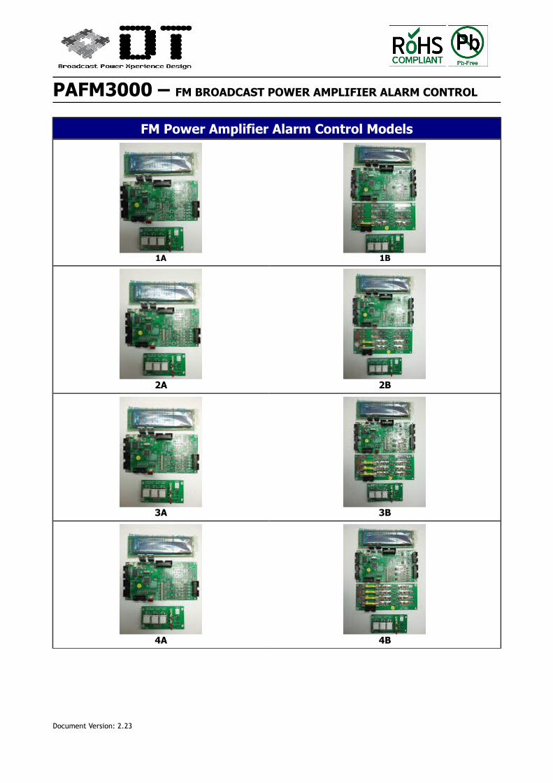
FM Power Amplifier Alarm Control Models
1A 1B
2A 2B
3A 3B
4A 4B
Document Version: 2.23
PAFM3000 – FM BROADCAST POWER AMPLIFIER ALARM CONTROL
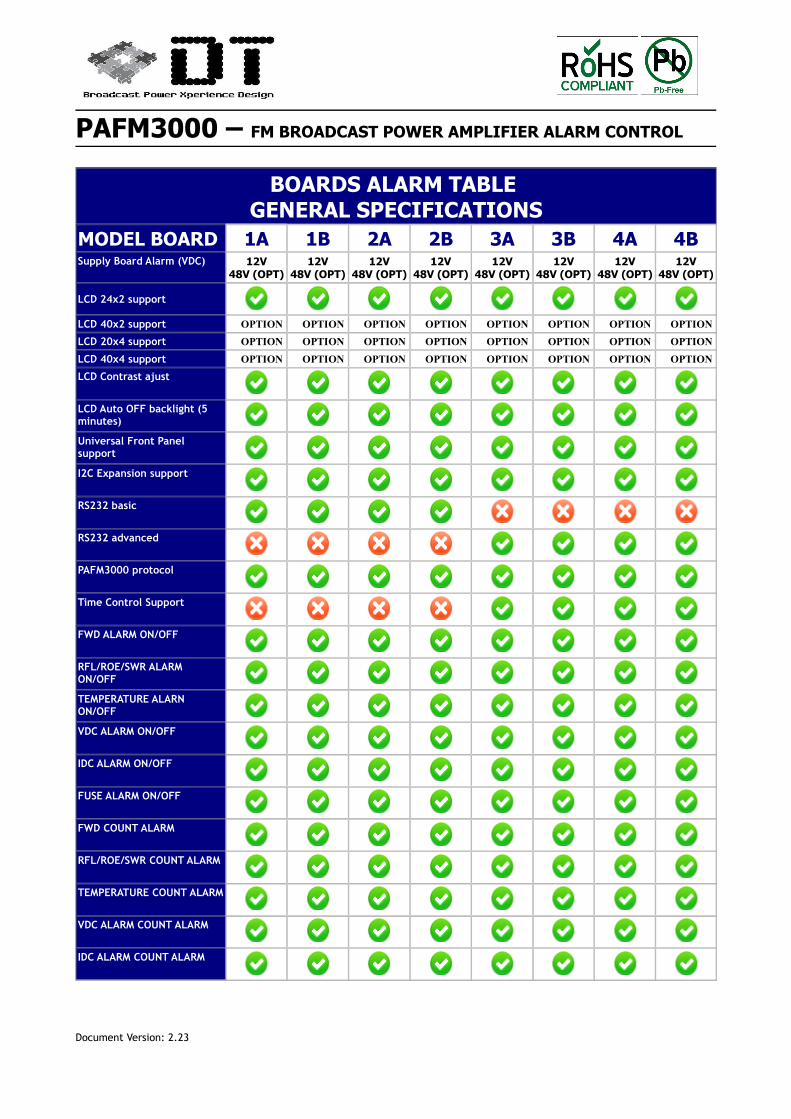
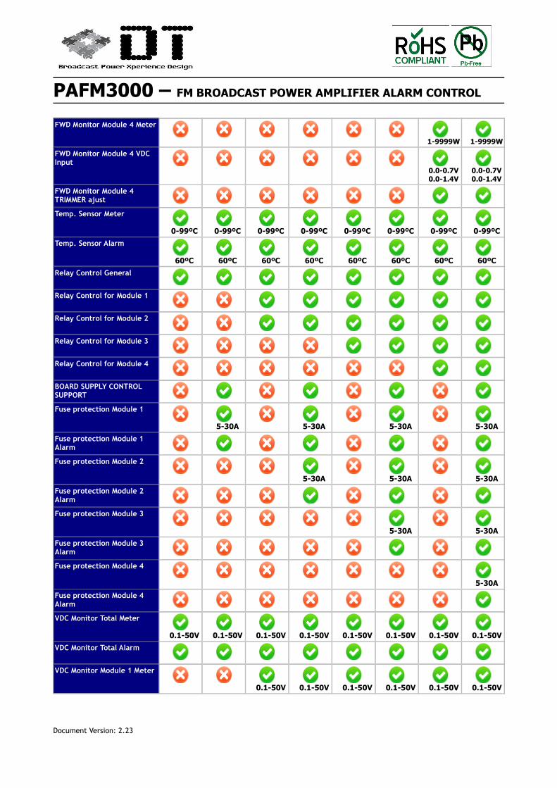
BOARDS ALARM TABLE GENERAL SPECIFICATIONS
MODEL BOARD 1A 1B 2A 2B 3A 3B 4A 4BSupply Board Alarm (VDC) 12V
48V (OPT)12V
48V (OPT)12V
48V (OPT)12V
48V (OPT)12V
48V (OPT)12V
48V (OPT)12V
48V (OPT)12V
48V (OPT)
LCD 24x2 support
LCD 40x2 support OPTION OPTION OPTION OPTION OPTION OPTION OPTION OPTION
LCD 20x4 support OPTION OPTION OPTION OPTION OPTION OPTION OPTION OPTION
LCD 40x4 support OPTION OPTION OPTION OPTION OPTION OPTION OPTION OPTION
LCD Contrast ajust
LCD Auto OFF backlight (5 minutes)
Universal Front Panel support
I2C Expansion support
RS232 basic
RS232 advanced
PAFM3000 protocol
Time Control Support
FWD ALARM ON/OFF
RFL/ROE/SWR ALARM ON/OFF
TEMPERATURE ALARN ON/OFF
VDC ALARM ON/OFF
IDC ALARM ON/OFF
FUSE ALARM ON/OFF
FWD COUNT ALARM
RFL/ROE/SWR COUNT ALARM
TEMPERATURE COUNT ALARM
VDC ALARM COUNT ALARM
IDC ALARM COUNT ALARM
Document Version: 2.23
PAFM3000 – FM BROADCAST POWER AMPLIFIER ALARM CONTROL
STARTED BOARD COUNT
RF ON/OFF Led
Alarm Led
FWD Alarm Led
RFL/ROE/SWR Alarm Led
FWD Monitor Total Meter
1-9999W 1-9999W 1-9999W 1-9999W 1-9999W 1-9999W 1-9999W 1-9999W
FWD Monitor Total VDC Input
0.0-0.7V0.0-1.4V
0.0-0.7V0.0-1.4V
0.0-0.7V0.0-1.4V
0.0-0.7V0.0-1.4V
0.0-0.7V0.0-1.4V
0.0-0.7V0.0-1.4V
0.0-0.7V0.0-1.4V
0.0-0.7V0.0-1.4V
FWD Monitor Total TRIMMER ajust
FWD Monitor Total Alarm
RFL/ROE/SWR Monitor Total Meter
RFL/ROE/SWR Total VDC Input
0.0-0.7V 0.0-0.7V 0.0-0.7V 0.0-0.7V 0.0-0.7V 0.0-0.7V 0.0-0.7V 0.0-0.7V
RFL/ROE/SWR Monitor Total TRIMMER ajust
RFL/ROE/SWR Monitor Total Alarm
FWD Monitor Module 1 Meter
1-9999W 1-9999W 1-9999W 1-9999W 1-9999W 1-9999W
FWD Monitor Module 1 VDC Input
0.0-0.7V0.0-1.4V
0.0-0.7V0.0-1.4V
0.0-0.7V0.0-1.4V
0.0-0.7V0.0-1.4V
0.0-0.7V0.0-1.4V
0.0-0.7V0.0-1.4V
FWD Monitor Module 1 TRIMMER ajust
FWD Monitor Module 2 Meter
1-9999W 1-9999W 1-9999W 1-9999W 1-9999W 1-9999W
FWD Monitor Module 2 VDC Input
0.0-0.7V0.0-1.4V
0.0-0.7V0.0-1.4V
0.0-0.7V0.0-1.4V
0.0-0.7V0.0-1.4V
0.0-0.7V0.0-1.4V
0.0-0.7V0.0-1.4V
FWD Monitor Module 2 TRIMMER ajust
FWD Monitor Module 3 Meter
1-9999W 1-9999W 1-9999W 1-9999W
FWD Monitor Module 3 VDC Input
0.0-0.7V0.0-1.4V
0.0-0.7V0.0-1.4V
0.0-0.7V0.0-1.4V
0.0-0.7V0.0-1.4V
FWD Monitor Module 3 TRIMMER ajust
Document Version: 2.23
PAFM3000 – FM BROADCAST POWER AMPLIFIER ALARM CONTROL
FWD Monitor Module 4 Meter
1-9999W 1-9999W
FWD Monitor Module 4 VDC Input
0.0-0.7V0.0-1.4V
0.0-0.7V0.0-1.4V
FWD Monitor Module 4 TRIMMER ajust
Temp. Sensor Meter
0-99ºC 0-99ºC 0-99ºC 0-99ºC 0-99ºC 0-99ºC 0-99ºC 0-99ºC
Temp. Sensor Alarm
60ºC 60ºC 60ºC 60ºC 60ºC 60ºC 60ºC 60ºC
Relay Control General
Relay Control for Module 1
Relay Control for Module 2
Relay Control for Module 3
Relay Control for Module 4
BOARD SUPPLY CONTROL SUPPORT
Fuse protection Module 1
5-30A 5-30A 5-30A 5-30A
Fuse protection Module 1 Alarm
Fuse protection Module 2
5-30A 5-30A 5-30A
Fuse protection Module 2 Alarm
Fuse protection Module 3
5-30A 5-30A
Fuse protection Module 3 Alarm
Fuse protection Module 4
5-30A
Fuse protection Module 4 Alarm
VDC Monitor Total Meter
0.1-50V 0.1-50V 0.1-50V 0.1-50V 0.1-50V 0.1-50V 0.1-50V 0.1-50V
VDC Monitor Total Alarm
VDC Monitor Module 1 Meter
0.1-50V 0.1-50V 0.1-50V 0.1-50V 0.1-50V 0.1-50V
Document Version: 2.23
PAFM3000 – FM BROADCAST POWER AMPLIFIER ALARM CONTROL
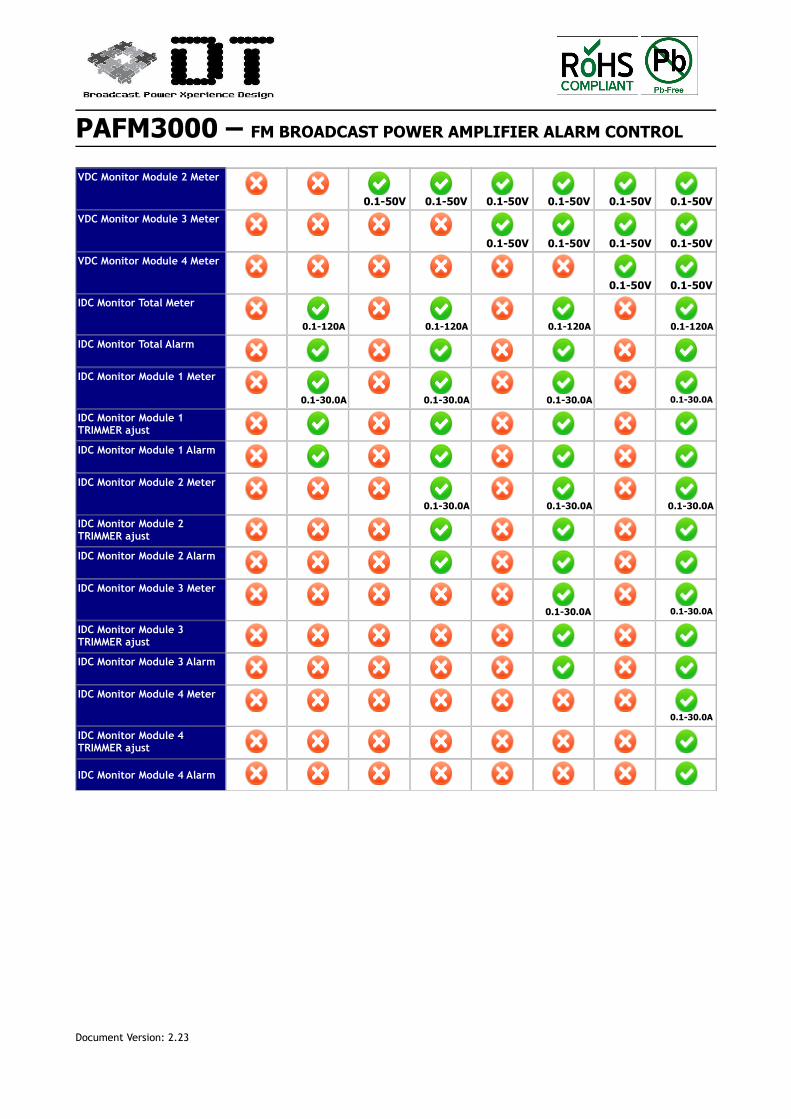
VDC Monitor Module 2 Meter
0.1-50V 0.1-50V 0.1-50V 0.1-50V 0.1-50V 0.1-50V
VDC Monitor Module 3 Meter
0.1-50V 0.1-50V 0.1-50V 0.1-50V
VDC Monitor Module 4 Meter
0.1-50V 0.1-50V
IDC Monitor Total Meter
0.1-120A 0.1-120A 0.1-120A 0.1-120A
IDC Monitor Total Alarm
IDC Monitor Module 1 Meter
0.1-30.0A 0.1-30.0A 0.1-30.0A 0.1-30.0A
IDC Monitor Module 1 TRIMMER ajust
IDC Monitor Module 1 Alarm
IDC Monitor Module 2 Meter
0.1-30.0A 0.1-30.0A 0.1-30.0A
IDC Monitor Module 2 TRIMMER ajust
IDC Monitor Module 2 Alarm
IDC Monitor Module 3 Meter
0.1-30.0A 0.1-30.0A
IDC Monitor Module 3 TRIMMER ajust
IDC Monitor Module 3 Alarm
IDC Monitor Module 4 Meter
0.1-30.0A
IDC Monitor Module 4 TRIMMER ajust
IDC Monitor Module 4 Alarm
Document Version: 2.23
PAFM3000 – FM BROADCAST POWER AMPLIFIER ALARM CONTROL
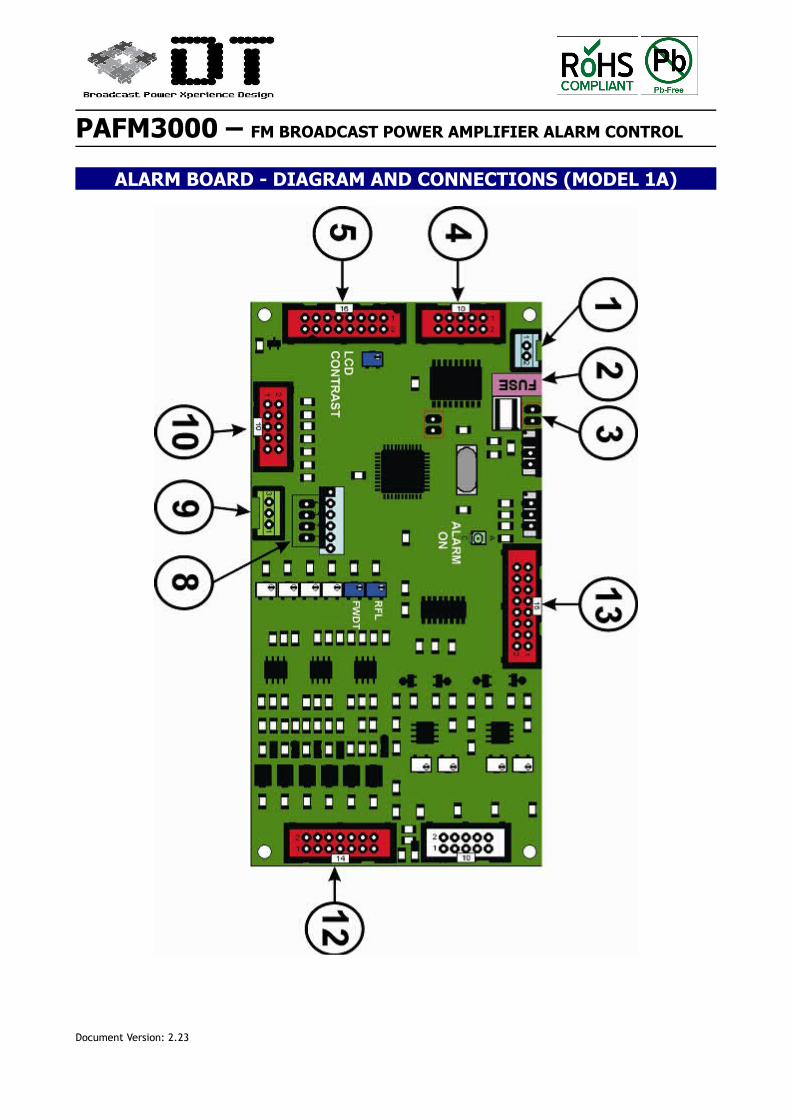
ALARM BOARD - DIAGRAM AND CONNECTIONS (MODEL 1A)
Document Version: 2.23
PAFM3000 – FM BROADCAST POWER AMPLIFIER ALARM CONTROL
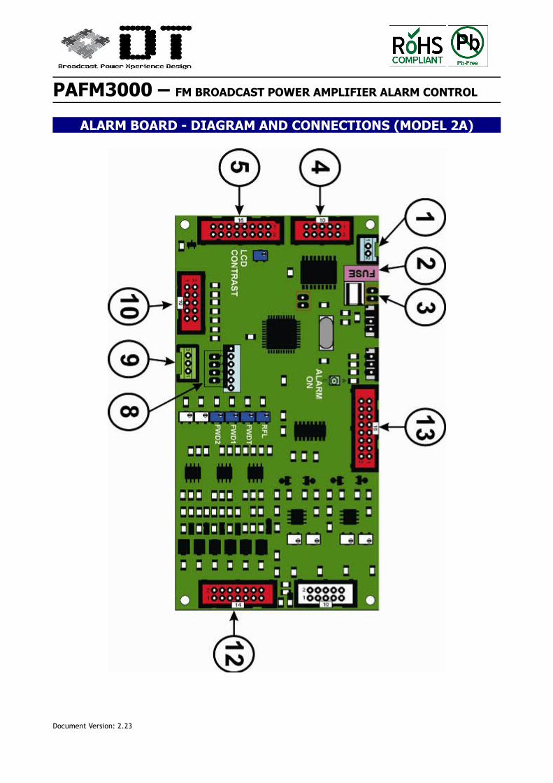
ALARM BOARD - DIAGRAM AND CONNECTIONS (MODEL 2A)
Document Version: 2.23
PAFM3000 – FM BROADCAST POWER AMPLIFIER ALARM CONTROL
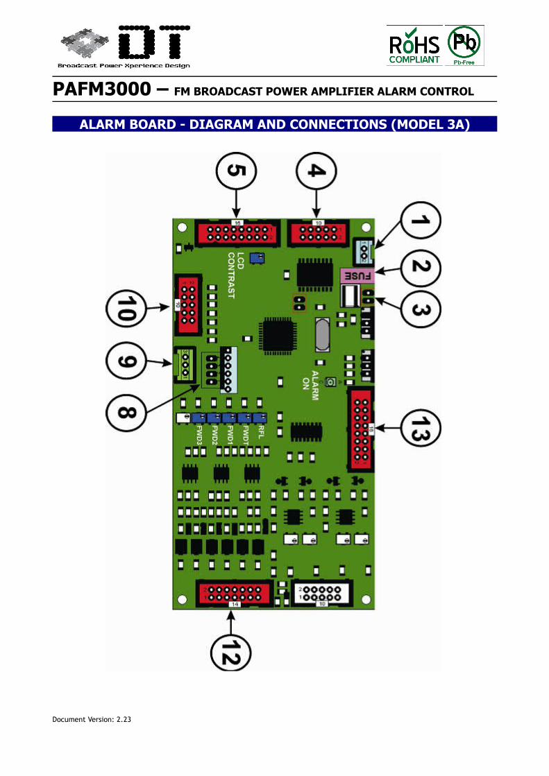
ALARM BOARD - DIAGRAM AND CONNECTIONS (MODEL 3A)
Document Version: 2.23
PAFM3000 – FM BROADCAST POWER AMPLIFIER ALARM CONTROL
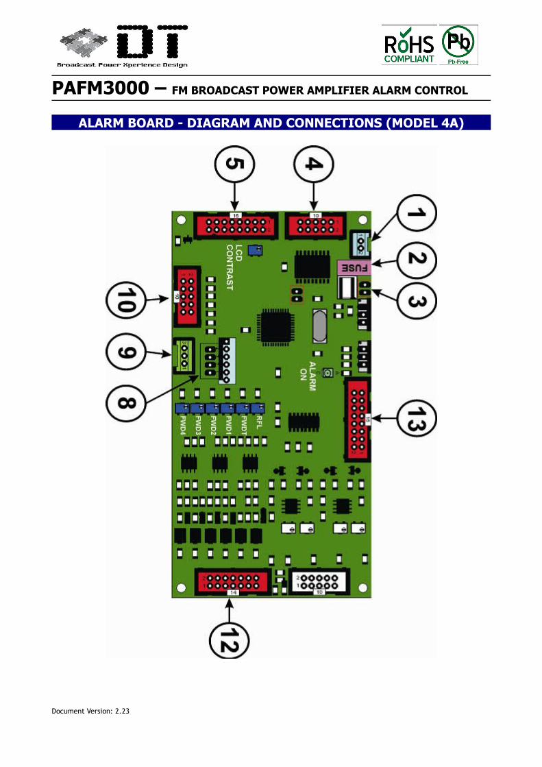
ALARM BOARD - DIAGRAM AND CONNECTIONS (MODEL 4A)
Document Version: 2.23
PAFM3000 – FM BROADCAST POWER AMPLIFIER ALARM CONTROL
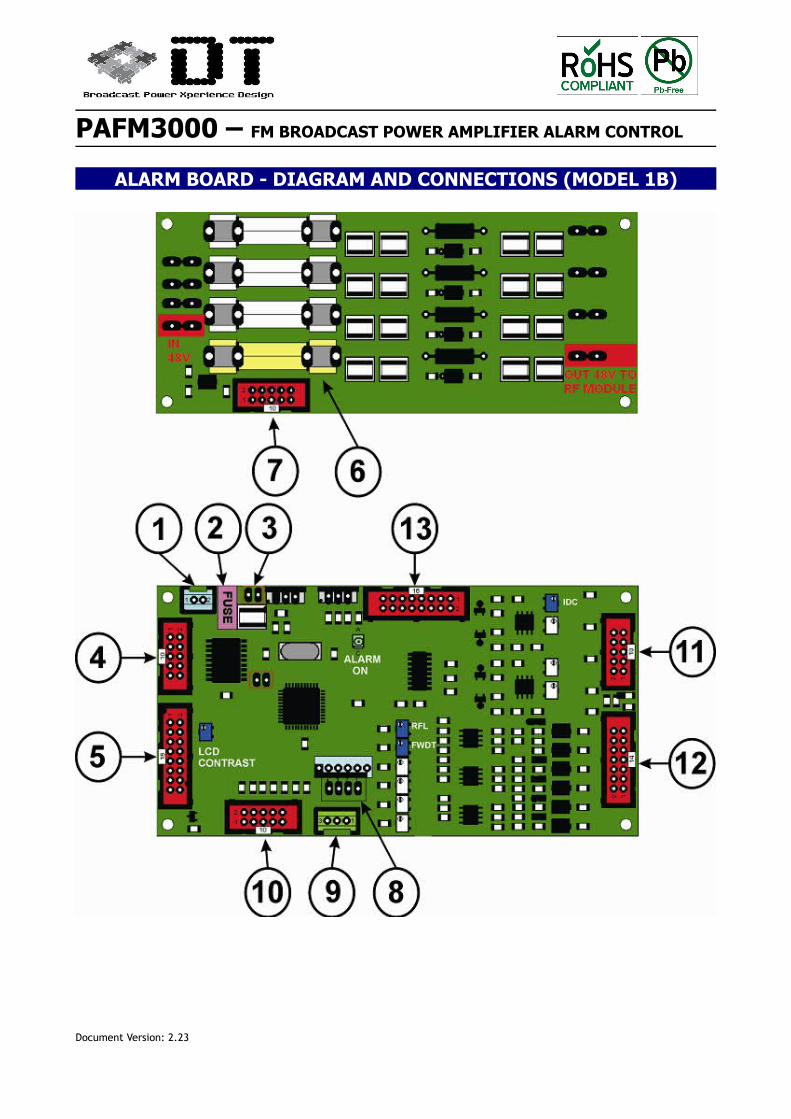
ALARM BOARD - DIAGRAM AND CONNECTIONS (MODEL 1B)
Document Version: 2.23
PAFM3000 – FM BROADCAST POWER AMPLIFIER ALARM CONTROL
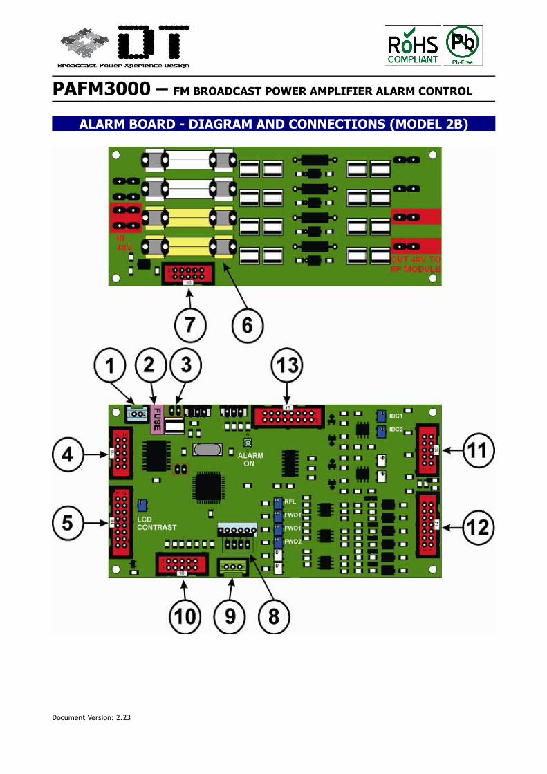
ALARM BOARD - DIAGRAM AND CONNECTIONS (MODEL 2B)
Document Version: 2.23
PAFM3000 – FM BROADCAST POWER AMPLIFIER ALARM CONTROL
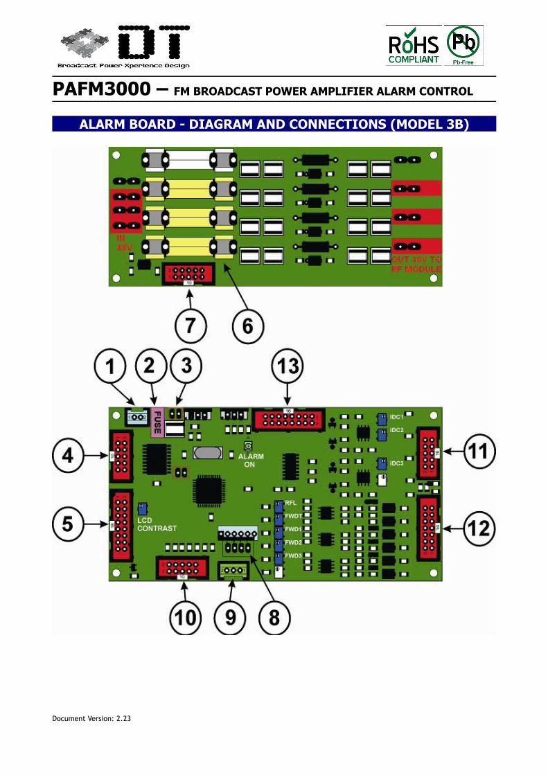
ALARM BOARD - DIAGRAM AND CONNECTIONS (MODEL 3B)
Document Version: 2.23
PAFM3000 – FM BROADCAST POWER AMPLIFIER ALARM CONTROL
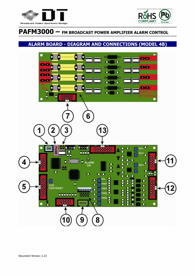
ALARM BOARD - DIAGRAM AND CONNECTIONS (MODEL 4B)
Document Version: 2.23
PAFM3000 – FM BROADCAST POWER AMPLIFIER ALARM CONTROL
ALARM BOARDS - CONNECTIONS DETAILS
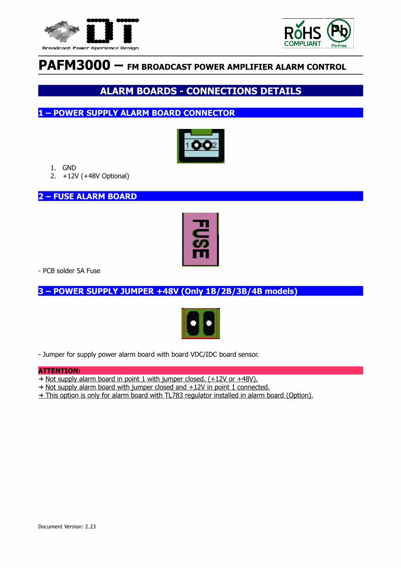
1 – POWER SUPPLY ALARM BOARD CONNECTOR
1. GND2. +12V (+48V Optional)
2 – FUSE ALARM BOARD
- PCB solder 5A Fuse
3 – POWER SUPPLY JUMPER +48V (Only 1B/2B/3B/4B models)
- Jumper for supply power alarm board with board VDC/IDC board sensor.
ATTENTION: → Not supply alarm board in point 1 with jumper closed. (+12V or +48V). → Not supply alarm board with jumper closed and +12V in point 1 connected. This option is only for alarm board with TL783 regulator installed in alarm board → (Option) .
Document Version: 2.23
PAFM3000 – FM BROADCAST POWER AMPLIFIER ALARM CONTROL
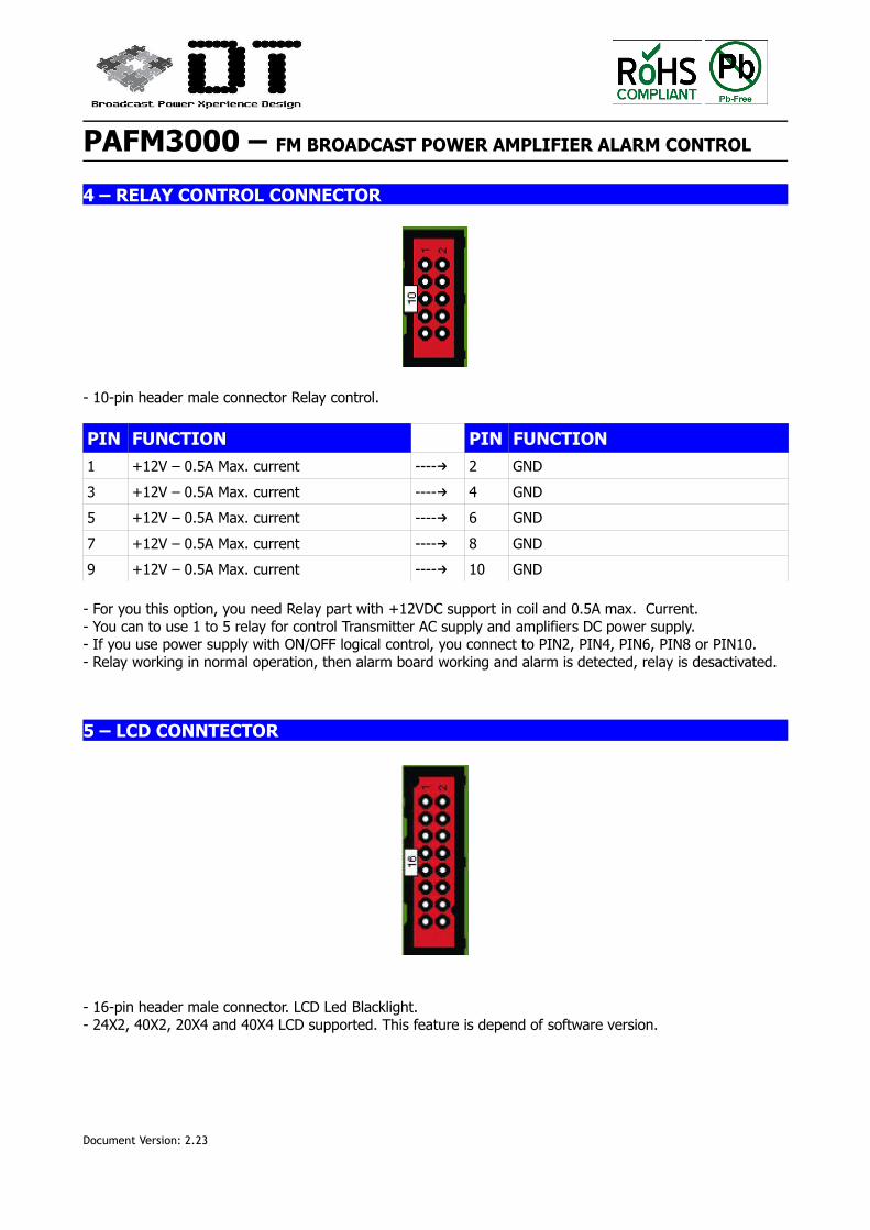
4 – RELAY CONTROL CONNECTOR
- 10-pin header male connector Relay control.
PIN FUNCTION PIN FUNCTION1 +12V – 0.5A Max. current ----→ 2 GND
3 +12V – 0.5A Max. current ----→ 4 GND
5 +12V – 0.5A Max. current ----→ 6 GND
7 +12V – 0.5A Max. current ----→ 8 GND
9 +12V – 0.5A Max. current ----→ 10 GND
- For you this option, you need Relay part with +12VDC support in coil and 0.5A max. Current.- You can to use 1 to 5 relay for control Transmitter AC supply and amplifiers DC power supply.- If you use power supply with ON/OFF logical control, you connect to PIN2, PIN4, PIN6, PIN8 or PIN10.- Relay working in normal operation, then alarm board working and alarm is detected, relay is desactivated.
5 – LCD CONNTECTOR
- 16-pin header male connector. LCD Led Blacklight.- 24X2, 40X2, 20X4 and 40X4 LCD supported. This feature is depend of software version.
Document Version: 2.23
PAFM3000 – FM BROADCAST POWER AMPLIFIER ALARM CONTROL
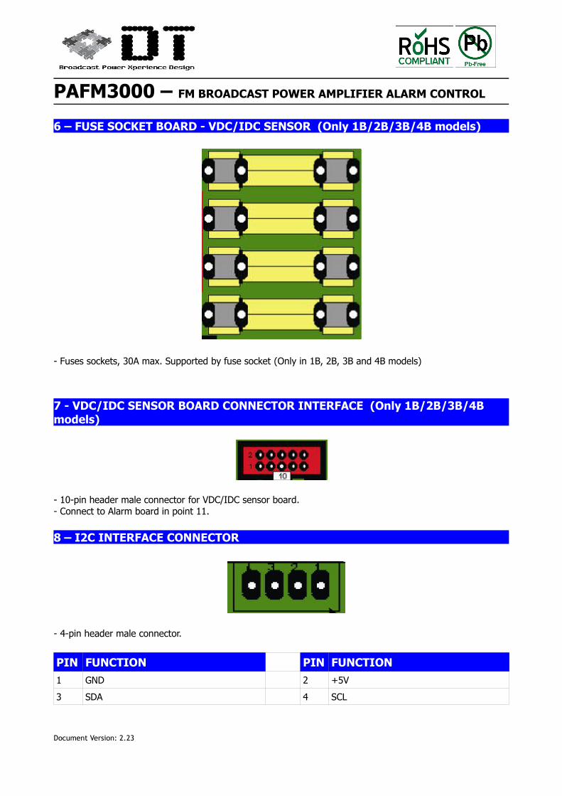
6 – FUSE SOCKET BOARD - VDC/IDC SENSOR (Only 1B/2B/3B/4B models)
- Fuses sockets, 30A max. Supported by fuse socket (Only in 1B, 2B, 3B and 4B models)
7 - VDC/IDC SENSOR BOARD CONNECTOR INTERFACE (Only 1B/2B/3B/4B models)
- 10-pin header male connector for VDC/IDC sensor board.- Connect to Alarm board in point 11.
8 – I2C INTERFACE CONNECTOR
- 4-pin header male connector.
PIN FUNCTION PIN FUNCTION1 GND 2 +5V
3 SDA 4 SCL
Document Version: 2.23
PAFM3000 – FM BROADCAST POWER AMPLIFIER ALARM CONTROL
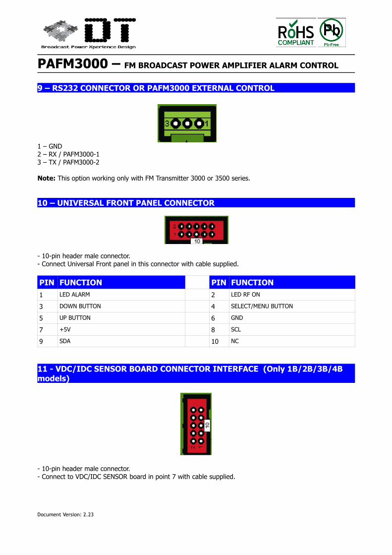
9 – RS232 CONNECTOR OR PAFM3000 EXTERNAL CONTROL
1 – GND2 – RX / PAFM3000-13 – TX / PAFM3000-2
Note: This option working only with FM Transmitter 3000 or 3500 series.
10 – UNIVERSAL FRONT PANEL CONNECTOR
- 10-pin header male connector.- Connect Universal Front panel in this connector with cable supplied.
PIN FUNCTION PIN FUNCTION1 LED ALARM 2 LED RF ON
3 DOWN BUTTON 4 SELECT/MENU BUTTON
5 UP BUTTON 6 GND
7 +5V 8 SCL
9 SDA 10 NC
11 - VDC/IDC SENSOR BOARD CONNECTOR INTERFACE (Only 1B/2B/3B/4B models)
- 10-pin header male connector.- Connect to VDC/IDC SENSOR board in point 7 with cable supplied.
Document Version: 2.23
PAFM3000 – FM BROADCAST POWER AMPLIFIER ALARM CONTROL
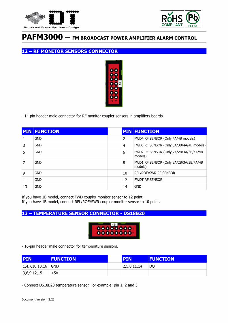
12 – RF MONITOR SENSORS CONNECTOR
- 14-pin header male connector for RF monitor coupler sensors in amplifiers boards
PIN FUNCTION PIN FUNCTION
1 GND 2 FWD4 RF SENSOR (Only 4A/4B models)
3 GND 4 FWD3 RF SENSOR (Only 3A/3B/4A/4B models)
5 GND 6 FWD2 RF SENSOR (Only 2A/2B/3A/3B/4A/4B models)
7 GND 8 FWD1 RF SENSOR (Only 2A/2B/3A/3B/4A/4B models)
9 GND 10 RFL/ROE/SWR RF SENSOR
11 GND 12 FWDT RF SENSOR
13 GND 14 GND
If you have 1B model, connect FWD coupler monitor sensor to 12 point.If you have 1B model, connect RFL/ROE/SWR coupler monitor sensor to 10 point.
13 – TEMPERATURE SENSOR CONNECTOR - DS18B20
- 16-pin header male connector for temperature sensors.
PIN FUNCTION PIN FUNCTION
1,4,7,10,13,16 GND 2,5,8,11,14 DQ
3,6,9,12,15 +5V
- Connect DS18B20 temperature sensor. For example: pin 1, 2 and 3.
Document Version: 2.23
PAFM3000 – FM BROADCAST POWER AMPLIFIER ALARM CONTROL
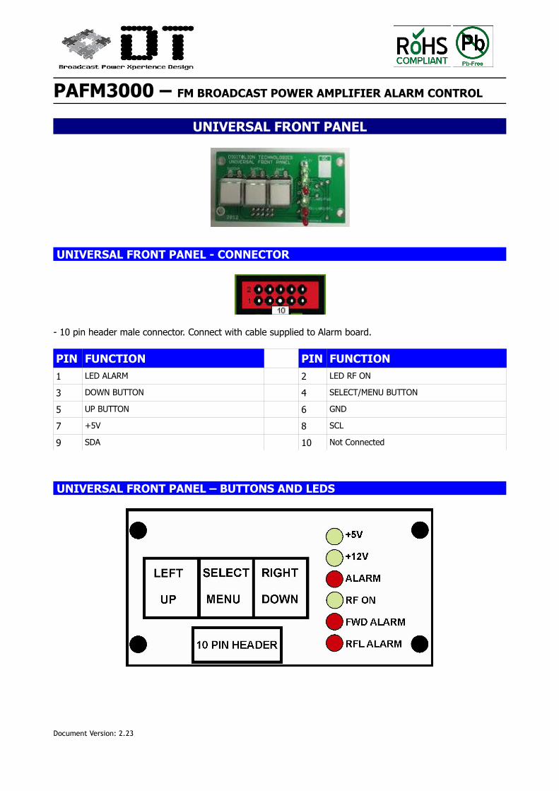
UNIVERSAL FRONT PANEL
UNIVERSAL FRONT PANEL - CONNECTOR
- 10 pin header male connector. Connect with cable supplied to Alarm board.
PIN FUNCTION PIN FUNCTION
1 LED ALARM 2 LED RF ON
3 DOWN BUTTON 4 SELECT/MENU BUTTON
5 UP BUTTON 6 GND
7 +5V 8 SCL
9 SDA 10 Not Connected
UNIVERSAL FRONT PANEL – BUTTONS AND LEDS
Document Version: 2.23
PAFM3000 – FM BROADCAST POWER AMPLIFIER ALARM CONTROL
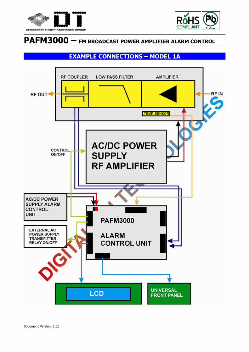
EXAMPLE CONNECTIONS – MODEL 1A
Document Version: 2.23
PAFM3000 – FM BROADCAST POWER AMPLIFIER ALARM CONTROL
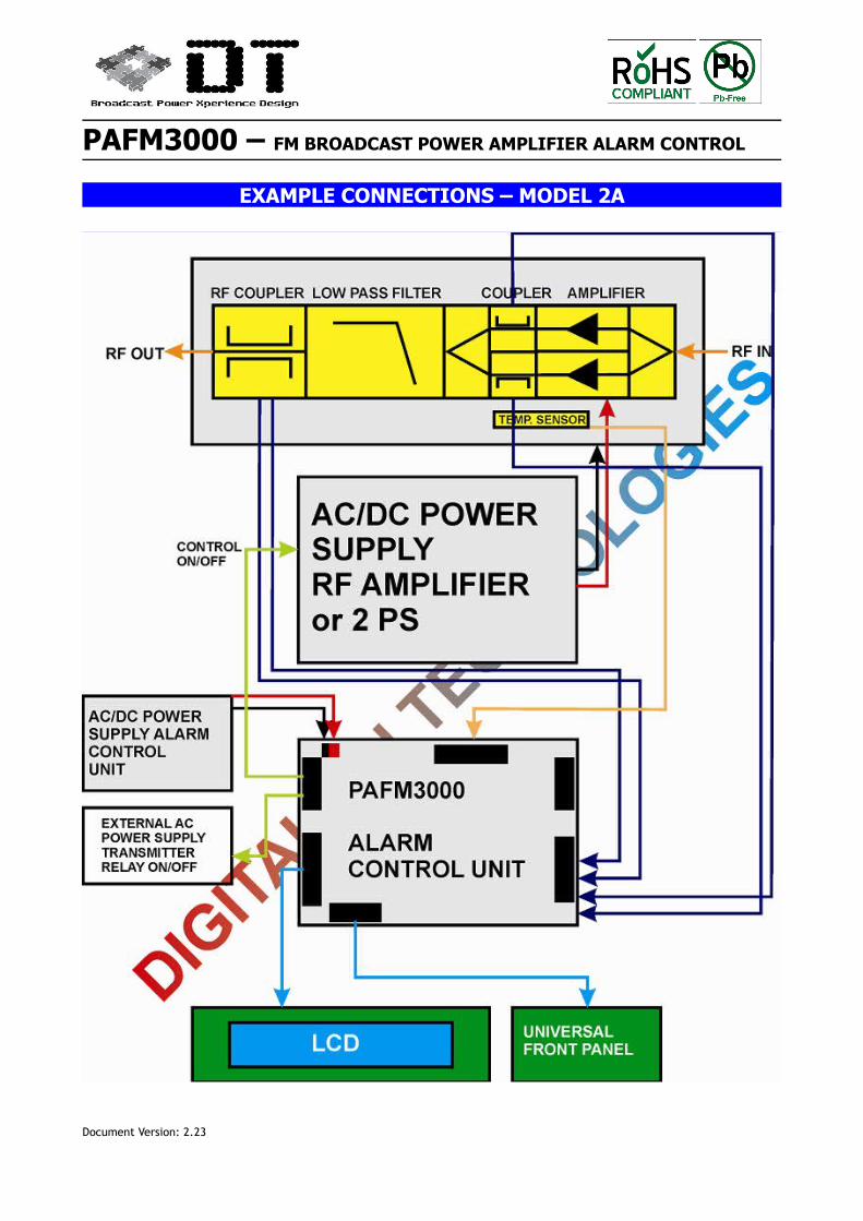
EXAMPLE CONNECTIONS – MODEL 2A
Document Version: 2.23
PAFM3000 – FM BROADCAST POWER AMPLIFIER ALARM CONTROL
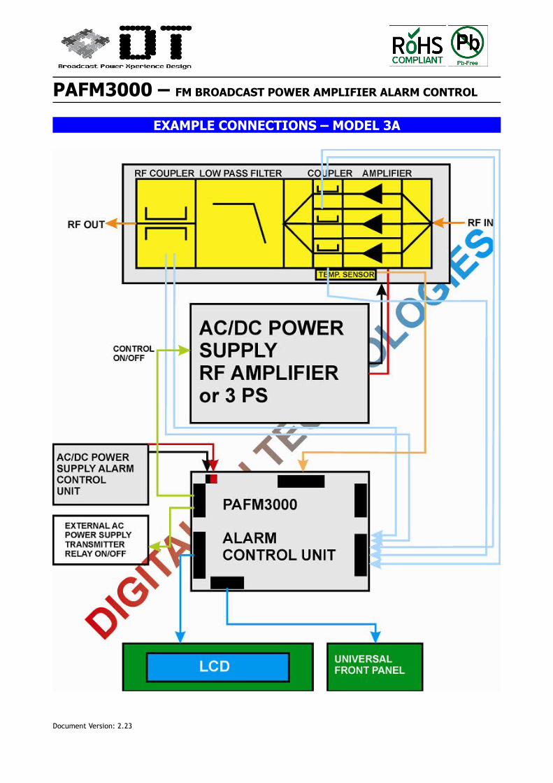
EXAMPLE CONNECTIONS – MODEL 3A
Document Version: 2.23
PAFM3000 – FM BROADCAST POWER AMPLIFIER ALARM CONTROL
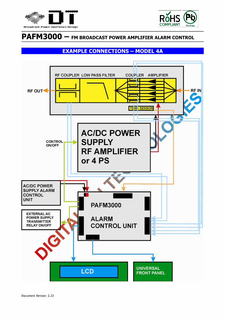
EXAMPLE CONNECTIONS – MODEL 4A
Document Version: 2.23
PAFM3000 – FM BROADCAST POWER AMPLIFIER ALARM CONTROL
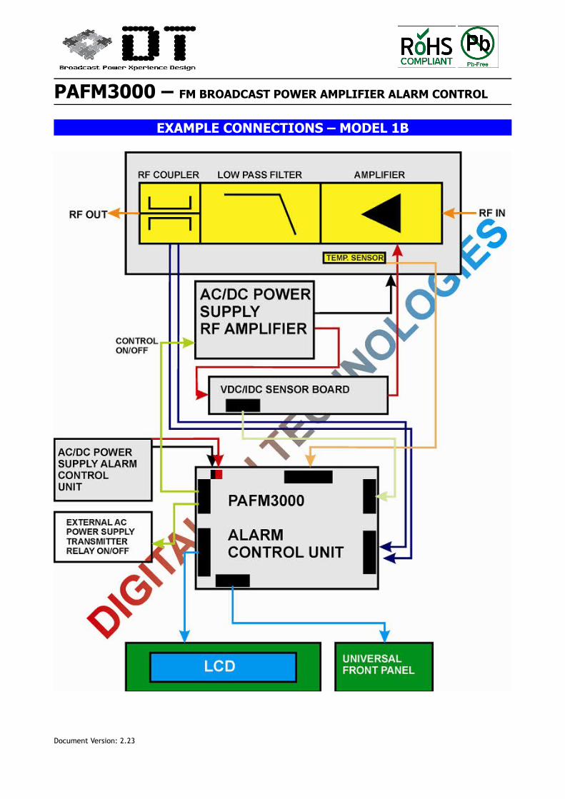
EXAMPLE CONNECTIONS – MODEL 1B
Document Version: 2.23
PAFM3000 – FM BROADCAST POWER AMPLIFIER ALARM CONTROL
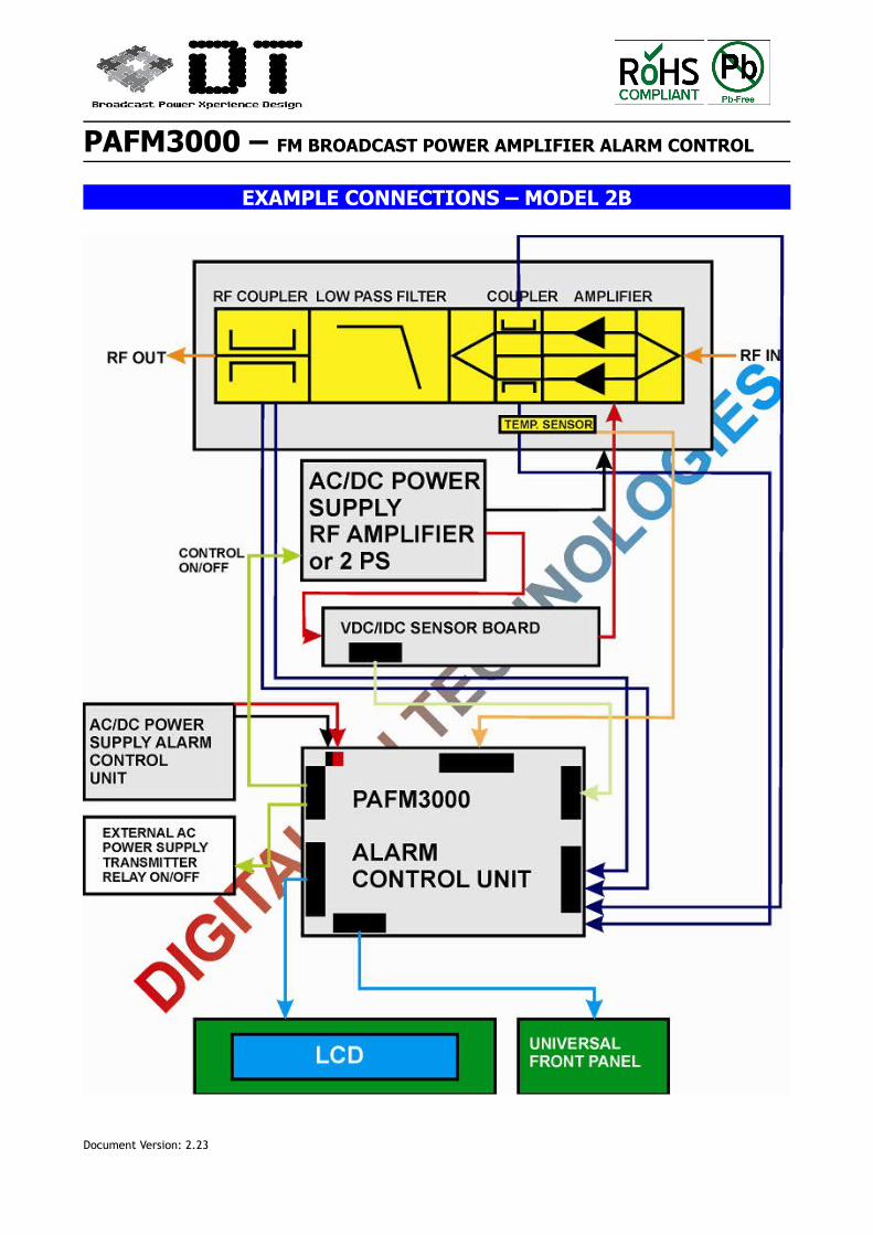
EXAMPLE CONNECTIONS – MODEL 2B
Document Version: 2.23
PAFM3000 – FM BROADCAST POWER AMPLIFIER ALARM CONTROL
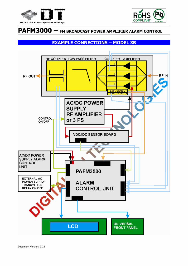
EXAMPLE CONNECTIONS – MODEL 3B
Document Version: 2.23
PAFM3000 – FM BROADCAST POWER AMPLIFIER ALARM CONTROL
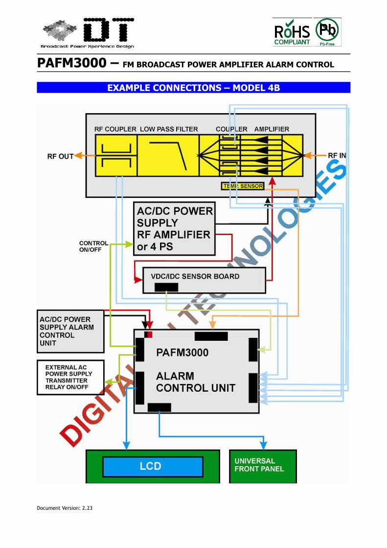
EXAMPLE CONNECTIONS – MODEL 4B
Document Version: 2.23
PAFM3000 – FM BROADCAST POWER AMPLIFIER ALARM CONTROL
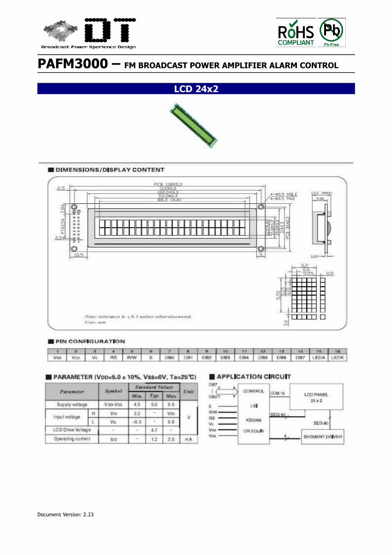
LCD 24x2
Document Version: 2.23
PAFM3000 – FM BROADCAST POWER AMPLIFIER ALARM CONTROL
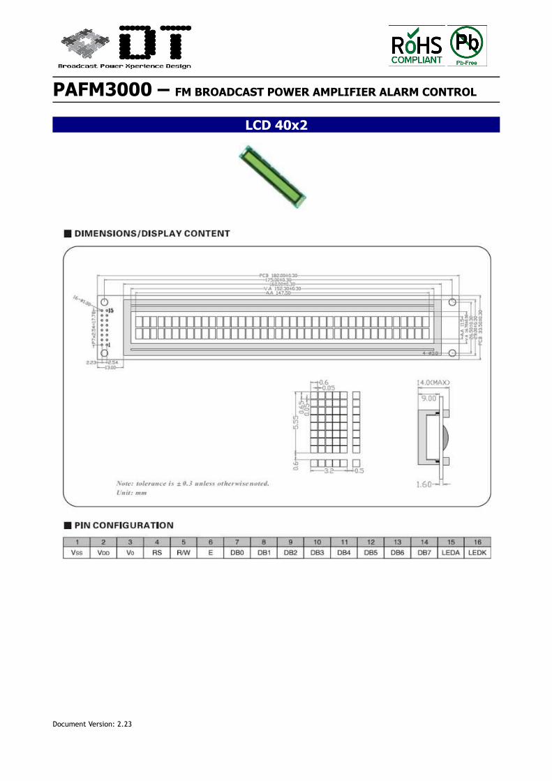
LCD 40x2
Document Version: 2.23
PAFM3000 – FM BROADCAST POWER AMPLIFIER ALARM CONTROL
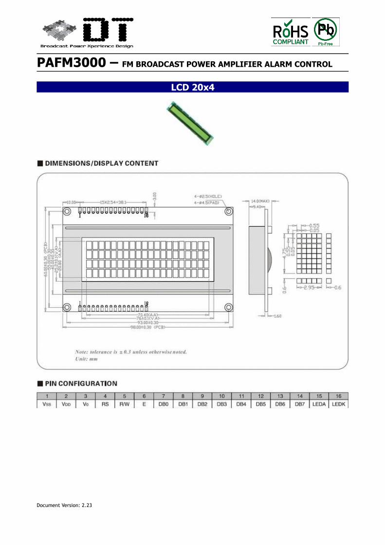
LCD 20x4
Document Version: 2.23
PAFM3000 – FM BROADCAST POWER AMPLIFIER ALARM CONTROL
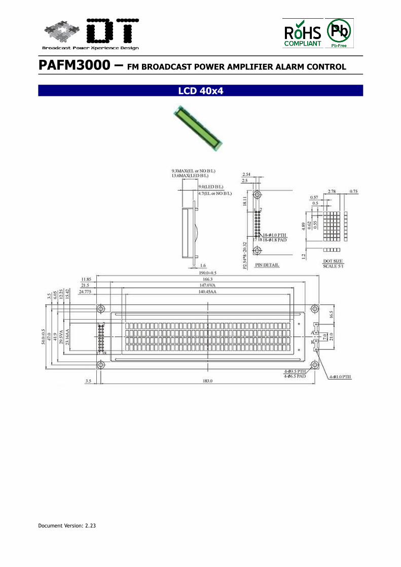
LCD 40x4
Document Version: 2.23
PAFM3000 – FM BROADCAST POWER AMPLIFIER ALARM CONTROL
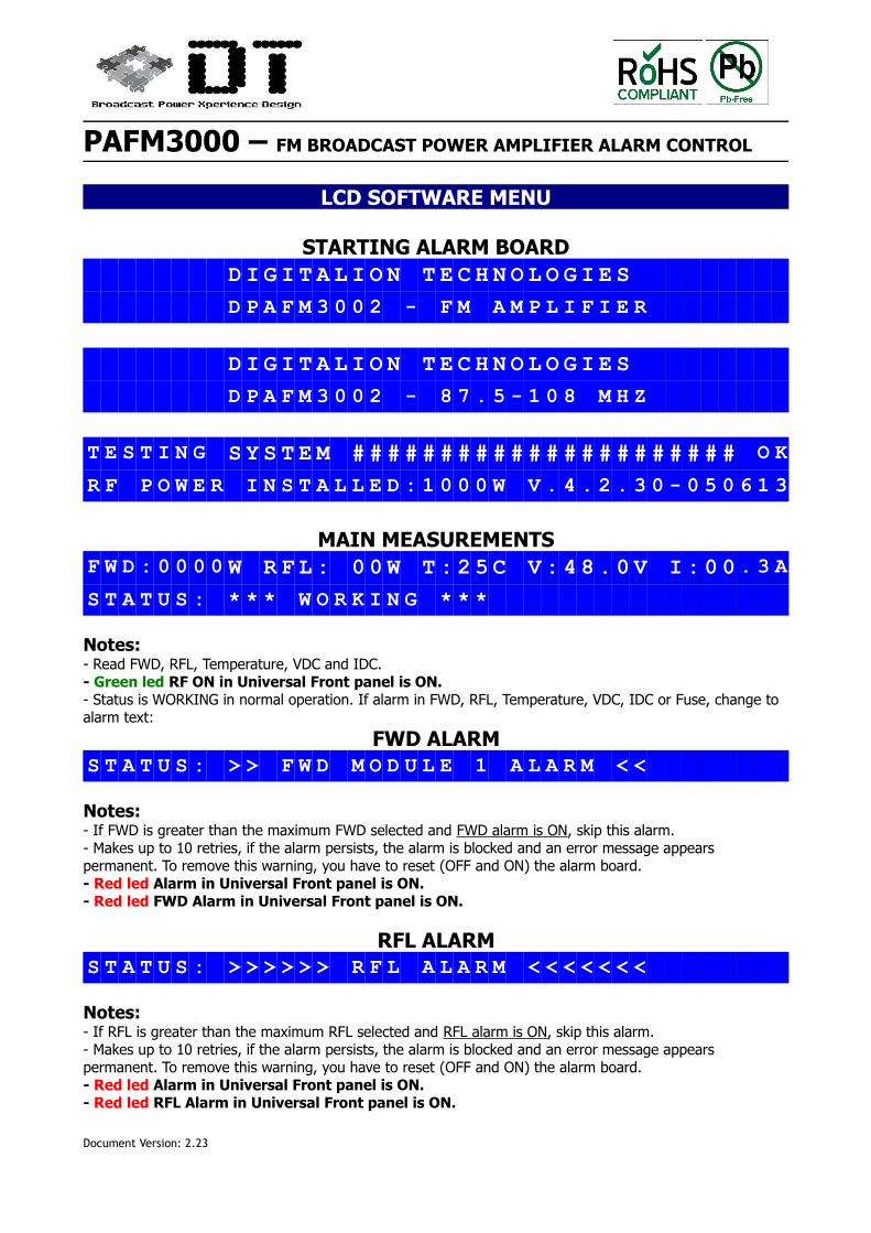
LCD SOFTWARE MENU
STARTING ALARM BOARDD I G I T A L I O N T E C H N O L O G I E S
D P A F M 3 0 0 2 - F M A M P L I F I E R
D I G I T A L I O N T E C H N O L O G I E S
D P A F M 3 0 0 2 - 8 7 . 5 - 1 0 8 M H Z
T E S T I N G S Y S T E M # # # # # # # # # # # # # # # # # # # # # # O K
R F P O W E R I N S T A L L E D : 1 0 0 0 W V . 4 . 2 . 3 0 - 0 5 0 6 1 3
MAIN MEASUREMENTSF W D : 0 0 0 0 W R F L : 0 0 W T : 2 5 C V : 4 8 . 0 V I : 0 0 . 3 A
S T A T U S : * * * W O R K I N G * * *
Notes:- Read FWD, RFL, Temperature, VDC and IDC.- Green led RF ON in Universal Front panel is ON.- Status is WORKING in normal operation. If alarm in FWD, RFL, Temperature, VDC, IDC or Fuse, change to alarm text:
FWD ALARMS T A T U S : > > F W D M O D U L E 1 A L A R M < <
Notes:- If FWD is greater than the maximum FWD selected and FWD alarm is ON, skip this alarm. - Makes up to 10 retries, if the alarm persists, the alarm is blocked and an error message appears permanent. To remove this warning, you have to reset (OFF and ON) the alarm board.- Red led Alarm in Universal Front panel is ON.- Red led FWD Alarm in Universal Front panel is ON.
RFL ALARMS T A T U S : > > > > > > R F L A L A R M < < < < < < <
Notes:- If RFL is greater than the maximum RFL selected and RFL alarm is ON, skip this alarm. - Makes up to 10 retries, if the alarm persists, the alarm is blocked and an error message appears permanent. To remove this warning, you have to reset (OFF and ON) the alarm board.- Red led Alarm in Universal Front panel is ON.- Red led RFL Alarm in Universal Front panel is ON.
Document Version: 2.23
PAFM3000 – FM BROADCAST POWER AMPLIFIER ALARM CONTROL
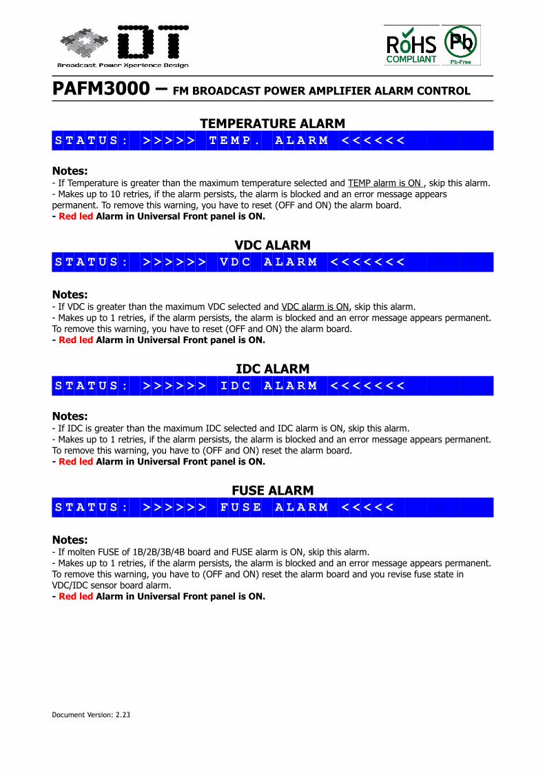
TEMPERATURE ALARMS T A T U S : > > > > > T E M P . A L A R M < < < < < <
Notes:- If Temperature is greater than the maximum temperature selected and TEMP alarm is ON , skip this alarm. - Makes up to 10 retries, if the alarm persists, the alarm is blocked and an error message appears permanent. To remove this warning, you have to reset (OFF and ON) the alarm board.- Red led Alarm in Universal Front panel is ON.
VDC ALARMS T A T U S : > > > > > > V D C A L A R M < < < < < < <
Notes:- If VDC is greater than the maximum VDC selected and VDC alarm is ON, skip this alarm. - Makes up to 1 retries, if the alarm persists, the alarm is blocked and an error message appears permanent.To remove this warning, you have to reset (OFF and ON) the alarm board.- Red led Alarm in Universal Front panel is ON.
IDC ALARMS T A T U S : > > > > > > I D C A L A R M < < < < < < <
Notes:- If IDC is greater than the maximum IDC selected and IDC alarm is ON, skip this alarm. - Makes up to 1 retries, if the alarm persists, the alarm is blocked and an error message appears permanent.To remove this warning, you have to (OFF and ON) reset the alarm board.- Red led Alarm in Universal Front panel is ON.
FUSE ALARMS T A T U S : > > > > > > F U S E A L A R M < < < < <
Notes:- If molten FUSE of 1B/2B/3B/4B board and FUSE alarm is ON, skip this alarm. - Makes up to 1 retries, if the alarm persists, the alarm is blocked and an error message appears permanent.To remove this warning, you have to (OFF and ON) reset the alarm board and you revise fuse state in VDC/IDC sensor board alarm.- Red led Alarm in Universal Front panel is ON.
Document Version: 2.23
PAFM3000 – FM BROADCAST POWER AMPLIFIER ALARM CONTROL
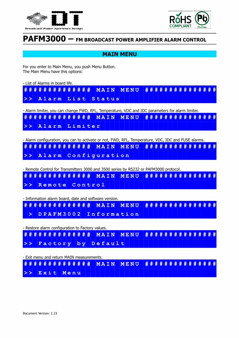
MAIN MENU
For you enter to Main Menu, you push Menu Button.The Main Menu have this options:
- List of Alarms in board life.
# # # # # # # # # # # # # # M A I N M E N U # # # # # # # # # # # # # # #
> > A l a r m L i s t S t a t u s
- Alarm limiter, you can change FWD, RFL, Temperature, VDC and IDC parameters for alarm limiter.
# # # # # # # # # # # # # # M A I N M E N U # # # # # # # # # # # # # # #
> > A l a r m L i m i t e r
- Alarm configuration, you can to activate or not, FWD, RFL, Temperature, VDC, IDC and FUSE alarms.
# # # # # # # # # # # # # # M A I N M E N U # # # # # # # # # # # # # # #
> > A l a r m C o n f i g u r a t i o n
- Remote Control for Transmitters 3000 and 3500 series by RS232 or PAFM3000 protocol.
# # # # # # # # # # # # # # M A I N M E N U # # # # # # # # # # # # # # #
> > R e m o t e C o n t r o l
- Information alarm board, date and software version.
# # # # # # # # # # # # # # M A I N M E N U # # # # # # # # # # # # # # #
> D P A F M 3 0 0 2 I n f o r m a t i o n
- Restore alarm configuration to Factory values.
# # # # # # # # # # # # # # M A I N M E N U # # # # # # # # # # # # # # #
> > F a c t o r y b y D e f a u l t
- Exit menu and return MAIN measurements.
# # # # # # # # # # # # # # M A I N M E N U # # # # # # # # # # # # # # #
> > E x i t M e n u
Document Version: 2.23
PAFM3000 – FM BROADCAST POWER AMPLIFIER ALARM CONTROL
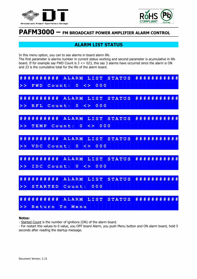
ALARM LIST STATUS
In this menu option, you can to see alarms in board alarm life. The first parameter is alarms number in current status working and second parameter is acumulative in life board. If for example say FWD Count is 3 <> 023, this say 3 alarms have occurred since the alarm is ON and 23 is the cumulative total for the life of the alarm board.
# # # # # # # # # # A L A R M L I S T S T A T U S # # # # # # # # # # #
> > F W D C o u n t : 0 < > 0 0 0
# # # # # # # # # # A L A R M L I S T S T A T U S # # # # # # # # # # #
> > R F L C o u n t : 0 < > 0 0 0
# # # # # # # # # # A L A R M L I S T S T A T U S # # # # # # # # # # #
> > T E M P C o u n t : 0 < > 0 0 0
# # # # # # # # # # A L A R M L I S T S T A T U S # # # # # # # # # # #
> > V D C C o u n t : 0 < > 0 0 0
# # # # # # # # # # A L A R M L I S T S T A T U S # # # # # # # # # # #
> > I D C C o u n t : 0 < > 0 0 0
# # # # # # # # # # A L A R M L I S T S T A T U S # # # # # # # # # # #
> > S T A R T E D C o u n t : 0 0 0
# # # # # # # # # # A L A R M L I S T S T A T U S # # # # # # # # # # #
> > R e t u r n T o M e n u
Notes:- Started Count is the number of ignitions (ON) of the alarm board.- For restart this values to 0 value, you OFF board Alarm, you push Menu button and ON alarm board, hold 5seconds after reading the startup message.
Document Version: 2.23
PAFM3000 – FM BROADCAST POWER AMPLIFIER ALARM CONTROL
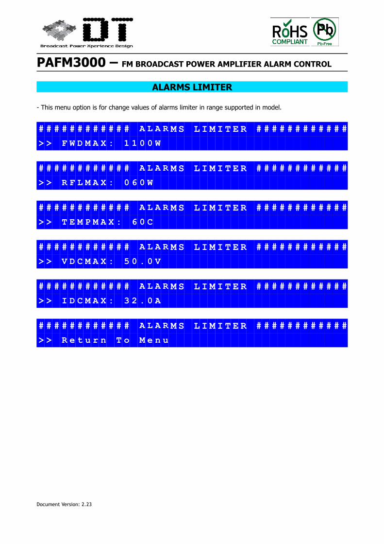
ALARMS LIMITER
- This menu option is for change values of alarms limiter in range supported in model.
# # # # # # # # # # # # A L A R M S L I M I T E R # # # # # # # # # # # #
> > F W D M A X : 1 1 0 0 W
# # # # # # # # # # # # A L A R M S L I M I T E R # # # # # # # # # # # #
> > R F L M A X : 0 6 0 W
# # # # # # # # # # # # A L A R M S L I M I T E R # # # # # # # # # # # #
> > T E M P M A X : 6 0 C
# # # # # # # # # # # # A L A R M S L I M I T E R # # # # # # # # # # # #
> > V D C M A X : 5 0 . 0 V
# # # # # # # # # # # # A L A R M S L I M I T E R # # # # # # # # # # # #
> > I D C M A X : 3 2 . 0 A
# # # # # # # # # # # # A L A R M S L I M I T E R # # # # # # # # # # # #
> > R e t u r n T o M e n u
Document Version: 2.23
PAFM3000 – FM BROADCAST POWER AMPLIFIER ALARM CONTROL
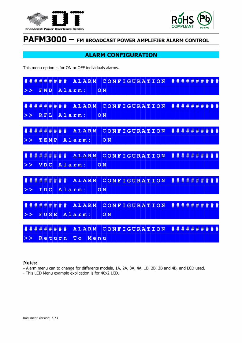
ALARM CONFIGURATION
This menu option is for ON or OFF individuals alarms.
# # # # # # # # # A L A R M C O N F I G U R A T I O N # # # # # # # # # #
> > F W D A l a r m : O N
# # # # # # # # # A L A R M C O N F I G U R A T I O N # # # # # # # # # #
> > R F L A l a r m : O N
# # # # # # # # # A L A R M C O N F I G U R A T I O N # # # # # # # # # #
> > T E M P A l a r m : O N
# # # # # # # # # A L A R M C O N F I G U R A T I O N # # # # # # # # # #
> > V D C A l a r m : O N
# # # # # # # # # A L A R M C O N F I G U R A T I O N # # # # # # # # # #
> > I D C A l a r m : O N
# # # # # # # # # A L A R M C O N F I G U R A T I O N # # # # # # # # # #
> > F U S E A l a r m : O N
# # # # # # # # # A L A R M C O N F I G U R A T I O N # # # # # # # # # #
> > R e t u r n T o M e n u
Notes:- Alarm menu can to change for differents models, 1A, 2A, 3A, 4A, 1B, 2B, 3B and 4B, and LCD used.- This LCD Menu example explication is for 40x2 LCD.
Document Version: 2.23
PAFM3000 – FM BROADCAST POWER AMPLIFIER ALARM CONTROL
Document Version: 2.23
PAFM3000 – FM BROADCAST POWER AMPLIFIER ALARM CONTROL
REVISION 2.2 - 05/2013REVISION 2.1 - 08/2012REVISION 2 - 10/2011REVISION 1 - 07/2011
Digit@lion Technologies reserves the right to make changes without further notice to any products herein. Digit@lion Technologiesmakes no warranty, representation or guarantee regarding the suitability of its products for any particular purpose, nor doesDigit@lion Technologies assume any liability arising out of the application or use of any product or circuit, and specifically disclaimsany and all liability, including without limitation consequential or incidental damages. “Typical” parameters can and do vary in differentapplications. All operating parameters, including “Typicals” must be validated for each customer application by customer’s technicalexperts. Digit@lion Technologies does not convey any license under its patent rights nor the rights of others. Digit@lion Technologiesproducts are not designed, intended, or authorized for use as components in systems intended for surgical implant into the body, orother applications intended to support or sustain life, or for any other application in which the failure of the Digit@lion Technologiesproduct could create a situation where personal injury or death may occur. Should Buyer purchase or use Digit@lion Technologiesproducts for any such unintended or unauthorized application, Buyer shall indemnify and hold Digit@lion Technologies and its officers,employees, subsidiaries, affiliates, and distributors harmless against all claims, costs, damages, and expenses, and reasonableattorney fees arising out of, directly or indirectly, any claim of personal injury or death associated with such unintended orunauthorized use, even if such claim alleges that Digit@lion Technologies was negligent regarding the design or manufacture of thepart.Digit@lion Technologies and are registered trademarks of Digitalion Technologies.
WARRANTYAll OEM Aalarm boards have 1 year warranty in Digit@lion Technologies.
The warranty not include the bad use of alarm boards.Shipping Cost to our laboratory and back for a repair is not included in the warranty.
This product is manufactured by Digitalion Technologies. Made in Spain. For more information of others products you send e-mail to: [email protected]
Document Version: 2.23