PacificFader™ Quick Start Guide - seleconlight.com · (Morpheus #27313), washers (Morpheus #...
12
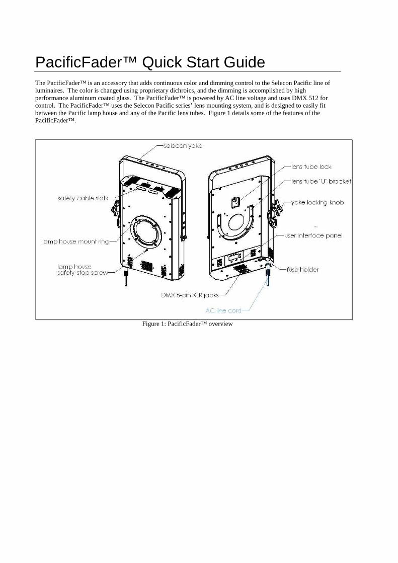
PacificFader™ Quick Start Guide The PacificFader™ is an accessory that adds continuous color and dimming control to the Selecon Pacific line of luminaires. The color is changed using proprietary dichroics, and the dimming is accomplished by high performance aluminum coated glass. The PacificFader™ is powered by AC line voltage and uses DMX 512 for control. The PacificFader™ uses the Selecon Pacific series’ lens mounting system, and is designed to easily fit between the Pacific lamp house and any of the Pacific lens tubes. Figure 1 details some of the features of the PacificFader™. Figure 1: PacificFader™ overview
Transcript of PacificFader™ Quick Start Guide - seleconlight.com · (Morpheus #27313), washers (Morpheus #...
PacificFader™ Quick Start Guide The PacificFader™ is an accessory that adds continuous color and dimming control to the Selecon Pacific line of luminaires. The color is changed using proprietary dichroics, and the dimming is accomplished by high performance aluminum coated glass. The PacificFader™ is powered by AC line voltage and uses DMX 512 for control. The PacificFader™ uses the Selecon Pacific series’ lens mounting system, and is designed to easily fit between the Pacific lamp house and any of the Pacific lens tubes. Figure 1 details some of the features of the PacificFader™.
Figure 1: PacificFader™ overview
Mounting
The PacificFader™ is designed to mount in a standard Selecon yoke (PDWRYOK001). This yoke attaches to threaded inserts built into the sides of the unit. The PacificFader™ ships with one yoke locking disc, and this locking disc can be re-mounted to either side of the unit depending on the desired position of the yoke locking clamp. Before mounting your PacificFader™ several things must be considered:
• Selecon Yoke • Location of the Yoke Locking Disc • Safety Attacment • Accommodating Large Lens Tube
Selecon Yoke
The PacificFader™ is designed to use a standard Selecon yoke (Selecon part number PDWRYOK001). The unit is shipped without a yoke and if a yoke is used, it must be mounted to the PacificFader™.
Mounting the Yoke:
1) Be sure the yoke locking disc is on the side best suited for your installation. (see “moving the yoke locking disc for more information.)
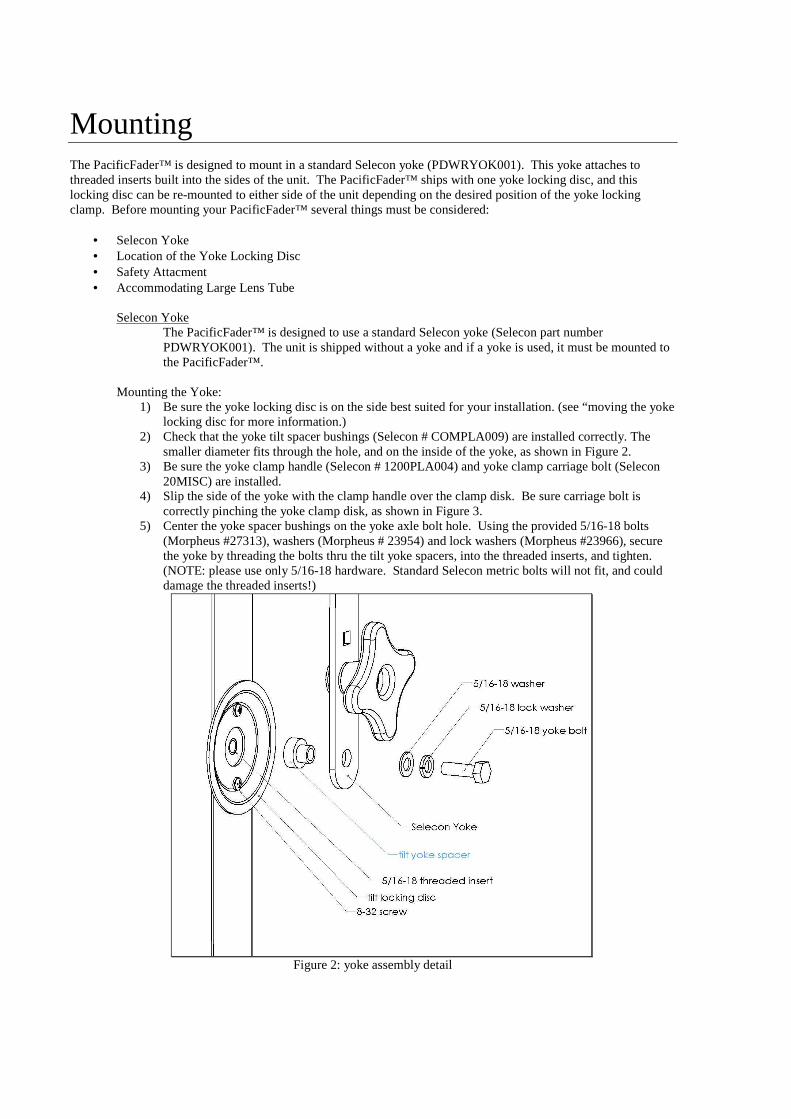
2) Check that the yoke tilt spacer bushings (Selecon # COMPLA009) are installed correctly. The smaller diameter fits through the hole, and on the inside of the yoke, as shown in Figure 2.
3) Be sure the yoke clamp handle (Selecon # 1200PLA004) and yoke clamp carriage bolt (Selecon 20MISC) are installed.
4) Slip the side of the yoke with the clamp handle over the clamp disk. Be sure carriage bolt is correctly pinching the yoke clamp disk, as shown in Figure 3.
5) Center the yoke spacer bushings on the yoke axle bolt hole. Using the provided 5/16-18 bolts (Morpheus #27313), washers (Morpheus # 23954) and lock washers (Morpheus #23966), secure the yoke by threading the bolts thru the tilt yoke spacers, into the threaded inserts, and tighten. (NOTE: please use only 5/16-18 hardware. Standard Selecon metric bolts will not fit, and could damage the threaded inserts!)
Figure 2: yoke assembly detail
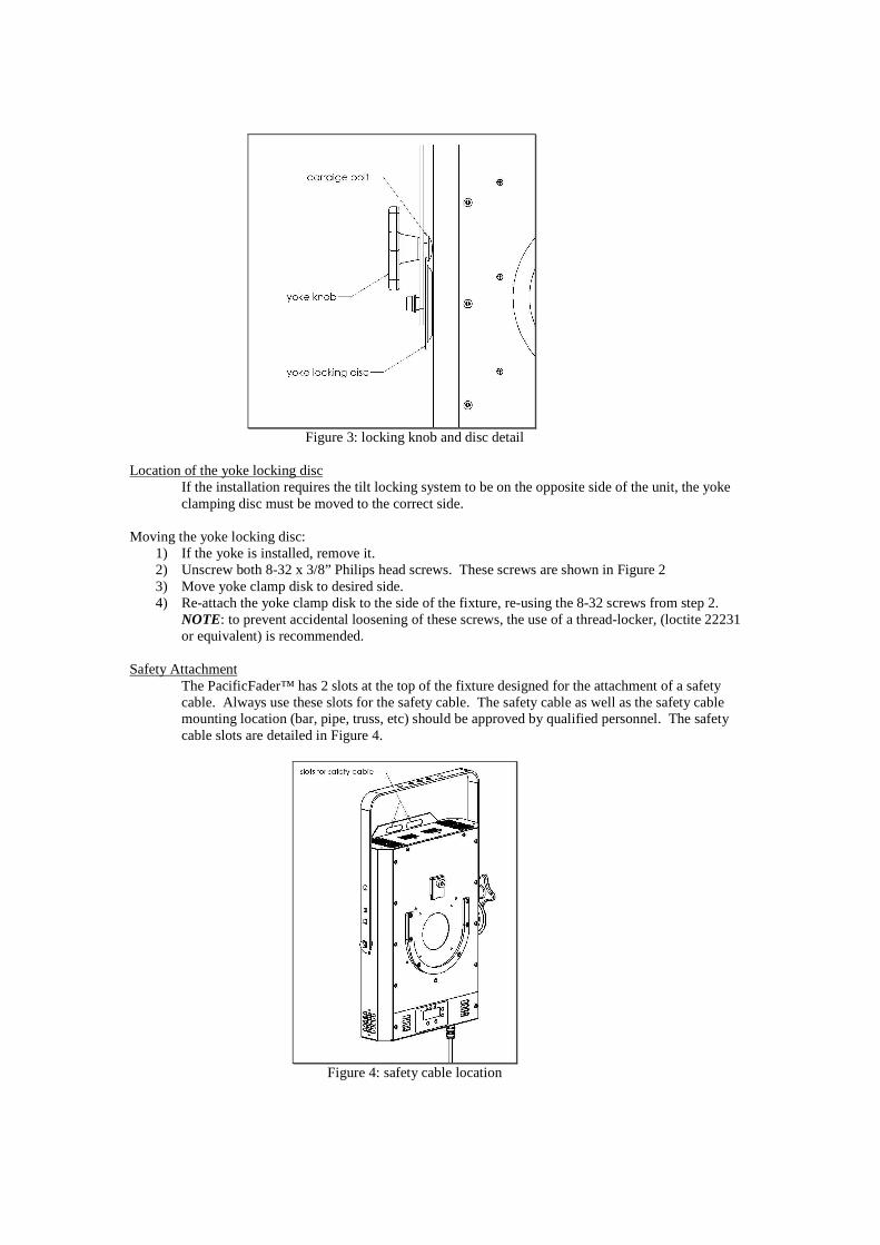
Figure 3: locking knob and disc detail
Location of the yoke locking disc
If the installation requires the tilt locking system to be on the opposite side of the unit, the yoke clamping disc must be moved to the correct side.
Moving the yoke locking disc:
1) If the yoke is installed, remove it. 2) Unscrew both 8-32 x 3/8” Philips head screws. These screws are shown in Figure 2 3) Move yoke clamp disk to desired side. 4) Re-attach the yoke clamp disk to the side of the fixture, re-using the 8-32 screws from step 2.
NOTE: to prevent accidental loosening of these screws, the use of a thread-locker, (loctite 22231 or equivalent) is recommended.
Safety Attachment
The PacificFader™ has 2 slots at the top of the fixture designed for the attachment of a safety cable. Always use these slots for the safety cable. The safety cable as well as the safety cable mounting location (bar, pipe, truss, etc) should be approved by qualified personnel. The safety cable slots are detailed in Figure 4.
Figure 4: safety cable location
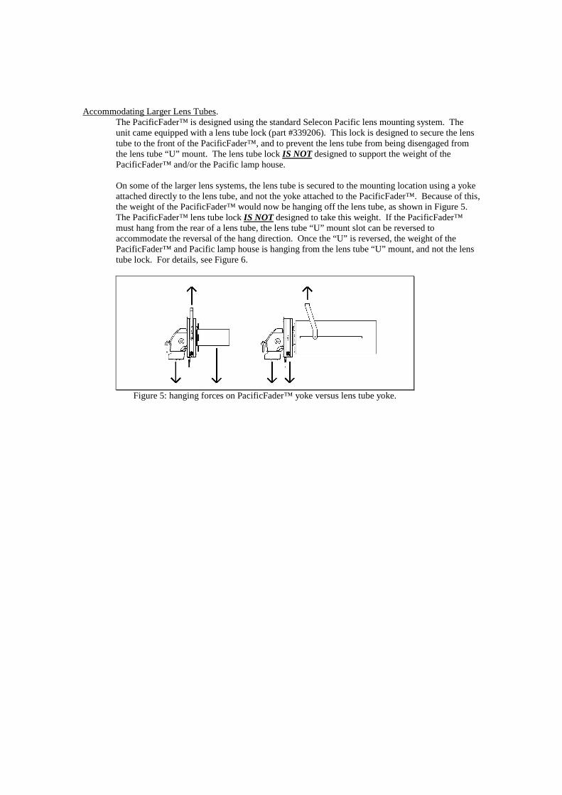
Accommodating Larger Lens Tubes. The PacificFader™ is designed using the standard Selecon Pacific lens mounting system. The unit came equipped with a lens tube lock (part #339206). This lock is designed to secure the lens tube to the front of the PacificFader™, and to prevent the lens tube from being disengaged from the lens tube “U” mount. The lens tube lock IS NOT designed to support the weight of the PacificFader™ and/or the Pacific lamp house. On some of the larger lens systems, the lens tube is secured to the mounting location using a yoke attached directly to the lens tube, and not the yoke attached to the PacificFader™. Because of this, the weight of the PacificFader™ would now be hanging off the lens tube, as shown in Figure 5. The PacificFader™ lens tube lock IS NOT designed to take this weight. If the PacificFader™ must hang from the rear of a lens tube, the lens tube “U” mount slot can be reversed to accommodate the reversal of the hang direction. Once the “U” is reversed, the weight of the PacificFader™ and Pacific lamp house is hanging from the lens tube “U” mount, and not the lens tube lock. For details, see Figure 6.
Figure 5: hanging forces on PacificFader™ yoke versus lens tube yoke.

Reversing the lens tube “U” mount: 1) Remove lens tube lock, if installed 2) Remove the six 8-32 flat head Philips screws 3) Rotate the lens tube “U” mount 180 degrees. 4) Centering the “U” on the aperture, align the six holes with the threaded inserts 5) Secure “U” slot using the six 8-32 flat head screws from step 2. NOTE: to prevent accidental
loosening of the screws, a thread-locker (loctite 22231, or equivalent) is recommended. 6) Re-install lens tube lock
Figure 6: lens tube “U” mount configuration.
Electrical Connections To operate the PacificFader™ two important electrical connections must be considered:
• AC Mains Power • DMX 512 low voltage control
AC Mains Power
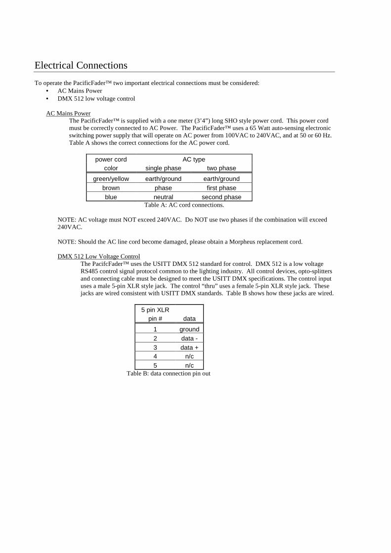
The PacificFader™ is supplied with a one meter (3’4”) long SHO style power cord. This power cord must be correctly connected to AC Power. The PacificFader™ uses a 65 Watt auto-sensing electronic switching power supply that will operate on AC power from 100VAC to 240VAC, and at 50 or 60 Hz. Table A shows the correct connections for the AC power cord.
power cord AC type color single phase two phase
green/yellow earth/ground earth/ground brown phase first phase blue neutral second phase
Table A: AC cord connections.
NOTE: AC voltage must NOT exceed 240VAC. Do NOT use two phases if the combination will exceed 240VAC. NOTE: Should the AC line cord become damaged, please obtain a Morpheus replacement cord.
DMX 512 Low Voltage Control
The PacifcFader™ uses the USITT DMX 512 standard for control. DMX 512 is a low voltage RS485 control signal protocol common to the lighting industry. All control devices, opto-splitters and connecting cable must be designed to meet the USITT DMX specifications. The control input uses a male 5-pin XLR style jack. The control “thru” uses a female 5-pin XLR style jack. These jacks are wired consistent with USITT DMX standards. Table B shows how these jacks are wired.
5 pin XLR pin # data
1 ground 2 data - 3 data + 4 n/c 5 n/c
Table B: data connection pin out
PacificFader™ User Interface
Set-up settings for the PacificFader™ are accessed via the user interface panel. These settings include: • 3 axes/4 axes/5 axes mode changes • DMX start address • LED display brightness
Setting the Number of Axes
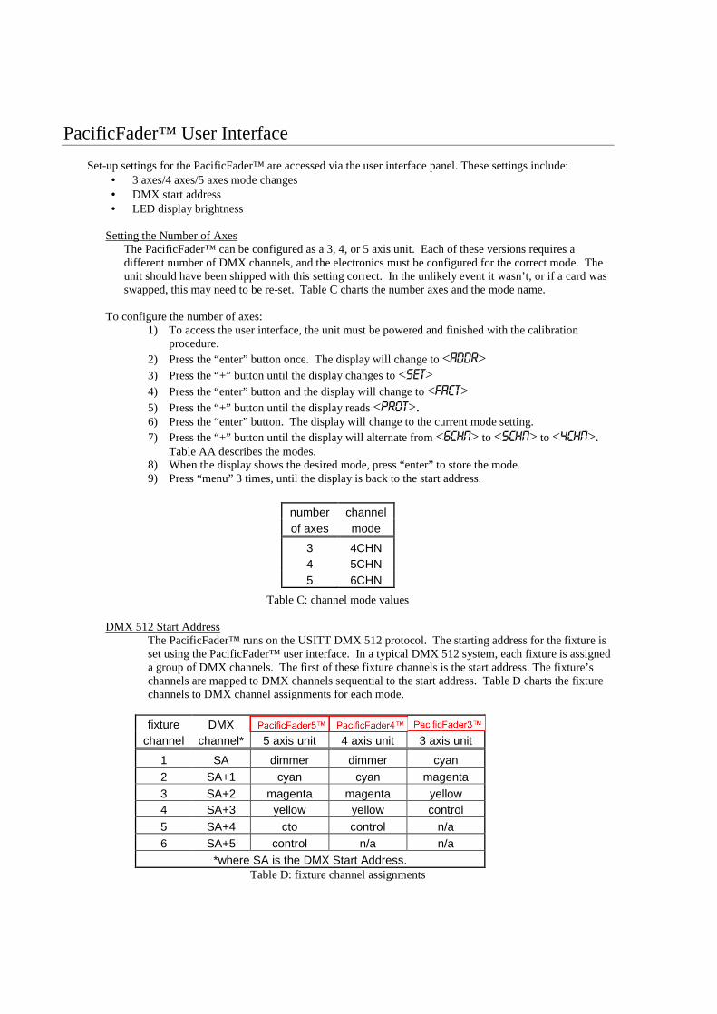
The PacificFader™ can be configured as a 3, 4, or 5 axis unit. Each of these versions requires a different number of DMX channels, and the electronics must be configured for the correct mode. The unit should have been shipped with this setting correct. In the unlikely event it wasn’t, or if a card was swapped, this may need to be re-set. Table C charts the number axes and the mode name.
To configure the number of axes:
1) To access the user interface, the unit must be powered and finished with the calibration procedure.
2) Press the “enter” button once. The display will change to <ADDR> 3) Press the “+” button until the display changes to <SET> 4) Press the “enter” button and the display will change to <FACT> 5) Press the “+” button until the display reads <PROT>. 6) Press the “enter” button. The display will change to the current mode setting. 7) Press the “+” button until the display will alternate from <6CHN> to <5CHN> to <4CHN>.
Table AA describes the modes. 8) When the display shows the desired mode, press “enter” to store the mode. 9) Press “menu” 3 times, until the display is back to the start address.
Table C: channel mode values DMX 512 Start Address
The PacificFader™ runs on the USITT DMX 512 protocol. The starting address for the fixture is set using the PacificFader™ user interface. In a typical DMX 512 system, each fixture is assigned a group of DMX channels. The first of these fixture channels is the start address. The fixture’s channels are mapped to DMX channels sequential to the start address. Table D charts the fixture channels to DMX channel assignments for each mode.
fixture DMX PacificFader PacificFader PacificFader channel channel* 5 axis unit 4 axis unit 3 axis unit
1 SA dimmer dimmer cyan 2 SA+1 cyan cyan magenta 3 SA+2 magenta magenta yellow 4 SA+3 yellow yellow control
5 SA+4 cto control n/a 6 SA+5 control n/a n/a
*where SA is the DMX Start Address. Table D: fixture channel assignments
number channel of axes mode
3 4CHN 4 5CHN 5 6CHN
Paul Weller
PacificFader3™
Paul Weller
PacificFader5™
Paul Weller
PacificFader4™
Setting the DMX 512 Start Address 1) To access the user interface, the unit must be powered and finished with the calibration
procedure. 2) Press the “enter” one time. <ADDR> should be displayed. 3) Press “enter” and the current start address should be displayed. 4) Press “+” or “-“ until the desired DMX start address is displayed. 5) Press “enter” to store the new DMX start address. 6) Press “menu” to get back to the default display. It is good practice to verify that the display
reads <CXXX> where XXX is the start address. Adjusting LED display brightness
The PacificFader™ user interface has a bright alpha-numeric style LED display. For some applications, it might be desirable to change the brightness of this LED display.
To adjust the brightness of the LED display:
1) To access the user interface, the unit be powered and finished with the calibration procedure. 2) Press “enter” one time. The display should read <ADDR> 3) Press “-“ one time. The display should read <SET> 4) Press “-” three times, or until the display reads <DISP> 5) Press “enter”. The display will show the current LED display brightness value, from <0000>
to <0005> to <OFF> 6) Press “+” or “-“ until desired brightness level is displayed. 7) Press “enter” to store desired brightness.
PacificFader™ operation Each axis in a PacificFader™ is assigned a fixture channel. Each fixture channel maps to a DMX channel based on the fixture start address. Varying the value of the DMX channel assigned to a color axis will cause that color to be mixed in the fixture’s beam. Varying the value of the DMX channel assigned to the dimmer (if equipped) will cause the fixture’s beam to vary in intensity. Setting the DMX value of the control in the range of a command function will cause that function to be executed.
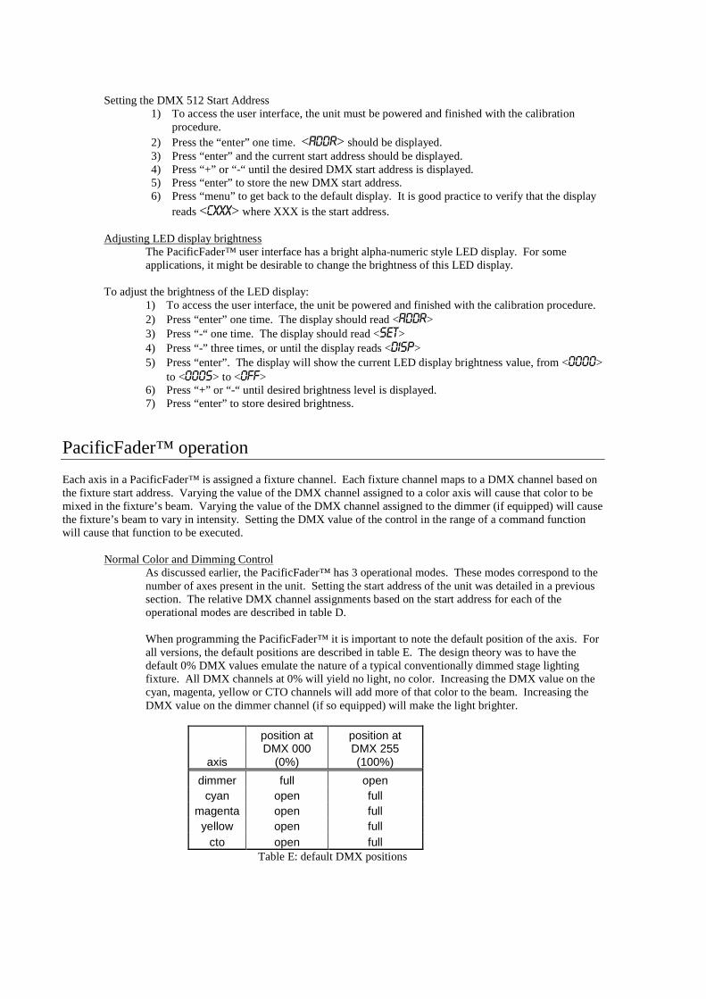
Normal Color and Dimming Control As discussed earlier, the PacificFader™ has 3 operational modes. These modes correspond to the number of axes present in the unit. Setting the start address of the unit was detailed in a previous section. The relative DMX channel assignments based on the start address for each of the operational modes are described in table D. When programming the PacificFader™ it is important to note the default position of the axis. For all versions, the default positions are described in table E. The design theory was to have the default 0% DMX values emulate the nature of a typical conventionally dimmed stage lighting fixture. All DMX channels at 0% will yield no light, no color. Increasing the DMX value on the cyan, magenta, yellow or CTO channels will add more of that color to the beam. Increasing the DMX value on the dimmer channel (if so equipped) will make the light brighter.
position at position at
axis DMX 000
(0%) DMX 255 (100%)
dimmer full open cyan open full
magenta open full yellow open full
cto open full Table E: default DMX positions
Control Channel Operation
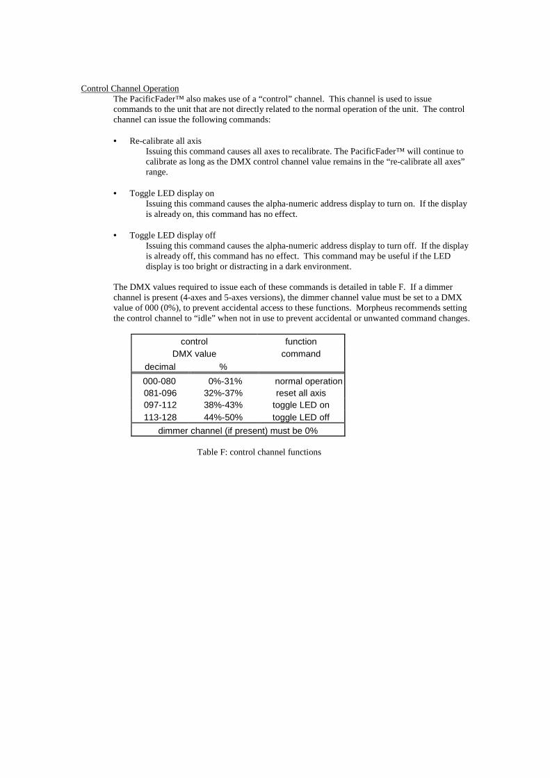
The PacificFader™ also makes use of a “control” channel. This channel is used to issue commands to the unit that are not directly related to the normal operation of the unit. The control channel can issue the following commands: • Re-calibrate all axis
Issuing this command causes all axes to recalibrate. The PacificFader™ will continue to calibrate as long as the DMX control channel value remains in the “re-calibrate all axes” range.
• Toggle LED display on
Issuing this command causes the alpha-numeric address display to turn on. If the display is already on, this command has no effect.
• Toggle LED display off
Issuing this command causes the alpha-numeric address display to turn off. If the display is already off, this command has no effect. This command may be useful if the LED display is too bright or distracting in a dark environment.
The DMX values required to issue each of these commands is detailed in table F. If a dimmer channel is present (4-axes and 5-axes versions), the dimmer channel value must be set to a DMX value of 000 (0%), to prevent accidental access to these functions. Morpheus recommends setting the control channel to “idle” when not in use to prevent accidental or unwanted command changes.
control function DMX value command
decimal %
000-080 0%-31% normal operation081-096 32%-37% reset all axis 097-112 38%-43% toggle LED on 113-128 44%-50% toggle LED off
dimmer channel (if present) must be 0%
Table F: control channel functions
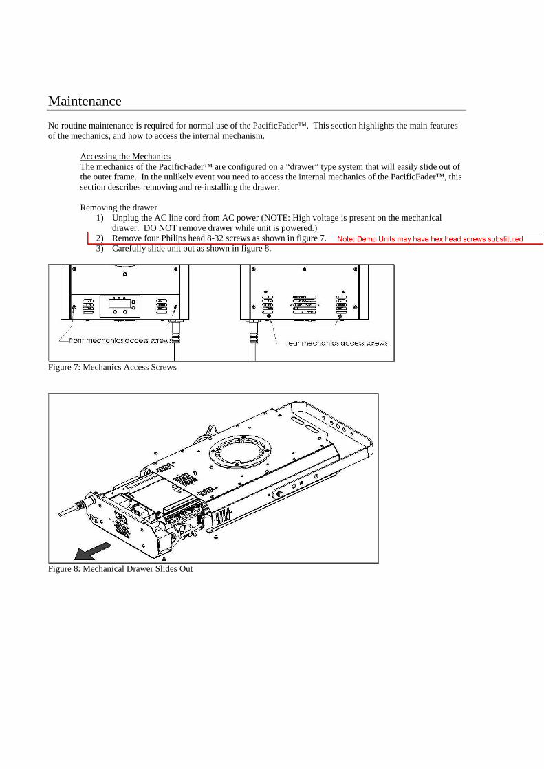
Maintenance No routine maintenance is required for normal use of the PacificFader™. This section highlights the main features of the mechanics, and how to access the internal mechanism.
Accessing the Mechanics The mechanics of the PacificFader™ are configured on a “drawer” type system that will easily slide out of the outer frame. In the unlikely event you need to access the internal mechanics of the PacificFader™, this section describes removing and re-installing the drawer.
Removing the drawer
1) Unplug the AC line cord from AC power (NOTE: High voltage is present on the mechanical drawer. DO NOT remove drawer while unit is powered.)
2) Remove four Philips head 8-32 screws as shown in figure 7. 3) Carefully slide unit out as shown in figure 8.
Figure 7: Mechanics Access Screws
Figure 8: Mechanical Drawer Slides Out
Paul Weller
Note: Demo Units may have hex head screws substituted
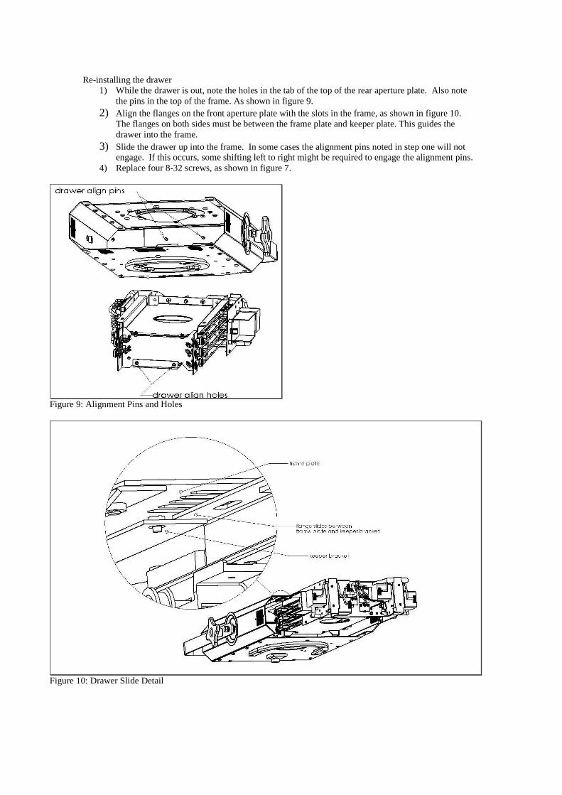
Re-installing the drawer 1) While the drawer is out, note the holes in the tab of the top of the rear aperture plate. Also note
the pins in the top of the frame. As shown in figure 9. 2) Align the flanges on the front aperture plate with the slots in the frame, as shown in figure 10.
The flanges on both sides must be between the frame plate and keeper plate. This guides the drawer into the frame.
3) Slide the drawer up into the frame. In some cases the alignment pins noted in step one will not engage. If this occurs, some shifting left to right might be required to engage the alignment pins.
4) Replace four 8-32 screws, as shown in figure 7.
Figure 9: Alignment Pins and Holes
Figure 10: Drawer Slide Detail
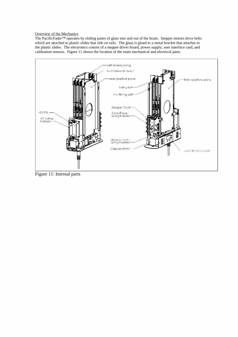
Overview of the Mechanics The PacificFader™ operates by sliding panes of glass into and out of the beam. Stepper motors drive belts which are attached to plastic slides that ride on rails. The glass is glued to a metal bracket that attaches to the plastic slides. The electronics consist of a stepper driver board, power supply, user interface card, and calibration sensors. Figure 11 shows the location of the main mechanical and electrical parts.
Figure 11: Internal parts