PACIFIC Rhino PFS 8 - Floor Cleaning Equipment · efficiency dust pickup the Pacific Rhino PFS 8...
20
Rhino PFS 8 8” Drum Sander (Expandable Drum) OWNERS MANUAL & OPERATING INSTRUCTIONS MAY 2010 REF. 179 PART # R000513 From Serial Number 05400 (110 Volt) PACIFIC PACIFIC
Transcript of PACIFIC Rhino PFS 8 - Floor Cleaning Equipment · efficiency dust pickup the Pacific Rhino PFS 8...

Rhino PFS 88” Drum Sander
(Expandable Drum)
OWNERS MANUAL & OPERATING INSTRUCTIONS
MAY 2010 REF. 179 PART # R000513
From Serial Number05400 (110 Volt)
PACIFIC
PACIFIC
NORTH AMERICAN SAFETY INSTRUCTIONS
USE AND APPLICATION
WARNING: This floor sanding machine must be grounded.
This floor-sanding machine shall be grounded while in use to protect the operator from electricshock. The machine is provided with a three-conductor cord and a moulded three-contactgrounding type attachment plug to fit the proper grounding type receptacle. The Green (orGreen and Yellow) conductor in the cord is the grounding wire. Never connect this wire to otherthan the grounding pin of the attachment plug.
This floor-sanding machine is provided with an attachment plug as shown in sketch A. It isintended for use on a nominal 120 volt circuit. If a properly grounded receptacle as shown insketch A is not available, an adaptor as shown in sketch 'C' should be installed as shown in sketchB if the outlet box that houses the receptacle is grounded. Be sure to fasten the grounding tab witha metal faceplate screw.
Floor sanding can result in an explosive mixture of fine dust and air. Use floor-sanding machineonly in a well-ventilated area free from any flame or match.
Moving Parts - to reduce the risk of injury, unplug the machine before replacing abrasive sheetsor carrying out any form of adjustment or servicing.
WARNING:
WARNING:
Risk of explosion.
Risk of potential injury.
This machine is intended for commercial use connected with the laying and maintaining of wooden floors anddecks.
These types of surfaces may be found both in commercial and household environments.
ATTACHMENT PLUG SKETCH ‘C’
METALSCREW
COVER OF GROUNDEDOUTLET BOX SKETCH ‘B’
ADAPTER
GROUNDINGMEANSCOVER OF GROUNDED
OUTLET BOX SKETCH ‘A’
GROUNDING PIN
Manufactured in UK © Hiretech
CONTENTS
WARNING
MAINS CABLE WIRING - PLUG
SPARE PARTS
SPECIFICATION
SAFETY
SET UP
PREPARATION
OPERATION
FLOOR SANDING TECHNIQUE
FLOOR TYPES
i
i
I
1
1,2
Assembly and Transport 2Installing Abrasive Belt 2
2
3,4
Drum Floor Sander 4Edger Sander 4Hand Sanding 4
Sanding Plank & Strip Floors 4Parquet & Block Floors 4
6
General 7Visual Inspection 7Drive Belts 7Dust Control System 7Lubrication 7Sanding Drum 7,8Care of Motor 8,9,10Electrical Testing 10
11
12,13
14, 15
16
16
FLOOR SANDER ABRASIVE GUIDE
SERVICE AND ROUTINE MAINTENANCE
TROUBLE SHOOTING
RHINO PFS 8 PARTS DRAWING
PARTS LIST
CIRCUIT DIAGRAM
FITTING A REPLACEMENT SWITCH
RHINO PFS 8
RHINO PFS 8
SERVICE & REPAIR 17
WARNING
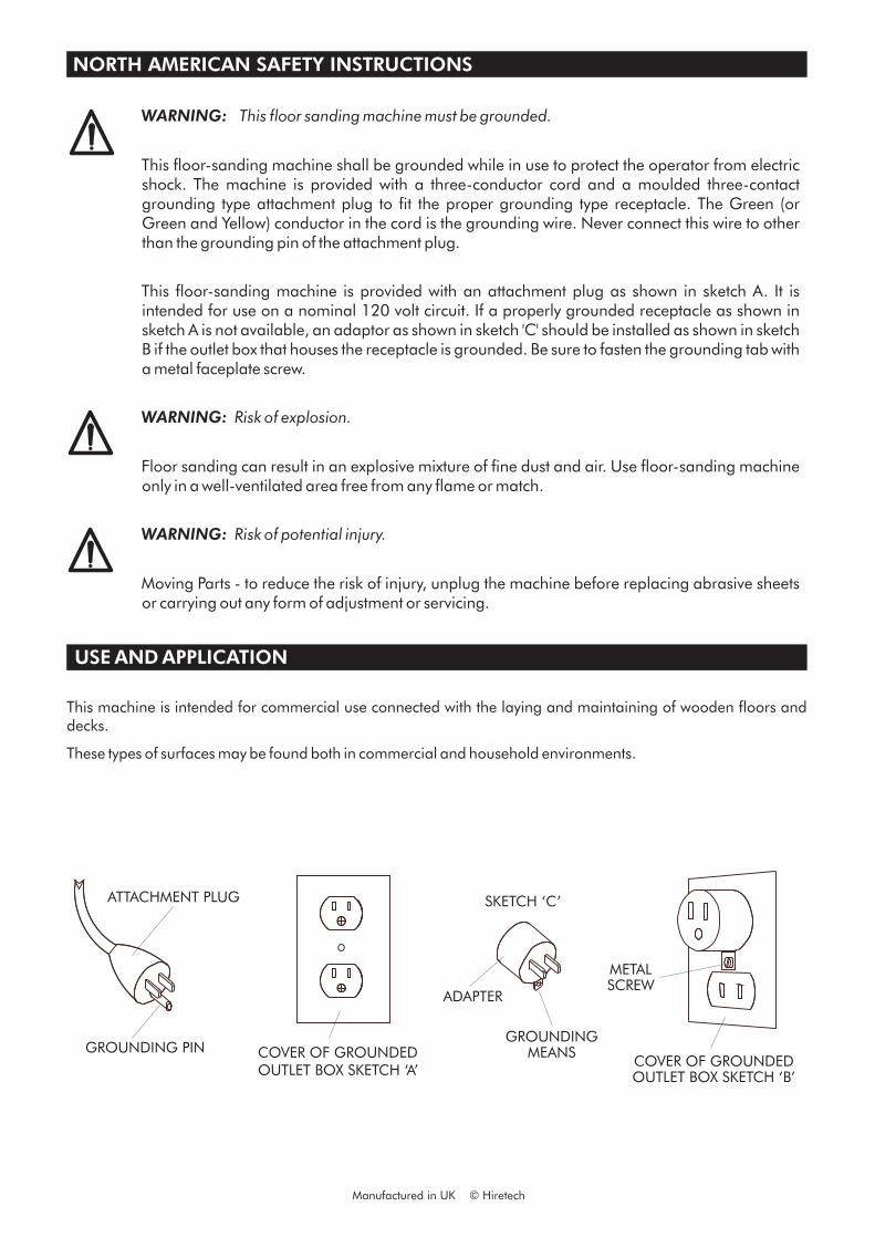
MAINS CABLE WIRING - PLUG
For safe operation of this machine, read and understand all instructions. Look for the ‘warning/caution’ symbol.
This symbol means that if you do not follow the instructions injury can occur to the operator anddamage to the machine and floor may result.
i
NORTH AMERICA
BLACK
WHITE
GREEN
BRASSTERMINAL
SILVERTERMINAL
SPARE PARTS
Use Pacific Floor Care genuine spare parts only for service and repair. Use of non-approved parts will void the productwarranty. See the back cover of this manual for the terms and conditions of the Pacific Floor Care Limited Warranty.
Pacific Floor Care reserves the right to make changes or improvements to it's products without prior notice.
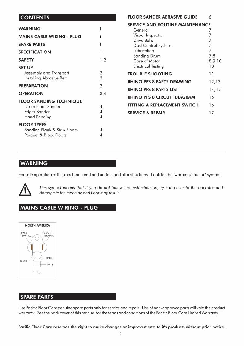
SPECIFICATION
The Pacific Rhino PFS 8 Drum Floor Sander will sandhard and soft wood floors, cork and compositionfloors that require rapid sanding and leveling to a finefinish. A powerful motor drives a finely balancedsanding drum covered in centrifugal drum rubberwhich grips a continuous abrasive belt providing ahigh quality finish to both hard and soft woods andother surfaces. Completely self contained with a highefficiency dust pickup the Pacific Rhino PFS 8 breaksdown into three simple component parts for easytransport. The Pacific Rhino PFS 8 is a highperformance floor sander suitable for professionaland homeowner use.
SAFETY
1. For safety it is recommended that a residualcurrent circuit breaker (ground fault interrupter)is used with this machine.
2. Check the operating voltage is correct and thatthe machine is switched OFF (‘O’) beforeconnecting to the power supply.
3. Always disconnect from the power supply whenchanging the abrasive belt, servicing the floorsander, replacing the dust bag or leaving themachine unattended.
4. Always replace the dust bag (paper type) orempty the dust bag (cloth type) when the dust inthe bag reaches the ‘MAX’ line or when themachine is left unattended.
5. Never dispose of or empty the contents of thedust bag into a fire or incinerator.
6. Never reuse the paper dust bag or use a nonstandard bag. Cloth bags must be in goodcondition with no holes.
7. Always wear a dust mask when using the floorsander, handling the dust bag or cleaning themachine after use.
11. Wear ear protection when using the floor sander.
12. Ensure adequate ventilation of the work area toavoid the formation of a combustible mixture offlying dust and air.
13. Never smoke when using or servicing the floorsander or when handling the dust bag.
8. Never leave the machine unattended with dust inthe dust bag. Dispose of all dust and dust bagsin a safe and proper manor. Dust left in a dustbag can be subject to spontaneous combustion.Damp down all disposable paper dust bags ondisposal.
9. Never operate the machine without the drumguard in place or if the drum guard is damaged.
10. The Pacific Rhino PFS 8 MUST be stored andtransport with a sanding belt in place at all timesto protect the drum rubber. If stored forprolonged periods of times support the PFS 8with the rubber wedge supplied in the OwnersPack. Place the wedge on the floor and roll theRhino PFS 8 onto the wedge in the centre of themachine until it comes to a stop to prevent thedrum rubber developing a flat spot.
store and transport with a sanding belt in place at alltimes to protect the drum rubber. If stored forprolonged periods of times support the PFS 8with the hardwood bar supplied in the OwnersPack. Place the bar under the Dust Shoe Ref. 72to raise the drum off the floor to prevent the drumrubber developing a flat spot.
1
Noise: 95 dBa at 1metre (3’ 3")
Vibration: 1.60 m/s² r.m.s.
Switch: Low voltage trip and overload protection.
Motor RPM: 8,500
Drum RPM: 3,300
Drive: Non-slip toothed timing belts and gear
cut pulleys.
Dust Pickup: Seated oversize vacuum fan with
adjustable dust pan, disposable paper
dust or cloth bag.
Moving Parts: Sealed for life ball bearings.
Guards: High impact injection moulded ABS.
Drum: 200mm 8(") wide dynamical balanced
high performance drum with expandable
drum rubber.
Abrasive: 200mm (8") x 493mm (19.5") resin
bonded belt, X-cloth backed wave joint
semi open 24grit to 150grit
Power Cable: 7m (23') Non-marking outer insulation.
Weight Net: 41.5kg (91.5lbs)
Shipping Weight: 50.0kg (110.3lbs)
Shipping
Dimensions:
78 x 40 x 44cm
(30.75" x 15.75" x 17.5")
Warranty: 2 years
110/120 V 50/60 Hz
220/240 V 50/60 Hz
110/120 V 8A
220/250 V 5A
Average
Load Current:
110/120 V 15A
220/250 V 8A
Power Supply:
Off Load
Current:
Continuous heavy duty AC/DC self
cooling 4 brush.
Motor:
Read the following Safety andOperational notes before using your
Floor Sander.Pacific Rhino PFS 8 Drum
14. Never expose the machine to rain or damp.Always store in a dry place.
15. Stop the floor sander immediately if damage tothe machine or abrasive belt is suspected.
16. Never allow the power cable to come into contactwith the sanding drum when the floor sander is inoperation. If the power cable becomes damagedand the inner conductors are exposed switch thepower OFF and remove the plug beforeattempting to move the machine. The cablemust be replaced by an authorized dealer orqualified electrician using Pacific Floor Caregenuine spare parts only.
14. Keep hands, feet and loose clothing away fromall moving parts of the machine.
17. Punch down or remove all nails, screws, tacksand other fixings from the floor before sanding toprevent contact with the sanding drum.
18. Never operate the machine without all theguards in place.
19. Keep children and pets clear at all times.
20. If the machine should fail to operate refer to theFault Finding Guide on page 10.
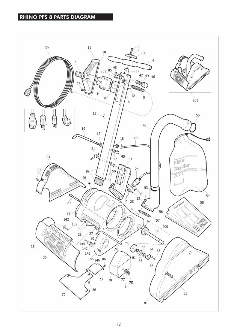
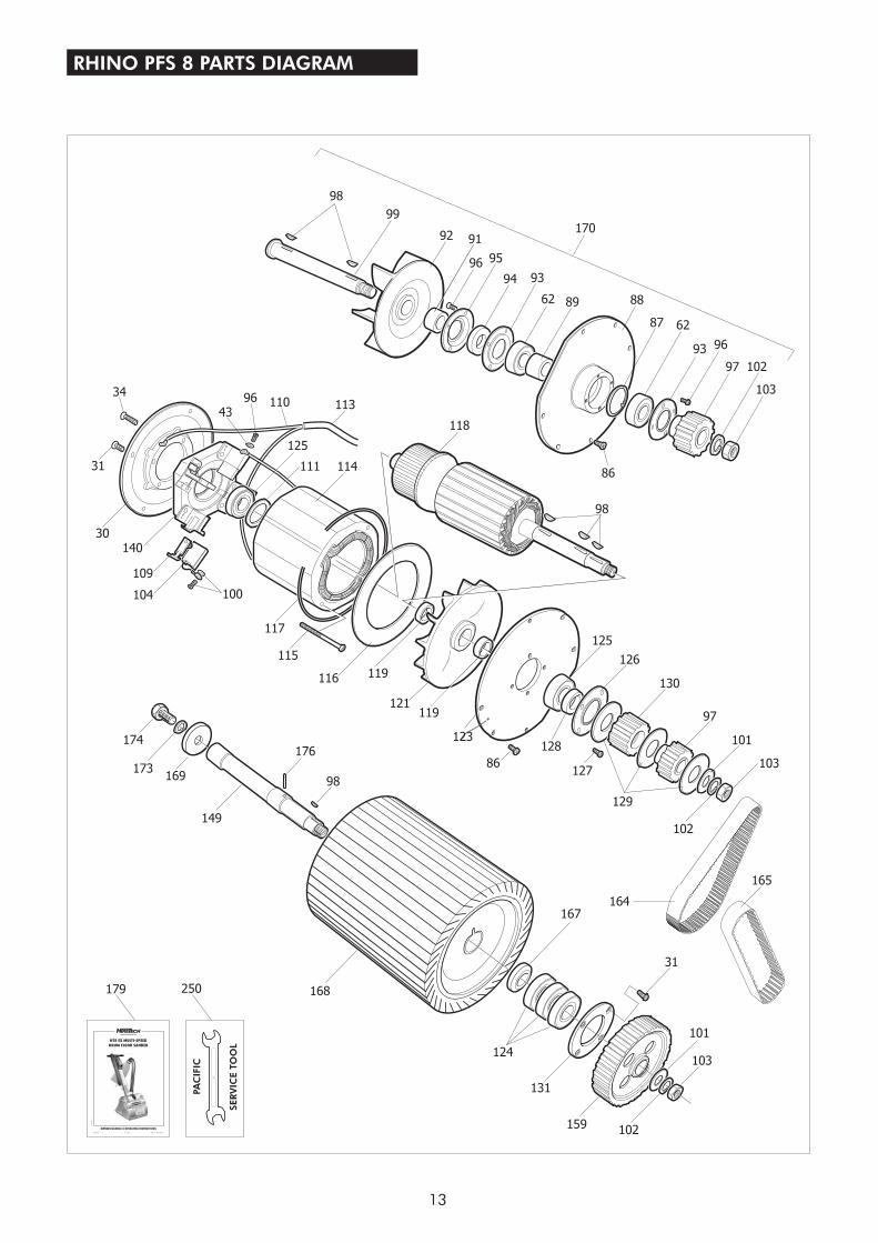
To help with the following instructions please refer tothe parts drawings on page 12 and 13
1. The breaks down into threecomponent parts, the main body, handleassembly and dust tube for easy handling andtransport. To assemble loosen the Clamp BracketRef.21 and slide the handle assembly into theHandle Bracket Ref.51. Adjust the height of thehandle so that your arms are slightly bent whenstanding upright behind the machine. This willprovide you with maximum control in operation.Tighten the clamp bracket firmly. Always ensurethat the clamp bracket is tight, check periodicallyduring use.
2. Connect the Cable Handle Ref.20 to the BodyTwist Lock Ref.24 at the rear right hand side of thefloor sander body. Align the plug with the pins,push in and twist clockwise to lock.
3. Slide the Exhaust Tube Ref.59 into the ExhaustBracket Ref.56 and push fully home.
4. Fit a paper dust bag following the instructionsprinted on the bag. If a cloth bag is used ensurethat it is tied securely around the dust tube neckand that the bag is in good condition with noholes.
5. To prepare the floor sander for use place the
Assembly and Transport
Pacific Rhino PFS 8
SET UP
machine on the floor and remove the main cablefrom it's storage position on the handle assembly.Check that the cable is in good condition andthat all fittings are secure.
6. To dismantle the floor sander reverse procedure1 to 5 above.
7. Always ensure that the floor sander is secure andcannot move when being transported in avehicle. The floor sander is heavy. Take carewhen lifting and carrying the machine.
1. Ensure the power cable is disconnected from thepower supply.
6. Lower the drum guard and stand the machine up.The floor sander is now ready for use.
Note: Use Pacific Floor Care genuine floor sanderabrasives for the best sanding performance andfinish. They will also reduce the risk of tearing due topoor fit which is a common problem with generic andnon standard abrasives.
1. Where possible remove all furniture from thearea or room. TheFloor Sander features an efficient dust pickup,however, some dust will escape.
2. Remove all tacks, staples and other unwantedfixings from the floor. Failure to do so will result
Installing Abrasive Belt
2. Tip the floor sander back so that it rests on therubber buffer on the rear of the handle.
3. Lift the Drum Guard Ref.35 to expose thesanding drum.
4. Select a suitable grade of abrasive belt (seeAbrasive Paper Guide on page 7). Checkdirection arrows printed on inside of the abrasivebelt. The arrows must point clockwise in the samedirection as the drum rotates. Look at the arrowon the side of the drum guard for reference.
5. Ware gloves when fitting the abrasive belt.Kneeling on the left hand side of the machineplace one end of the abrasive belt on to thesanding drum at a slight angle then gently rotateclockwise to locate the end of the belt fully on tothe sanding drum.
Now slide the belt fully onto the sanding drumwhile gently rotating in a clockwise direction.
Ensure the sanding belt is centred on the sandingdrum
Take care not to trap fingers around the mainframe and dust shoe.
Pacific Rhino PFS 8 Drum
PREPARATION
2
in damage to the abrasive paper and sandingdrum.
3. Punch all nails below the surface of the floorusing a suitable nail punch and hammer. Anyscrews used to fix boards should be counter sunkbelow the surface. During sanding any nails orscrews that become exposed must be punched orcounter sunk further.
4. Firmly fix all loose boards or blocks.
5. Remove heavy wax, grease and dirt deposits byhand.
6. Sweep and vacuum the floor thoroughly toremove dirt and discarded fixings.
7. Ensure good ventilation by opening windows.
1. Move the floor sander to the location of yourwork.
2. Connect the power cable to a suitable powersupply ideally located behind or to one side ofthe machine and work area.
3. Wear a dust mask and ear protection.
4. Hold both handles with the main cable held in asmall loop in the left hand and then passed overthe left shoulder.
5. Apply light downwards pressure on the handlesto tip the floor sander back to raise the sandingdrum off the floor. Switch on by pushing theON/OFF switch to the ‘I’ position.
6. Now move the floor sander slowly forward andat the same time release the pressure on thehandles to gently lower it so that the sandingdrum comes into contact with the floor.
7. Guide the floor sander in a straight line at a slowwalking pace. Do not force or hold the floorsander back. Allow the machine to do the workand always move at an even pace.
8. At the end of the pass while still moving forwardtilt the floor sander back so that the sandingdrum comes clear of the floor. Now movingbackwards lower the floor sander again and pullit backwards over the area just sanded moving ata steadily even pace. Take care to ensure thatthe power cable is kept clear of the sanding drum
CAUTION - theFloor Sander is a powerful machine.Always ensure that you have a firm gripbefore switching on.
Pacific Rhino PFS 8 Drum
OPERATION
3
at all times. At the end of the sanding pass andwhile still moving backwards tilt the floor sanderback so once again the sanding drum comesclear of the floor.
Move the machine over so that it overlaps thearea just sanded by 3" (75mm) and start to sandthe next pass repeating the above technique.
i. Always ensure that the floor sander ismoving when in operation and thesanding drum is in contact with the floor.
ii. Never lift the back of the machine whensanding.
iii. Never apply pressure to try to increase therate of sanding. Damage to the floor andmachine will occur.
iv. Never bounce or drop the floor sander onto the floor. Always lower the machinegently.
v. Never dwell in one place, move steadily atall times.
vi. Never allow the power cable to come intocontact with the sanding drum.
9. When the dust in the dust bag reaches the ‘MAX’line stop sanding. Disconnect the power cablefrom the power supply and remove the paperdust bag. Turn the top of the paper dust bag overto stop the escape of dust and dispose of into asuitable container.
Never reusethe paper dust bag or empty it or dispose of it intoa fire. If a cloth bag is used empty into a suitablecontainer being careful to contain the dust. Donot dispose of the contents into a fire.
10. Fit a new paper dust bag or refit the cloth bag.Reconnect the floor sander to the power supplyand continue sanding.
11. When taking a break from work disconnect thepower cable from the supply, remove anddispose of the paper dust bag, or empty the clothbag as detailed in 9. above. Never leave thefloor sander unattended with the dust bag inplace containing dust.
12. On completion disconnect the power cable fromthe supply. Remove and dispose of the paperdust bag, or empty the cloth bag as detailed in 9.above. Stow the cable on the handle assemblyand if required dismantle for transportation.
CAUTION - to prevent damage to thefloor surface, work piece or machinefollow these rules.
Dampen the dust bag downwith water to reduce the risk of fire.
Carry out maintenance as recommended inMaintenance and Servicing.
DANGER - never leave the floor sanderunattended with dust in the dust bag.Always remove the dust bag and disposeof into a suitable container.
Pacific Rhino PFS 8 Drum Sander
Pacific Wolverine Edger Sander
Hand Sanding
- a powerful floorsander designed for the rapid leveling and sanding ofall types of wood flooring excluding thin laminated orveneered floors. Load the sander with abrasivemaking sure that it is skin tight around the drum.Loose sheets will tear. Place the sander on the righthand wall (unless you are making an angled cut onuneven floors) with about two thirds of the floor infront of you. Start the sander with the drum off thefloor then walk forward at an even pace and ease thedrum on to the floor. As you near the end of the pass,gradually raise the drum off the floor. Practice thistechnique before turning on the sander.
Cover the same path you made on the forward cut bypulling the machine backwards and easing the drumto the floor as you begin the backward pass until youreach the original starting point, then ease the drumoff the floor.
When two thirds of the floor is sanded, turn the floorsander around and sand the remaining third in thesame way. Overlap the one third area by 2 to 3 feetwith the two thirds area to blend the two areastogether.
- a powerful edgersander designed for sanding along the edges of afloor without damaging the baseboards or moldings.Also suitable for smaller areas where the Pacific RhinoPFS 8 Drum Sander will not reach like stair treads andclosets. Load the abrasive disc making sure theretaining bolt is tight. Start the edger with the disc offthe floor then lower the disc to the floor as you movethe sander. Work progressively moving the sander ina sweeping motion from side to side.
- to sand difficult to reach areasscrape and sand the floor by hand. Use a scraper toremove old finishes, always scraping in the directionof the grain, and then sand by hand using the samegrit abrasive as you finished with when machinesanding. See Floor Sanding Technique diagrams onpage 5.
WARNING - never bounce the sandingdrum or dwell in one place as this willsand dips and hollows in the floor.
FLOOR SANDING TECHNIQUE
FLOOR TYPES
PLANK & STRIP FLOORS
PARQUET & BLOCK FLOORS
Old floors in good condition
Uneven floors
Floors with an existing finish
- when the floor is ingood condition - no uneven edges, cupping orcrowning of planks and strips - and you want to re-surface the floor, sanding back to new wood, startsanding in the direction of the planks or strips - withthe wood grain. Start with a grit abrasive.Complete the first cut with the Pacific Rhino PFS 8Drum Sander then sand up to the baseboards anddoor thresholds with the Pacific Wolverine Edger,using a grit abrasive, blending the edges inwith the main floor area. Sweep the floor. Using a
grit abrasive, sand the main floor areawith the drum sander and then complete the floor withthe edger using a grit abrasive. Sweep the floor.Finish sanding the main floor area with the drum floorsander using a grit abrasive.
- when the floor is uneven sand
diagonally at 45 across the room in both directionsusing the Pacific Rhino PFS 8 Drum Sander with acoarse grit abrasive. Only make one cut on bothdiagonals, this will achieve a basic level. Nowcomplete the floor as for a level strip or plank floor.Use the same grit abrasive as was used on the 45 cutfor the first cut parallel to the planks or strips.
- when re-finishing afloor remove as little of the existing surface aspossible. If the floor is badly marked and scratchedand has to be sanded back to new wood use thePacific Rhino PFS 8 Drum Sander and PacificWolverine Edger Sander. Always try a medium gritpaper first, particularly on a diagonal cut. If 90% ofthe old finish is removed and the floor is generallyleveled, you do not need to use a coarse grit abrasive.
The grain of the wood will run in a number ofdirections so sand the floor in the direction of themain source of natural light in the room. If there is nosource of natural light sand in the direction of thelongest side of the room or, if the room is square, inthe direction the furniture is laid out and how peoplenormally use and view the room.
This technique will help mask any imperfections in thefloor. Complete the sanding operation as detailedfor plank or strip floors.
medium
medium
fine
fine
medium/fine
o
o
4
5
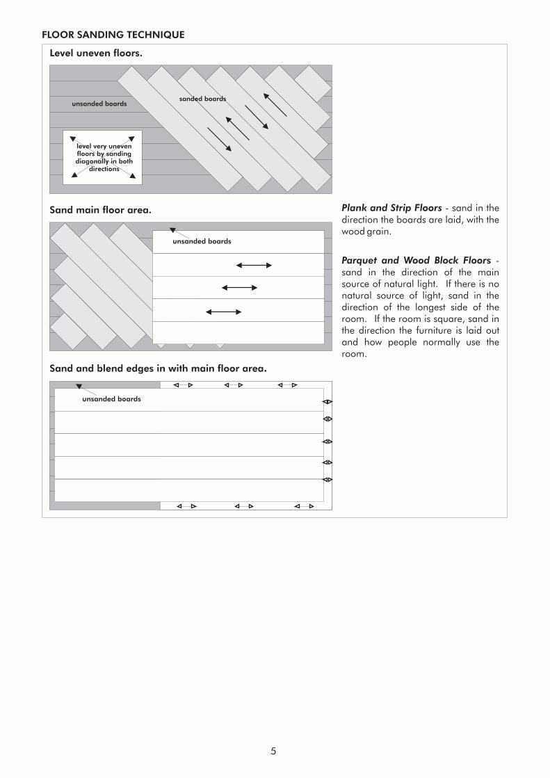
unsanded boardssanded boards
level very unevenfloors by sandingdiagonally in both
directions
unsanded boards
unsanded boards
Level uneven floors.
Sand main floor area.
Sand and blend edges in with main floor area.
FLOOR SANDING TECHNIQUE
Plank and Strip Floors
Parquet and Wood Block Floor
- sand in thedirection the boards are laid, with thewood grain.
-sand in the direction of the mainsource of natural light. If there is nonatural source of light, sand in thedirection of the longest side of theroom. If the room is square, sand inthe direction the furniture is laid outand how people normally use theroom.
s
6
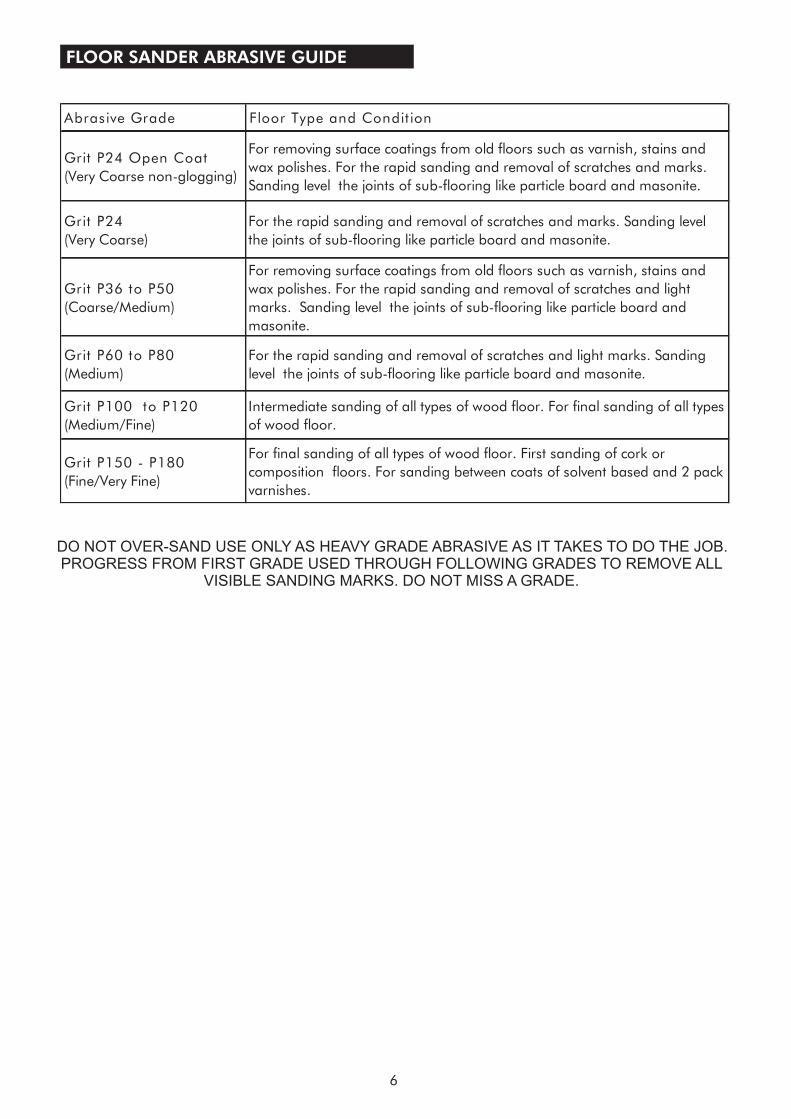
FLOOR SANDER ABRASIVE GUIDE
DO NOT OVER-SAND USE ONLY AS HEAVY GRADE ABRASIVE AS IT TAKES TO DO THE JOB.PROGRESS FROM FIRST GRADE USED THROUGH FOLLOWING GRADES TO REMOVE ALL
VISIBLE SANDING MARKS. DO NOT MISS A GRADE.
Abrasive Grade Floor Type and Condit ion
Grit P24 Open Coat
(Very Coarse non-glogging)
For removing surface coatings from old floors such as varnish, stains and
wax polishes. For the rapid sanding and removal of scratches and marks.
Sanding level the joints of sub-flooring like particle board and masonite.
Grit P24
(Very Coarse)
For the rapid sanding and removal of scratches and marks. Sanding level
the joints of sub-flooring like particle board and masonite.
Grit P36 to P50
(Coarse/Medium)
For removing surface coatings from old floors such as varnish, stains and
wax polishes. For the rapid sanding and removal of scratches and light
marks. Sanding level the joints of sub-flooring like particle board and
masonite.
Grit P60 to P80
(Medium)
For the rapid sanding and removal of scratches and light marks. Sanding
level the joints of sub-flooring like particle board and masonite.
Grit P100 to P120
(Medium/Fine)
Intermediate sanding of all types of wood floor. For final sanding of all types
of wood floor.
Grit P150 - P180
(Fine/Very Fine)
For final sanding of all types of wood floor. First sanding of cork or
composition floors. For sanding between coats of solvent based and 2 pack
varnishes.
SERVICE & ROUTINE MAINTENANCE
CAUTION - maintenance and repairsmust be carried out by authorizedpersonnel only. To prevent injury, alwaysremove the power cable from the powersupply before undertaking any work onthe machine. Do not operate the floorsander unless it is fully assembled and allguards are in place. Use Pacific FloorCare genuine spare parts only.
General
Visual Inspection
1. Always make a list when first examining themachine, to remind you of parts or actionneeded on completion of repair/service.
2. The Pacific Rhino PFS 8 Drum Sander is subject tohigh speeds. All screws should be fitted using asuitable thread lock compound.
3. On completion of any work or service on anelectrical tool or appliance statutory safety testsmust be carried out by a competent person andrecorded (see Testing for Electrical Safety page 8).
4. The needs nolubrication during routine servicing.
5. Always ensure that the electrical supply isdisconnected before starting any routineservicing or repair.
1. Check that the drum guard Ref.35 is in goodcondition and functioning correctly. Ensure thatthe Warning Label Ref.36 is present and legible.
2. Check all other guards and mechanical parts arein good condition.
3. Examine the power cable Ref.39 and the handlecable Ref.20. If the outer insulation shows theslightest of abrasions or the inner conductors areexposed, then the cable must be replaced. Thecable must not be repaired with tape orinsulation sleeve
4. Examine both the mains plug and theinterconnecting socket, Body Twist Lock Ref.24.The plugs must be opened and examined (seeElectrical Testing page 8).
5. If a cloth type bag is in service check the condition,old clogged cloth dust bags make for aninefficient dust pickup.
6. Ensure that all labels are present and in goodcondition.
Pacific Rhino PFS 8 Drum Sander
Drive Belts
Dust Control System
Lubrication
1. To examine the condition of the Drive BeltsRef.164 and Ref.165 remove the four screwsRef.83 and the Belt Guard Ref.81.
2. Lift the Fan Belt Ref.165 while rotating the pulleyremove the fan belt. Repeat for the Drum BeltRef.164.
3. Examine the pulleys for wear, worn or damagedpulleys should be replaced
4. To reduce the instance of belt breakage, examinethe drive belts, look for cracks or fraying andreplace if necessary with new belts. To replacereverse the above procedure taking care to avoidbending the belts tighter than the pulley diameteras this can result in damaged belts. Refit the beltguard.
1. For efficient dust pick up ensure that cloth typedust bags are clean and unclogged and that theintake is clear and properly adjusted.
2. Turn the machine on to its side and loosen thethree Screws Ref.71 and remove the Dust ShoeRef.72 and clear any obstruction. The grit fromthe abrasive paper can wear away the leadingedge of the dust shoe, if this has occurred thenfile or grind the leading edge level beforerefitting.
Install the dust shoe ensuring that the clearancebetween the shoe and the drum is maintained at3/8“ (10mm).
1. The iscompletely lubricated. The bearings are sealedand do not require lubrication. In the unlikelyevent that a bearing requires replacement use aPacific Floor Care genuine spare part only as thegrease contained in these bearings is special. Astandard bearing is not suitable and may resultin further damage.
CAUTION - take care to avoid trappingyour fingers when removing or replacingthe drive belts.
Pacific Rhino PFS 8 Drum Sander
In operation the sanding belt is held in place on thesanding drum by centrifugal force. It is very importantthat the drum rubber and abrasive guides aremaintained in good condition at all times.
The Pacific Rhino PFS 8 MUST be stored and transportwith a sanding belt in place at all times to protect thedrum rubber. If stored for prolonged periods of times
Sanding Drum.
7
support the PFS 8 with the rubber wedge supplied inthe Owners Pack. Place the wedge on the floor androll the Rhino PFS 8 onto the wedge in the centre of themachine until it comes to a stop to prevent the drumrubber developing a flat spot.
1. Check that power supply is disconnected. Tilt themachine back and rest the handle on the floor.Open the drum guard and remove the abrasivebelt if fitted. Inspect the condition of the drumrubber. A damaged or worn drum rubber mustbe replaced to maintain machine performance.A damaged or worn drum rubber can result inpoor sanding performance with subsequentdamage to the floor surface and can bedangerous in operation.
If the machine moves from side to side whensanding or you are experiencing inconsistentsanding performance this can indicate a worn ordamaged drum rubber. This is caused becausethe drum rubber is not gripping the sanding belt.
2. To replace the drum rubber contact your localService Agent. Pacific Floor Care operate asimple exchange program to replace Rhino PFS8 Sanding Drums. Please contact your localservice agent for information, service levels andpricing.
3. Check the condition of the Abrasive Guides(Ref.142). It is very important that the AbrasiveGuides are maintained in good condition. TheAbrasive Guides ensure that the abrasive beltruns evenly and centred on the sanding drum.Worn Abrasive Guides will cause wear to thedrum rubber, result in poor sandingperformance and cause damage to the machineand floor surface. Worn guides will alsodamage the abrasive belt and may cause it totear.
The Abrasive Guides should not be worn by morethan 1/8” (3mm). The thickness from new is 1/4”(7mm).
4. When fitting new Abrasives Guides or whenreplacing the Drum Guard (Ref. 35) ensure thatthe correct gap is maintained between the edgeof th sanding drum and the Abrasive Guides .
Remove abrasive belt if fitted, using the SpacerGuide Abrasive (Ref.143) adjust the gapbetween the Abrasive Guide and the edge of thesanding drum on both sides of the drum asfollows;
8in wide abrasive - gap 3/32 to 5/32in
200mm wide abrasive - gap 1.5 to 2.5mm
The Spacer Abrasive Guide are of variousthicknesses. User the thicker guides first andadjust the gap using the thinner spacers if
required.
5. Check the condition of the rear wheels (RollersRef.61). The wheels must be free from dirt androtate freely. Check the condition of the ShaftRoller Ref.60, use a straight edge to make surethe shaft is not bent.
1. The motor must be kept free from grease anddust. DO NOT use high pressure air to blow themotor clean. Use a vacuum and soft brush toclean the motor and brush block assembly.
2. The motor brushes must be checked regularly,inspect the brushes every three months or every300 hours from new and then every 100 hours ofuse thereafter.
3. Replace ALL FOUR motor brushes when any onebrush has worn to 1/2” or less in length. BrushesMUST slide freely in the brush holders.
When any one motor brush is worn down to theware indicator inspect the brushes ever 100hrs.Replace all four motor brushes when any ONE(1) motor brush is worn down to the minimumbrush length as indicated by the bottom of thetriangle stamped on the motor brush.
4. To inspect and replace motor Brushes Ref.104,with the brush block assembly removed.
i. Remove the three Screws Ref.82 andremove the Wall End Guard Ref.84 toexpose the motor brush assembly.
ii. Remove the four retaining Screws Ref.31from the Shield Wall End Ref.30, insert twoof the screws into the ‘jacking holes’situated adjacent to the countersunkretaining holes.
iii. Carefully tighten these screws until theshield wall end is jacked clear of the outercasting. Withdraw the shield-wall end.
iv. With the brush block assembly completeand the connecting leads still attached.You will note that as the brush blockassembly is withdrawn the brushes springtowards the center and often the brushsprings fall clear as the brushes are nolonger at a height to retain them. Take carenot to lose any springs.
v. To remove a brush spring with a brush inthe operating position push the brushspring down and towards the brush and liftout.
vi. Using a cross recess screwdriver removethe four brush shunt (pigtail) retainingScrews Ref.105 and lock Washers Ref.100.
Care of Motor
8
vii. Remove the four brushes. Remove the two‘jacking’ screws.
viii. Thoroughly clean the brush assembly andhousing using a soft brush and a suitablevacuum cleaner.
ix. Inspect the four brushes for damage orwear and if any one brush is found to bedamaged or worn to a length of 5/8“(16mm) or less in length then replace allfour brushes.
x. When replacing brushes ensure freemovement in each brush holder and fit thebrush with the shunt (pigtail) towards thefield coil. Ensure that each brush shunt isconnected securely with the screw, andlock washer, two spare screws and lockwashers are provided with each pack ofbrushes. Do not fit the brush springs at thisstage.
xi. Pull each brush up to the top of the holderusing the shunt wire to retain it in thisposition for the next stage.
xii. Enter the assembly into the main frametaking care to avoid contact between thebrushes and the commutator of thearmature, that the shield wall end iscorrectly aligned with the main frame andthat no leads are trapped. There is adepressed pattern on the shield wall endand on the main frame to assist alignment.Both the bearing fit and the main frame fit
are ‘light contact’ and may require lightlytapping into position using a soft mallet.DO NOT FORCE.
xiii. Replace and tighten the four countersunkScrews Ref.31.
xiv. Remove the four brush block retainingScrews Ref.31 and the single timing ScrewRef.34 from the Shield-Wall End Ref.30.The brush block assembly is now free torotate. To fit the brush springs rotate thebrush block assembly counter clockwise(over towards the rear of the machine) untilthe lower brush holder is accessible, fit thebrush spring by inserting into the holderwith the coil spring over the brush thenpush down until the tag comes into contactwith the holder, slide the tag away from thebrush and release. The brush spring willclip into position. Check the spring andbrush for correct alignment and freemovement.
xv. Rotate the brush block assembly clockwiseand repeat to fit the remaining threesprings. The switch and field cablesrestrict the movement of the brush blockassembly, take care not to loosen ordamage these cables.
xvi. Return the brush block assembly to itsoriginal position and align the timingnotch in the block with the timing hole,screw the timing Screw Ref.34 into position.
9
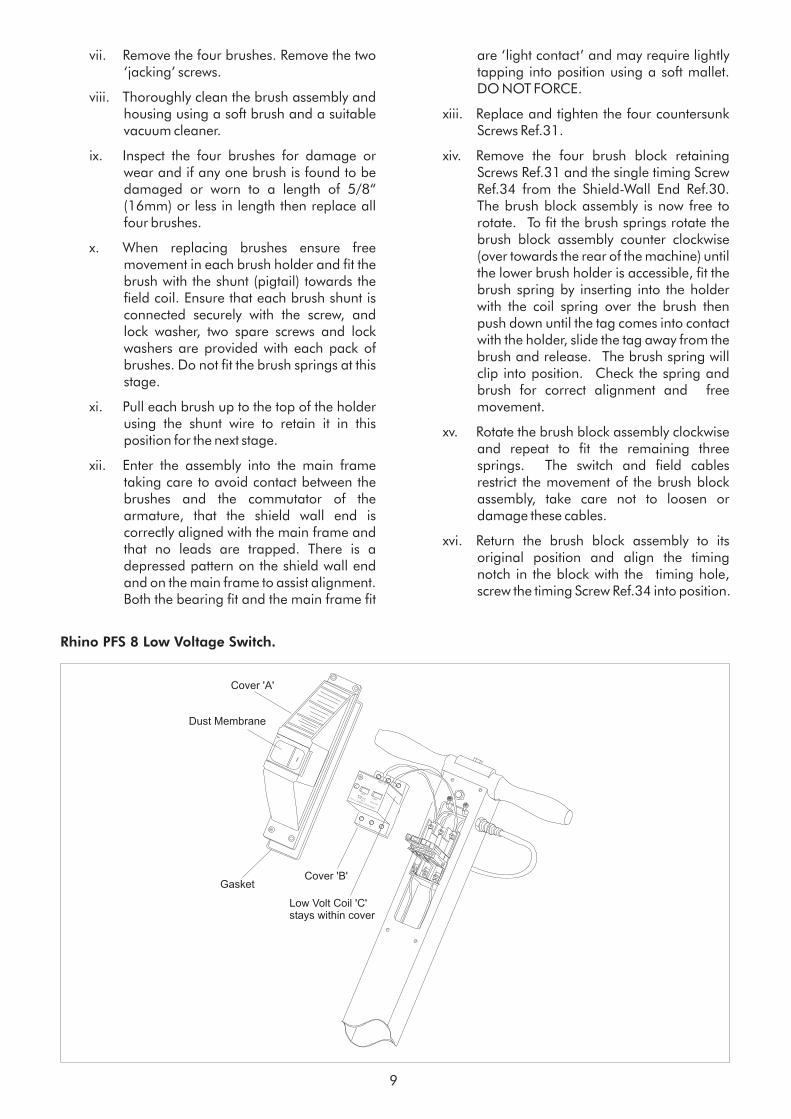
Rhino PFS 8 Low Voltage Switch.
CE 0 U AC690V CSN EN 60947
START
STOP
6
4
2
?? ??-??A
TESTAC 3
SM1-105
OEZ3
1
Cover 'B'
Low Volt Coil 'C'stays within cover
Gasket
Cover 'A'
Dust Membrane

xvii. Secure the brush block assembly using theremaining four screws Ref.34. DO NOTOVER TIGHTEN.
xviii. Finally check that all cables are well clearof moving parts before refitting the guardwall and securing with the 3 Screws Ref.82..
Note: To inspect and replace the motor brushes whileretaining the brush block assembly in place repeatthe procedure xiv. to xviii. above.
1. Examine the power cable and handle cable fordamage, if the outer insulation shows more thanthe slightest of abrasions or the inner conductorsare exposed then the cable must be replaced.The cables must not be repaired with tape orinsulation sleeve.
2. Open and check mains plug and interconnectingsocket Ref.24 for condition, loose connections,damaged wires etc. Ensure that the strain reliefof the power cable plug is correctly secured to theouter cable insulation.
3. Open and examine the Switch Housing Ref.11for loose connections, damaged wires, andgeneral condition. Pay special attention to anygaskets, 'O' rings and seals intended to excludedust from the switch and switch housing area,these must be maintained in good condition.
4. Ensure that the Strain Relief Ref.5 is correctlysecured to the outer cable insulation.
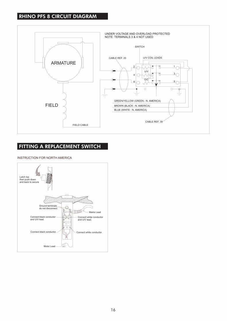
Note: The Pacific Rhino PFS 8 Drum Sander featuresa fully protected circuit breaker which incorporates'Low Volt Protection'. This means that should themains supply be interrupted during use the switch willimmediately return to the 'OFF' position to protect theoperator. This feature, by preventing a circuit throughthe switch unless mains voltage is present, alsoprevents a full insulation (flash) test unless the testinstrument has ' ' facility.
If your instrument has this facility then:- replace theswitch cover 'A' taking care to avoid trapping leadsand ensuring that all dust gaskets are correctlypositioned. Check that the circuit breaker 'ON'button does not lock in the 'ON' position whendepressed. The button must only lock 'ON' whencurrent is present. Before carrying out test ensure thatthe motor is connected by the twist lock socket Ref. 24and that all safety measures have been taken.
Electrical Testing
CAUTION - testing for electrical safetyshould be undertaken by a competentperson and all results recorded. Do notexceed 1250 volt insulation test durationof 3 seconds.
test on run
10
Carry out 'test on run' procedure.
If your instrument does not have 'test on run' facilitythen Continue as follows:-
5. While you have the switch housing open forvisual inspection remove the circuit breakercover 'B' together with the 'low volt coil 'C'(seebelow). Do not disconnect or disturb any cables.The 'low volt coils will remain within the cover 'B'.
The circuit breaker will now lock into the 'ON'position without current present. Before carryingout an insulation (flash) test ensure that the motoris connected by the twist lock socket Ref. 24 andthat all safety measures have been taken.
6. Use the standard test for electrical safety for agrounded (earthed) appliance. Do not exceed1250 volt insulation test duration of 3 seconds
7. Record the test results.
8. Complete a functional (run) test and recordresults.
9. After carrying out the tests disconnect themachine from the test station and snap the 'LowVolt Coil' 'C' back into position and replace cover'B'.
10. Replace the switch cover 'A' taking care to avoidtrapping leads and ensuring that all dust gasketsare correctly positioned. Check that the circuitbreaker 'ON' button does not lock in the 'ON'position when depressed. The button must onlylock 'ON' when current is present.
11. Finally test the machine once again to ensuregood earth and insulation of the mains cableand switch. Do not exceed 1250 volt flashduration of 3 seconds.
CAUTION - when undertaking afunctional test ensure that the machine issecure, remember the sanding drum willrotate, ensure that the drum cannot comeinto contact with the work bench/servicearea.
11
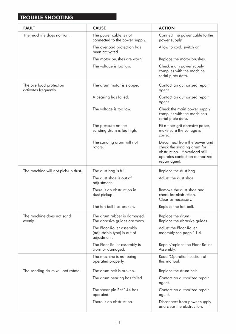
TROUBLE SHOOTING
FAULT CAUSE ACTION
The machine does not run. The power cable is not Connect the power cable to theconnected to the power supply. power supply.
The overload protection has Allow to cool, switch on.been activated.
The motor brushes are worn. Replace the motor brushes.
The voltage is too low. Check main power supplycomplies with the machineserial plate data.
The overload protection The drum motor is stopped. Contact an authorized repairactivates frequently. agent.
A bearing has failed. Contact an authorized repairagent.
The voltage is too low. Check the main power supplycomplies with the machine'sserial plate data.
The pressure on the Fit a finer grit abrasive paper,sanding drum is too high. make sure the voltage is
correct.
The sanding drum will not Disconnect from the power androtate. check the sanding drum for
obstruction. If overload stilloperates contact an authorizedrepair agent.
The machine will not pick-up dust. The dust bag is full. Replace the dust bag.
The dust shoe is out of Adjust the dust shoe.adjustment.
There is an obstruction in Remove the dust shoe anddust pickup. check for obstruction.
Clear as necessary.
The fan belt has broken. Replace the fan belt.
The Floor Roller assembly Adjust the Floor Roller(adjustable type) is out of a
The Floor Roller assembly is Repair/replace the Floor Rollerworn or damaged. Assembly.
The machine is not being Read ‘Operation’ section ofoperated properly. this manual.
The sanding drum will not rotate. The drum belt is broken. Replace the drum belt.
The drum bearing has failed. Contact an authorized repairagent.
The shear pin Ref.144 has Contact an authorized repairoperated. agent.
There is an obstruction. Disconnect from power supplyand clear the obstruction.
The machine does not sand The drum rubber is damaged. Replace the drum.evenly. The abrasive guides are worn. Replace the abrasive guides.
ssembly see page 11.4adjustment.
12
RHINO PFS 8 PARTS DIAGRAM
39
7
11
10
14
19
15
16
26
21
17
17
18
45
20
59
55
24
51
52
53
50
96
53
56
67
60
65
66
64
6361
62
83
81
752
78
86
73
72
36
35
2880
79
29
142
152
144
142
143
145 146
84
82
77
86
74
58
5423
9
1
23
4
22
12
6
58
12785
48
25
200
57
201
{
49 4647
66
27
Floor Sander
13
RHINO PFS 8 PARTS DIAGRAM
HT8 EX MULTI-SPEEDDRUM FLOOR SANDER
OWNERS MANUAL & OPERATING INSTRUCTIONS
APRIL 2006 REF. 179 PART # 024960
PRIN
TED
INTH
EU
K
© Hiretech
���
From Serial Number(220/240 Volt) & (110/120 Volt)
174
173169
149
98
176
250
31
167
124
131
159
101
103
102
168
165
164
31
30140
109
104 100
117
115
116 119
121119
123
86127
125
128
126
130
97
101
103
102
129
11043
96113
125
111 114
118
98
34
98
99
92 91
96 95
93
170
62 89 88
87 62
93 96
97 102
103
86
94
179
SERV
ICE
TO
OL
PA
CIF
IC
14
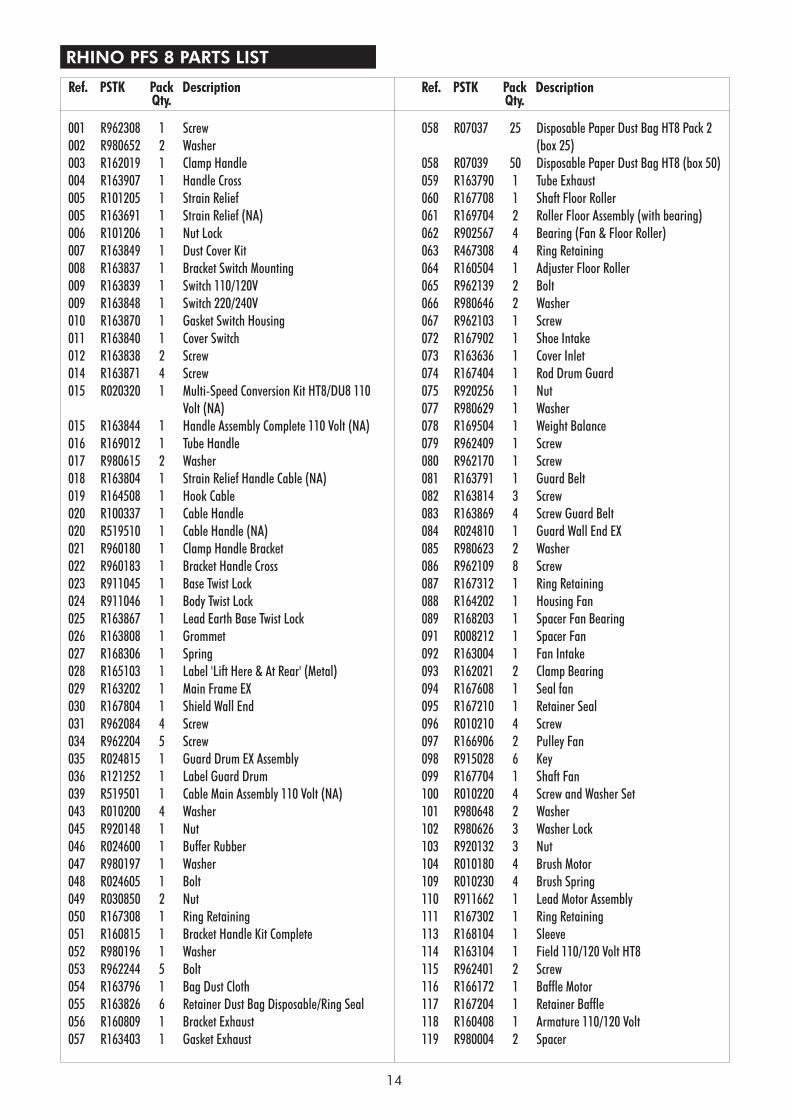
RHINO PFS 8 PARTS LIST
001 R962308 1 Screw002 R980652 2 Washer003 R162019 1 Clamp Handle004 R163907 1 Handle Cross005 R101205 1 Strain Relief005 R163691 1 Strain Relief (NA)006 R101206 1 Nut Lock007 R163849 1 Dust Cover Kit008 R163837 1 Bracket Switch Mounting009 R163839 1 Switch 110/120V009 R163848 1 Switch 220/240V010 R163870 1 Gasket Switch Housing011 R163840 1 Cover Switch012 R163838 2 Screw014 R163871 4 Screw015 R020320 1 Multi-Speed Conversion Kit HT8/DU8 110
Volt (NA)015 R163844 1 Handle Assembly Complete 110 Volt (NA)016 R169012 1 Tube Handle017 R980615 2 Washer018 R163804 1 Strain Relief Handle Cable (NA)019 R164508 1 Hook Cable020 R100337 1 Cable Handle020 R519510 1 Cable Handle (NA)021 R960180 1 Clamp Handle Bracket022 R960183 1 Bracket Handle Cross023 R911045 1 Base Twist Lock024 R911046 1 Body Twist Lock025 R163867 1 Lead Earth Base Twist Lock026 R163808 1 Grommet027 R168306 1 Spring028 R165103 1 Label 'Lift Here & At Rear' (Metal)029 R163202 1 Main Frame EX030 R167804 1 Shield Wall End031 R962084 4 Screw034 R962204 5 Screw035 R024815 1 Guard Drum EX Assembly036 R121252 1 Label Guard Drum039 R519501 1 Cable Main Assembly 110 Volt (NA)043 R010200 4 Washer045 R920148 1 Nut046 R024600 1 Buffer Rubber047 R980197 1 Washer048 R024605 1 Bolt049 R030850 2 Nut050 R167308 1 Ring Retaining051 R160815 1 Bracket Handle Kit Complete052 R980196 1 Washer053 R962244 5 Bolt054 R163796 1 Bag Dust Cloth055 R163826 6 Retainer Dust Bag Disposable/Ring Seal056 R160809 1 Bracket Exhaust057 R163403 1 Gasket Exhaust
058 R07037 25 Disposable Paper Dust Bag HT8 Pack 2(box 25)
058 R07039 50 Disposable Paper Dust Bag HT8 (box 50)059 R163790 1 Tube Exhaust060 R167708 1 Shaft Floor Roller061 R169704 2 Roller Floor Assembly (with bearing)062 R902567 4 Bearing (Fan & Floor Roller)063 R467308 4 Ring Retaining064 R160504 1 Adjuster Floor Roller065 R962139 2 Bolt066 R980646 2 Washer067 R962103 1 Screw072 R167902 1 Shoe Intake073 R163636 1 Cover Inlet074 R167404 1 Rod Drum Guard075 R920256 1 Nut077 R980629 1 Washer078 R169504 1 Weight Balance079 R962409 1 Screw080 R962170 1 Screw081 R163791 1 Guard Belt082 R163814 3 Screw083 R163869 4 Screw Guard Belt084 R024810 1 Guard Wall End EX085 R980623 2 Washer086 R962109 8 Screw087 R167312 1 Ring Retaining088 R164202 1 Housing Fan089 R168203 1 Spacer Fan Bearing091 R008212 1 Spacer Fan092 R163004 1 Fan Intake093 R162021 2 Clamp Bearing094 R167608 1 Seal fan095 R167210 1 Retainer Seal096 R010210 4 Screw097 R166906 2 Pulley Fan098 R915028 6 Key099 R167704 1 Shaft Fan100 R010220 4 Screw and Washer Set101 R980648 2 Washer102 R980626 3 Washer Lock103 R920132 3 Nut104 R010180 4 Brush Motor109 R010230 4 Brush Spring110 R911662 1 Lead Motor Assembly111 R167302 1 Ring Retaining113 R168104 1 Sleeve114 R163104 1 Field 110/120 Volt HT8115 R962401 2 Screw116 R166172 1 Baffle Motor117 R167204 1 Retainer Baffle118 R160408 1 Armature 110/120 Volt119 R980004 2 Spacer
Ref. PSTK Pack DescriptionQty.
Ref. PSTK Pack DescriptionQty.
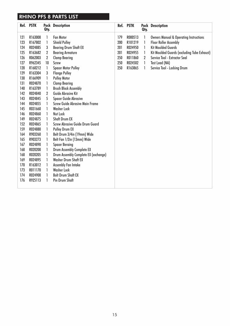
RHINO PFS 8 PARTS LIST
121 R163008 1 Fan Motor123 R167802 1 Shield Pulley124 R024885 3 Bearing Drum Shaft EX125 R163682 2 Bearing Armature126 R062003 2 Clamp Bearing127 R962345 10 Screw128 R168212 1 Spacer Motor Pulley129 R163304 3 Flange Pulley130 R166909 1 Pulley Motor131 R024870 1 Clamp Bearing140 R163789 1 Brush Block Assembly142 R024840 2 Guide Abrasive Kit143 R024845 5 Spacer Guide Abrasive144 R024855 1 Screw Guide Abrasive Main Frame145 R031660 1 Washer Lock146 R024860 1 Nut Lock149 R024875 1 Shaft Drum EX152 R024865 1 Screw Abrasive Guide Drum Guard159 R024880 1 Pulley Drum EX164 R903260 1 Belt Drum 3/4in (19mm) Wide165 R903273 1 Belt Fan 1/2in (13mm) Wide167 R024890 1 Spacer Beraing168 R020200 1 Drum Assembly Complete EX168 R020205 1 Drum Assembly Complete EX (exchange)169 R024895 1 Washer Drum Shaft EX170 R163012 1 Assembly Fan Intake173 R011170 1 Washer Lock174 R024900 1 Bolt Drum Shaft EX176 R925113 1 Pin Drum Shaft
15
Ref. PSTK Pack DescriptionQty.
Ref. PSTK Pack DescriptionQty.
179 R000513 1 Owners Manual & Operating Instructions200 R101219 1 Floor Roller Assembly201 R024950 1 Kit Moulded Guards201 R024955 1 Kit Moulded Guards (excluding Tube Exhaust)250 R011860 2 Service Tool - Extractor Seal250 R024502 1 Test Lead (NA)250 R163865 1 Service Tool - Locking Drum
16
RHINO PFS 8 CIRCUIT DIAGRAMimited
ARMATURE
FIELD
FIELD CABLE
CABLE REF. 39
2 1
43
6 5
U/V
O/C
CABLE REF. 20
SWITCH
UNDER VOLTAGE AND OVERLOAD PROTECTEDNOTE: TERMINALS 3 & 4 NOT USED
U/V COIL LEADS
GREEN/YELLOW (GREEN - N. AMERICA)
BROWN (BLACK - N. AMERICA)
BLUE (WHITE - N. AMERICA)
FITTING A REPLACEMENT SWITCH
2 4 6
INSTRUCTION FOR NORTH AMERICA
CE () U. AC960V CSN EN 60947T-4-1
OEZ
1
STOP START
I. ??-??ATEST
AC 3
SM1-10
53
Latch topthen push downand back to secure
Ground terminalsdo not disconnect.
Connect black conductorand U/V lead.
Connect black conductor. Connect white conductor.
Connect white conductorand U/V lead.
Motor Lead
Mains Lead
17
SERVICE & REPAIR
Contact your reseller for the name of your local service agent. Service and repairs undertaken by non-approvedservice agents will void the product warranty. If you should have difficulty in obtaining service please contact PacificFloor Care at the following address.
Pacific Floor Care2259 S. Sheridan RoadMUSKEGONMI 49442-6252
Tel: 1-800-968-1332 , 1-231-773-1330Fax: 1-800-863-9536
Web: www.pacificfloorcare.com
PACIFIC LIMITED WARRANTY
Pacific Floor Care warrants to the original purchaser that the Pacific Floor Care machine covered by this warrantyis free from defects in workmanship and materials. Should any part fail in the period of two years from the date ofthe original purchase as a result of a defect, Pacific Floor Care will (at it’s option) either repair or replace the partwithout charge provided that the machine has been operated in accordance with the Owners Manual andOperating Instructions.
Should any such defect arise, please contact your nearest authorized repair agent. Standard service over landmainland freight costs will be refunded on warranty repairs at the sole discretion of Pacific Floor Care or theauthorized repair agent. If the repair is non-warranty, the customer will be advised before any work is undertaken.
This warranty is the sole warranty by Pacific Floor Care and is in lieu of all other warranties express or implied andreleases Pacific Floor Care from all other obligations and liabilities.
This warranty does not apply to normal wear and tear to the machine, and in particular does not cover normalwear parts such as mains cable, wheels, switches, relays, brushes, rubber parts, hoses and bearings. Thiswarranty also does not cover, and Pacific Floor Care will not be liable for, excessive wear caused by abnormal use.
Pacific Floor Care will under no circumstances be liable for alterations to the machine or for damage caused bythird persons, or for misuse or abuse of the machine, or damage caused during transportation. Repairs of themachine made or attempted by persons other than those specifically authorized by Pacific Floor Care shall renderthis warranty void and Pacific Floor Care will not be liable for such repairs, the cost of such repairs, or theconsequences of such repairs. Where spare parts are used on the machine and they do not conform to PacificFloor Care specifications, this warranty will be rendered void and Pacific Floor Care will not be liable.
Pacific Floor Care will not be liable for any indirect or consequential loss, damage, cost or expense of any kindwhatever and however caused whether arising under contract, tort (including negligence) or otherwise including(without limitation) loss of production, loss of profits or contracts or of operating time or goodwill or anticipatedsavings.
PACIFIC FLOOR CARE2259 South Sheridan, Muskegon, MI 49442Tel: 1-800-968-1332 Fax: 1-800-863-9536
Every effort has been made to present all information in this publication accurately, however no liability isaccepted for any inclusions or advice given or for omissions from this publication. Pacific Floor Care reserves theright to make changes or improvements to its products without prior notice.