PacDrive Logic Motion Controller - LMC Eco - Hardware ...
165
EIO0000001501.06 www.schneider-electric.com PacDrive Logic Motion Controller EIO0000001501 02/2020 PacDrive Logic Motion Controller LMC Eco Hardware Guide Original instructions 02/2020
Transcript of PacDrive Logic Motion Controller - LMC Eco - Hardware ...

PacDrive Logic Motion Controller
EIO0000001501 02/2020
EIO
0000
0015
01.0
6
www.schneider-electric.com
PacDrive Logic Motion ControllerLMC EcoHardware GuideOriginal instructions
02/2020

The information provided in this documentation contains general descriptions and/or technical characteristics of the performance of the products contained herein. This documentation is not intended as a substitute for and is not to be used for determining suitability or reliability of these products for specific user applications. It is the duty of any such user or integrator to perform the appropriate and complete risk analysis, evaluation and testing of the products with respect to the relevant specific application or use thereof. Neither Schneider Electric nor any of its affiliates or subsidiaries shall be responsible or liable for misuse of the information contained herein. If you have any suggestions for improvements or amendments or have found errors in this publication, please notify us. You agree not to reproduce, other than for your own personal, noncommercial use, all or part of this document on any medium whatsoever without permission of Schneider Electric, given in writing. You also agree not to establish any hypertext links to this document or its content. Schneider Electric does not grant any right or license for the personal and noncommercial use of the document or its content, except for a non-exclusive license to consult it on an "as is" basis, at your own risk. All other rights are reserved.All pertinent state, regional, and local safety regulations must be observed when installing and using this product. For reasons of safety and to help ensure compliance with documented system data, only the manufacturer should perform repairs to components.When devices are used for applications with technical safety requirements, the relevant instructions must be followed. Failure to use Schneider Electric software or approved software with our hardware products may result in injury, harm, or improper operating results.Failure to observe this information can result in injury or equipment damage.© 2020 Schneider Electric. All rights reserved.
2 EIO0000001501 02/2020

Table of Contents
Safety Information. . . . . . . . . . . . . . . . . . . . . . . . . . . . . . 7About the Book . . . . . . . . . . . . . . . . . . . . . . . . . . . . . . . . 9
Chapter 1 Specific Safety Information . . . . . . . . . . . . . . . . . . . . . . . 13Product Related Information . . . . . . . . . . . . . . . . . . . . . . . . . . . . . . . . 14Intended Use . . . . . . . . . . . . . . . . . . . . . . . . . . . . . . . . . . . . . . . . . . . . 18
Chapter 2 System Overview . . . . . . . . . . . . . . . . . . . . . . . . . . . . . . 21System Overview. . . . . . . . . . . . . . . . . . . . . . . . . . . . . . . . . . . . . . . . . 22Logic Motion Controller . . . . . . . . . . . . . . . . . . . . . . . . . . . . . . . . . . . . 23Lexium 62 Drive System . . . . . . . . . . . . . . . . . . . . . . . . . . . . . . . . . . . 24Lexium 52 . . . . . . . . . . . . . . . . . . . . . . . . . . . . . . . . . . . . . . . . . . . . . . 28Lexium 62 Servo Drive . . . . . . . . . . . . . . . . . . . . . . . . . . . . . . . . . . . . 29SH3 Servo Motor . . . . . . . . . . . . . . . . . . . . . . . . . . . . . . . . . . . . . . . . . 30TM5 System . . . . . . . . . . . . . . . . . . . . . . . . . . . . . . . . . . . . . . . . . . . . 32Type Code . . . . . . . . . . . . . . . . . . . . . . . . . . . . . . . . . . . . . . . . . . . . . . 33Nameplate Descriptions . . . . . . . . . . . . . . . . . . . . . . . . . . . . . . . . . . . 34
Chapter 3 Planning . . . . . . . . . . . . . . . . . . . . . . . . . . . . . . . . . . . . . 353.1 Electromagnetic Compatibility (EMC) . . . . . . . . . . . . . . . . . . . . . . . . . 36
Electromagnetic Compatibility, EMC . . . . . . . . . . . . . . . . . . . . . . . . . . 363.2 Control Cabinet Planning. . . . . . . . . . . . . . . . . . . . . . . . . . . . . . . . . . . 40
Degree of Protection (IP) . . . . . . . . . . . . . . . . . . . . . . . . . . . . . . . . . . . 41Mechanical and Climatic Environmental Conditions in the Control Cabinet . . . . . . . . . . . . . . . . . . . . . . . . . . . . . . . . . . . . . . . . . . . . . . . . 42Using Cooling Units . . . . . . . . . . . . . . . . . . . . . . . . . . . . . . . . . . . . . . . 43
3.3 Information about Wiring . . . . . . . . . . . . . . . . . . . . . . . . . . . . . . . . . . . 45General Information about Wiring . . . . . . . . . . . . . . . . . . . . . . . . . . . . 46Cable Characteristics . . . . . . . . . . . . . . . . . . . . . . . . . . . . . . . . . . . . . 47Configuring and Coding the Cables. . . . . . . . . . . . . . . . . . . . . . . . . . . 48ESD Protection Measures . . . . . . . . . . . . . . . . . . . . . . . . . . . . . . . . . . 49
Chapter 4 Installation and Maintenance . . . . . . . . . . . . . . . . . . . . . 514.1 Commissioning . . . . . . . . . . . . . . . . . . . . . . . . . . . . . . . . . . . . . . . . . . 52
Prerequisites for Commissioning. . . . . . . . . . . . . . . . . . . . . . . . . . . . . 53Preparing Commissioning . . . . . . . . . . . . . . . . . . . . . . . . . . . . . . . . . . 54Preparing the Control Cabinet . . . . . . . . . . . . . . . . . . . . . . . . . . . . . . . 56
EIO0000001501 02/2020 3
Mechanical Mounting . . . . . . . . . . . . . . . . . . . . . . . . . . . . . . . . . . . . . . 59Wiring of the Controller . . . . . . . . . . . . . . . . . . . . . . . . . . . . . . . . . . . . 60Completion of Commissioning . . . . . . . . . . . . . . . . . . . . . . . . . . . . . . . 63Performing the Function Test. . . . . . . . . . . . . . . . . . . . . . . . . . . . . . . . 64
4.2 Maintenance, Repair, Cleaning, Replacement Equipment Inventory. . 65Prerequisites for Maintenance, Repair, and Cleaning . . . . . . . . . . . . . 66Repair. . . . . . . . . . . . . . . . . . . . . . . . . . . . . . . . . . . . . . . . . . . . . . . . . . 68Cleaning . . . . . . . . . . . . . . . . . . . . . . . . . . . . . . . . . . . . . . . . . . . . . . . . 69Battery, Real-Time Clock . . . . . . . . . . . . . . . . . . . . . . . . . . . . . . . . . . . 70Replacement Equipment Inventory . . . . . . . . . . . . . . . . . . . . . . . . . . . 71
4.3 Replacing Components and Cables. . . . . . . . . . . . . . . . . . . . . . . . . . . 72Prerequisites for Replacing Components and Cables . . . . . . . . . . . . . 73Device Replacement . . . . . . . . . . . . . . . . . . . . . . . . . . . . . . . . . . . . . . 76Fast Device Replacement (FDR) - Introduction . . . . . . . . . . . . . . . . . . 78Fast Device Replacement - Usage . . . . . . . . . . . . . . . . . . . . . . . . . . . 79Fast Device Replacement - Controller Display . . . . . . . . . . . . . . . . . . 81Fast Device Replacement - Application . . . . . . . . . . . . . . . . . . . . . . . . 84Cable Replacement . . . . . . . . . . . . . . . . . . . . . . . . . . . . . . . . . . . . . . . 89
Chapter 5 Indicators and Control Elements . . . . . . . . . . . . . . . . . . . 91Indicators of the Controller . . . . . . . . . . . . . . . . . . . . . . . . . . . . . . . . . . 92Menu Navigation . . . . . . . . . . . . . . . . . . . . . . . . . . . . . . . . . . . . . . . . . 97SD Card Slot . . . . . . . . . . . . . . . . . . . . . . . . . . . . . . . . . . . . . . . . . . . . 101USB Connection. . . . . . . . . . . . . . . . . . . . . . . . . . . . . . . . . . . . . . . . . . 105
Chapter 6 Integrated Communication Ports . . . . . . . . . . . . . . . . . . . 107Electrical Connections Overview . . . . . . . . . . . . . . . . . . . . . . . . . . . . . 108Connection Details Controller . . . . . . . . . . . . . . . . . . . . . . . . . . . . . . . 112
Chapter 7 Technical Data . . . . . . . . . . . . . . . . . . . . . . . . . . . . . . . . . 119Ambient Conditions . . . . . . . . . . . . . . . . . . . . . . . . . . . . . . . . . . . . . . . 120Standards and Regulations . . . . . . . . . . . . . . . . . . . . . . . . . . . . . . . . . 121Mechanical and Electrical Data . . . . . . . . . . . . . . . . . . . . . . . . . . . . . . 122Dimensions . . . . . . . . . . . . . . . . . . . . . . . . . . . . . . . . . . . . . . . . . . . . . 125
Chapter 8 Optional Modules . . . . . . . . . . . . . . . . . . . . . . . . . . . . . . . 1278.1 Communication Module Realtime Ethernet . . . . . . . . . . . . . . . . . . . . . 128
Overview . . . . . . . . . . . . . . . . . . . . . . . . . . . . . . . . . . . . . . . . . . . . . . . 129Mechanical Installation. . . . . . . . . . . . . . . . . . . . . . . . . . . . . . . . . . . . . 131Electrical Connections . . . . . . . . . . . . . . . . . . . . . . . . . . . . . . . . . . . . . 134
4 EIO0000001501 02/2020

8.2 Communication Module PROFIBUS DP . . . . . . . . . . . . . . . . . . . . . . . 145Overview . . . . . . . . . . . . . . . . . . . . . . . . . . . . . . . . . . . . . . . . . . . . . . . 146Mechanical Installation . . . . . . . . . . . . . . . . . . . . . . . . . . . . . . . . . . . . 147Electrical Connections . . . . . . . . . . . . . . . . . . . . . . . . . . . . . . . . . . . . . 150
Appendices . . . . . . . . . . . . . . . . . . . . . . . . . . . . . . . . . . . . . . . . . 153Appendix A Further Information on the Manufacturer . . . . . . . . . . . . 155
Contact Addresses . . . . . . . . . . . . . . . . . . . . . . . . . . . . . . . . . . . . . . . 156Product Training Courses . . . . . . . . . . . . . . . . . . . . . . . . . . . . . . . . . . 157
Appendix B Disposal . . . . . . . . . . . . . . . . . . . . . . . . . . . . . . . . . . . . . 159Disposal. . . . . . . . . . . . . . . . . . . . . . . . . . . . . . . . . . . . . . . . . . . . . . . . 159
Appendix C Units and Conversion Tables . . . . . . . . . . . . . . . . . . . . . 161Units and Conversion Tables . . . . . . . . . . . . . . . . . . . . . . . . . . . . . . . 161
Index . . . . . . . . . . . . . . . . . . . . . . . . . . . . . . . . . . . . . . . . . 165
EIO0000001501 02/2020 5

6 EIO0000001501 02/2020
Safety Information
Important Information
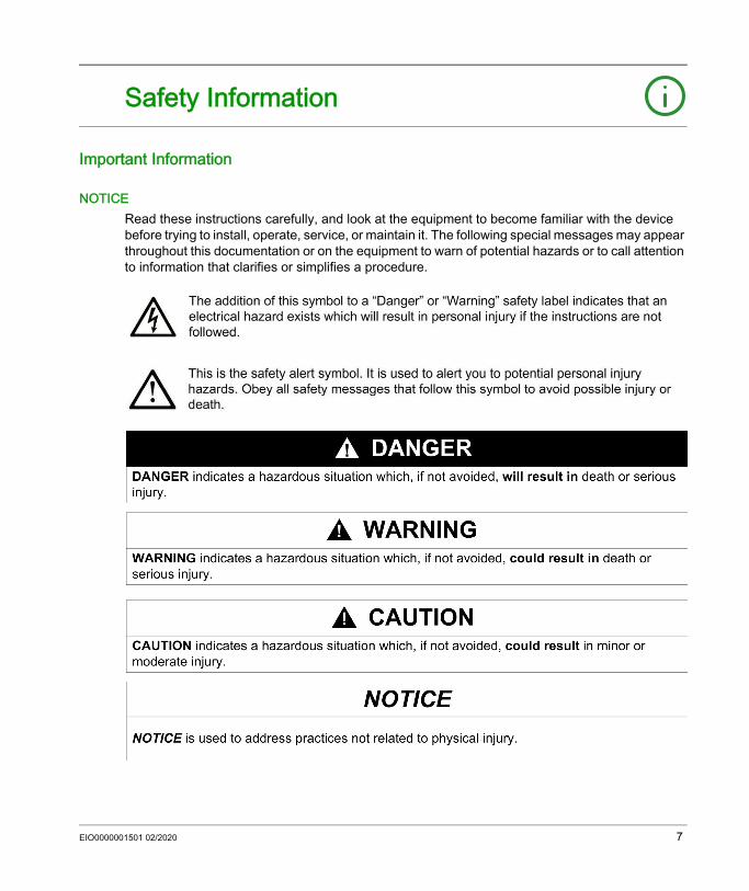
NOTICERead these instructions carefully, and look at the equipment to become familiar with the device before trying to install, operate, service, or maintain it. The following special messages may appear throughout this documentation or on the equipment to warn of potential hazards or to call attention to information that clarifies or simplifies a procedure.
EIO0000001501 02/2020 7
PLEASE NOTEElectrical equipment should be installed, operated, serviced, and maintained only by qualified personnel. No responsibility is assumed by Schneider Electric for any consequences arising out of the use of this material.A qualified person is one who has skills and knowledge related to the construction and operation of electrical equipment and its installation, and has received safety training to recognize and avoid the hazards involved.
QUALIFICATION OF PERSONNELOnly appropriately trained persons who are familiar with and understand the contents of this manual and all other pertinent product documentation are authorized to work on and with this product. The qualified person must be able to detect possible hazards that may arise from parameterization, modifying parameter values and generally from mechanical, electrical, or electronic equipment. The qualified person must be familiar with the standards, provisions, and regulations for the prevention of industrial accidents, which they must observe when designing and implementing the system.
INTENDED USEThe products described or affected by this document, together with software, accessories, and options, are programmable logic controllers (referred to herein as “logic controllers”), intended for industrial use according to the instructions, directions, examples, and safety information contained in the present document and other supporting documentation.The product may only be used in compliance with all applicable safety regulations and directives, the specified requirements, and the technical data.Prior to using the product, you must perform a risk assessment in view of the planned application. Based on the results, the appropriate safety-related measures must be implemented.Since the product is used as a component in an overall machine or process, you must ensure the safety of persons by means of the design of this overall system.Operate the product only with the specified cables and accessories. Use only genuine accessories and spare parts.Any use other than the use explicitly permitted is prohibited and can result in unanticipated hazards.
8 EIO0000001501 02/2020

About the Book
At a Glance
Document ScopeRead and understand the material contained in this manual before you work on the controller for the first time. Take particular note of the safety information (see page 13). As described in the section Qualification of Personnel (see page 8), only those persons who meet the Selection and qualification of employees are allowed to work at the controller.A copy of this manual must be available for personnel who work at the controller.This manual is supposed to help you use the capabilities of the controller safely and properly.Follow the instructions within this manual to: Avoid risks Reduce repair costs and downtime of the controller Increase the service life of the controller Increase reliability of the controller
Validity Note
This document has been updated for the release of EcoStruxureTM Machine Expert V1.2.1.The technical characteristics of the devices described in the present document also appear online. To access the information online:
Step Action1 Go to the Schneider Electric home page www.schneider-electric.com.2 In the Search box type the reference of a product or the name of a product range.
Do not include blank spaces in the reference or product range. To get information on grouping similar modules, use asterisks (*).
3 If you entered a reference, go to the Product Datasheets search results and click on the reference that interests you.If you entered the name of a product range, go to the Product Ranges search results and click on the product range that interests you.
4 If more than one reference appears in the Products search results, click on the reference that interests you.
5 Depending on the size of your screen, you may need to scroll down to see the datasheet.6 To save or print a datasheet as a .pdf file, click Download XXX product datasheet.
EIO0000001501 02/2020 9
The characteristics that are described in the present document should be the same as those characteristics that appear online. In line with our policy of constant improvement, we may revise content over time to improve clarity and accuracy. If you see a difference between the document and online information, use the online information as your reference.For product compliance and environmental information (RoHS, REACH, PEP, EOLI, etc.), go to www.schneider-electric.com/green-premium.
Related Documents
You can download these technical publications and other technical information from our website at www.schneider-electric.com/en/download.
Terminology Derived from StandardsThe technical terms, terminology, symbols and the corresponding descriptions in this manual, or that appear in or on the products themselves, are generally derived from the terms or definitions of international standards.In the area of functional safety systems, drives and general automation, this may include, but is not limited to, terms such as safety, safety function, safe state, fault, fault reset, malfunction, failure, error, error message, dangerous, etc.Among others, these standards include:
Document title ReferenceLexium 62 Hardware Guide EIO0000003738 (ENG);
EIO0000003740(GER);Lexium 52 Hardware Guide EIO0000001347 (ENG);
EIO0000001348 (GER);Lexium 62 ILM Hardware Guide EIO0000001351 (ENG);
EIO0000001352 (GER);SH3 Servo motor, Motor manual 0198441113987 (ENG)
0198441113988 (FRE)0198441113986 (GER)0198441113990 (SPA)0198441113989 (ITA)0198441113991 (CHS)
Standard DescriptionIEC 61131-2:2007 Programmable controllers, part 2: Equipment requirements and tests.ISO 13849-1:2015 Safety of machinery: Safety related parts of control systems.
General principles for design.EN 61496-1:2013 Safety of machinery: Electro-sensitive protective equipment.
Part 1: General requirements and tests.
10 EIO0000001501 02/2020

In addition, terms used in the present document may tangentially be used as they are derived from other standards such as:
Finally, the term zone of operation may be used in conjunction with the description of specific hazards, and is defined as it is for a hazard zone or danger zone in the Machinery Directive (2006/42/EC) and ISO 12100:2010.NOTE: The aforementioned standards may or may not apply to the specific products cited in the present documentation. For more information concerning the individual standards applicable to the products described herein, see the characteristics tables for those product references.
ISO 12100:2010 Safety of machinery - General principles for design - Risk assessment and risk reduction
EN 60204-1:2006 Safety of machinery - Electrical equipment of machines - Part 1: General requirements
ISO 14119:2013 Safety of machinery - Interlocking devices associated with guards - Principles for design and selection
ISO 13850:2015 Safety of machinery - Emergency stop - Principles for designIEC 62061:2015 Safety of machinery - Functional safety of safety-related electrical, electronic,
and electronic programmable control systemsIEC 61508-1:2010 Functional safety of electrical/electronic/programmable electronic safety-
related systems: General requirements.IEC 61508-2:2010 Functional safety of electrical/electronic/programmable electronic safety-
related systems: Requirements for electrical/electronic/programmable electronic safety-related systems.
IEC 61508-3:2010 Functional safety of electrical/electronic/programmable electronic safety-related systems: Software requirements.
IEC 61784-3:2016 Industrial communication networks - Profiles - Part 3: Functional safety fieldbuses - General rules and profile definitions.
2006/42/EC Machinery Directive2014/30/EU Electromagnetic Compatibility Directive2014/35/EU Low Voltage Directive
Standard DescriptionIEC 60034 series Rotating electrical machinesIEC 61800 series Adjustable speed electrical power drive systemsIEC 61158 series Digital data communications for measurement and control – Fieldbus for use in
industrial control systems
Standard Description
EIO0000001501 02/2020 11

12 EIO0000001501 02/2020
PacDrive Logic Motion ControllerSpecific Safety InformationEIO0000001501 02/2020
Specific Safety Information
Chapter 1Specific Safety Information
OverviewThis chapter contains important safety information regarding working with the controller. The controller conforms to recognized technical safety regulations.
What Is in This Chapter?This chapter contains the following topics:
Topic PageProduct Related Information 14Intended Use 18
EIO0000001501 02/2020 13

Specific Safety Information
Product Related Information
OverviewHealth and safety risks arising from the controller have been reduced. However a residual risk remains, since the controller works with electrical voltage and electrical currents.If activities involve residual risks, a safety message is made at the appropriate points. This includes potential hazard(s) that may arise, their possible consequences, and describes preventive measures to avoid the hazard(s).
Electrical Parts
DANGERHAZARD OF ELECTRIC SHOCK, EXPLOSION OR ARC FLASH Disconnect all power from all equipment including connected devices prior to removing any
covers or doors, or installing or removing any accessories, hardware, cables, or wires except under the specific conditions specified in the appropriate hardware guide for this equipment.
Always use a properly rated voltage sensing device to confirm the power is off where and when indicated.
Replace and secure all covers, accessories, hardware, cables, and wires and confirm that a proper ground connection exists before applying power to the unit.
Use only the specified voltage when operating this equipment and any associated products.Failure to follow these instructions will result in death or serious injury.
DANGERELECTRIC SHOCK, EXPLOSION, OR ARC FLASH Operate electrical components only with a connected protective ground (earth) cable. After the installation, verify the secure connection of the protective ground (earth) cable to all
electrical devices to ensure that connection complies with the connection diagram. Before enabling the device, safely cover the live components to prevent contact. Do not touch the electrical connection points of the components when the module is
energized. Provide protection against indirect contact. Connect and disconnect cables and terminals only after you have verified that the power has
been removed from the system.Failure to follow these instructions will result in death or serious injury.
14 EIO0000001501 02/2020

Specific Safety Information
Assembly and HandlingThis product has a leakage (touch) current greater than 3.5 mA. If the protective ground connection is interrupted, a hazardous leakage (touch) current may flow if the housing is touched.
Hazardous MovementsThere can be different sources of hazardous movements: No, or incorrect, homing of the drive Wiring or cabling errors Errors in the application program Component errors Error in the measured value and signal transmitterNOTE: Provide for personal safety by primary equipment monitoring or measures. Do not rely only on the internal monitoring of the drive components. Adapt the monitoring or other arrangements and measures to the specific conditions of the installation in accordance with a risk and error analysis.
DANGERINSUFFICIENT GROUNDING
Use a protective ground copper conductor with at least 10 mm2 (AWG 6) or two protective ground copper conductors with the same or larger cross section of the conductors supplying the power terminals.
Verify compliance with all local and national electrical code requirements as well as all other applicable regulations with respect to grounding of all equipment.
Failure to follow these instructions will result in death or serious injury.
WARNINGCRUSHING, SHEARING, CUTTING AND HITTING DURING HANDLING Observe the general construction and safety regulations for handling and assembly. Use appropriate mounting and transport equipment and use appropriate tools. Prevent clamping and crushing by taking appropriate precautions. Cover edges and angles to protect against cutting damage. Wear appropriate protective clothing (for example, protective goggles, protective boots,
protective gloves).Failure to follow these instructions can result in death, serious injury, or equipment damage.
EIO0000001501 02/2020 15
Specific Safety Information
Drive systems may perform unanticipated movements because of incorrect wiring, incorrect settings, incorrect data or other errors.
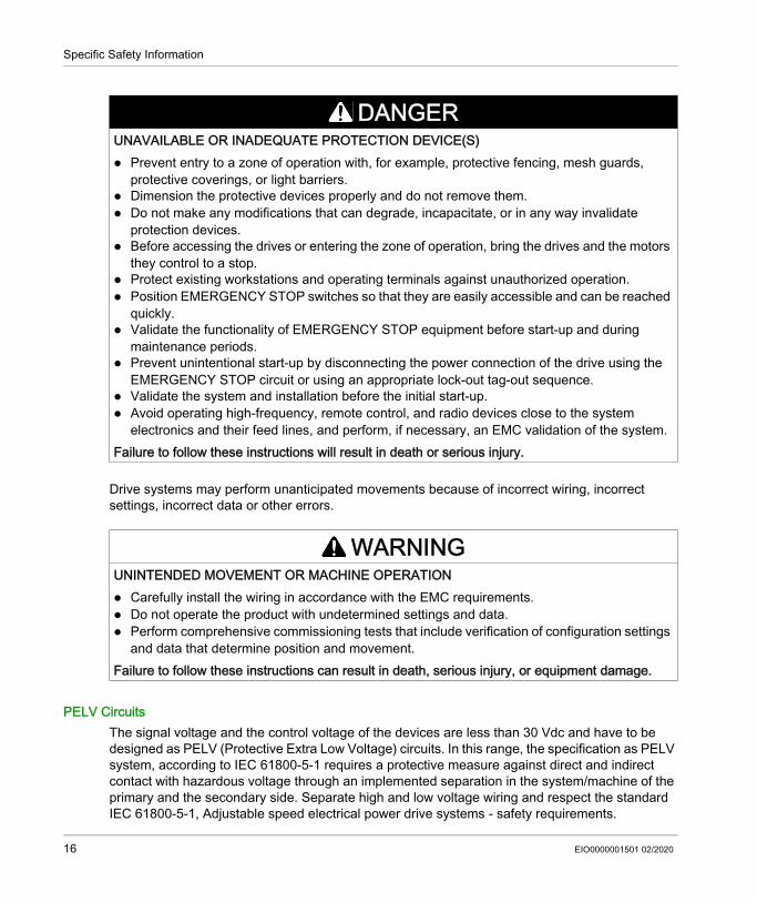
PELV CircuitsThe signal voltage and the control voltage of the devices are less than 30 Vdc and have to be designed as PELV (Protective Extra Low Voltage) circuits. In this range, the specification as PELV system, according to IEC 61800-5-1 requires a protective measure against direct and indirect contact with hazardous voltage through an implemented separation in the system/machine of the primary and the secondary side. Separate high and low voltage wiring and respect the standard IEC 61800-5-1, Adjustable speed electrical power drive systems - safety requirements.
DANGERUNAVAILABLE OR INADEQUATE PROTECTION DEVICE(S) Prevent entry to a zone of operation with, for example, protective fencing, mesh guards,
protective coverings, or light barriers. Dimension the protective devices properly and do not remove them. Do not make any modifications that can degrade, incapacitate, or in any way invalidate
protection devices. Before accessing the drives or entering the zone of operation, bring the drives and the motors
they control to a stop. Protect existing workstations and operating terminals against unauthorized operation. Position EMERGENCY STOP switches so that they are easily accessible and can be reached
quickly. Validate the functionality of EMERGENCY STOP equipment before start-up and during
maintenance periods. Prevent unintentional start-up by disconnecting the power connection of the drive using the
EMERGENCY STOP circuit or using an appropriate lock-out tag-out sequence. Validate the system and installation before the initial start-up. Avoid operating high-frequency, remote control, and radio devices close to the system
electronics and their feed lines, and perform, if necessary, an EMC validation of the system.Failure to follow these instructions will result in death or serious injury.
WARNINGUNINTENDED MOVEMENT OR MACHINE OPERATION Carefully install the wiring in accordance with the EMC requirements. Do not operate the product with undetermined settings and data. Perform comprehensive commissioning tests that include verification of configuration settings
and data that determine position and movement.Failure to follow these instructions can result in death, serious injury, or equipment damage.
16 EIO0000001501 02/2020

Specific Safety Information
Cyber Security
DANGERELECTRIC SHOCK DUE TO INADEQUATE PROTECTIVE SEPARATIONOnly connect devices, electrical components, or lines to the signal voltage connectors of these products that feature a sufficient, protective separation from the connected circuits in accordance with the standards (IEC 61800-5-1: Adjustable speed electrical power drive systems - safety requirements).Failure to follow these instructions will result in death or serious injury.
WARNINGUNAUTHENTICATED ACCESS AND SUBSEQUENT UNAUTHORIZED MACHINE OPERATION Evaluate whether your environment or your machines are connected to your critical
infrastructure and, if so, take appropriate steps in terms of prevention, based on Defense-in-Depth, before connecting the automation system to any network.
Limit the number of devices connected to a network to the minimum necessary. Isolate your industrial network from other networks inside your company. Protect any network against unintended access by using firewalls, VPN, or other, proven
security measures. Monitor activities within your systems. Prevent subject devices from direct access or direct link by unauthorized parties or unauthen-
ticated actions. Prepare a recovery plan including backup of your system and process information.Failure to follow these instructions can result in death, serious injury, or equipment damage.
EIO0000001501 02/2020 17

Specific Safety Information
Intended Use
InstallationInstall and operate this equipment in a control cabinet (enclosure) appropriately rated for its intended environment and secured by a keyed or tooled locking mechanism.
Provide for Protective MeasuresBefore installing the device, provide for appropriate protective devices in compliance with local and national standards. Do not commission components without appropriate protective devices. After installation, commissioning, or repair, test the protective devices used.Perform a risk evaluation concerning the specific use before operating the product and take appropriate safety measures.
If circumstances occur that affect the safety or cause changes to the operating behavior of the controllers, then immediately shut down the controllers and contact your Schneider Electric representative.
Use Original Equipment OnlyUse only the accessories and mounting parts specified in the documentation and no third-party devices or components that have not been expressly approved by Schneider Electric. There are no user-serviceable parts within the PacDrive LMC Eco components. Either replace the component or contact the Schneider Electric Customer Service.
WARNINGUNINTENDED EQUIPMENT OPERATIONEnsure that a risk assessment is conducted and respected according to EN/ISO 12100 during the design of your machine.Failure to follow these instructions can result in death, serious injury, or equipment damage.
WARNINGUNINTENDED EQUIPMENT OPERATION Only use software and hardware components approved by Schneider Electric for use with this
equipment. Do not attempt to service this equipment outside of authorized Schneider Electric service
centers. Update your application program every time you change the physical hardware configuration.Failure to follow these instructions can result in death, serious injury, or equipment damage.
18 EIO0000001501 02/2020

Specific Safety Information
Environment RestrictionsThe components must not be used in the following environments: In hazardous (explosive) atmospheres In mobile, movable, or floating systems In life support systems In domestic appliances UndergroundThis equipment has been designed to operate outside of any hazardous location. Only install this equipment in zones known to be free of a hazardous atmosphere.
DANGERPOTENTIAL FOR EXPLOSIONInstall and use this equipment in non-hazardous locations only.Failure to follow these instructions will result in death or serious injury.
EIO0000001501 02/2020 19

Specific Safety Information
20 EIO0000001501 02/2020
PacDrive Logic Motion ControllerSystem OverviewEIO0000001501 02/2020
System Overview
Chapter 2System Overview
What Is in This Chapter?This chapter contains the following topics:
Topic PageSystem Overview 22Logic Motion Controller 23Lexium 62 Drive System 24Lexium 52 28Lexium 62 Servo Drive 29SH3 Servo Motor 30TM5 System 32Type Code 33Nameplate Descriptions 34
EIO0000001501 02/2020 21

System Overview
System Overview
System OverviewThe control system consists of several components, depending on its application.PacDrive 3 system overview
1 EcoStruxure Machine Expert Software2 Safety Logic Controller according to IEC 61508 and ISO 13849
22 EIO0000001501 02/2020

System Overview
Logic Motion Controller
Overview
Product DescriptionThe PacDrive LMC (Logic Motion Controller), with a VxWorks real-time operating system, centrally implements the Logic Controller and motion functions. A PacDrive LMC synchronizes, coordinates, and creates the motion functions of a machine for a maximum of: 0 Sercos servo drives for the controller PacDrive LMC100 4 Sercos servo drives for the controller PacDrive LMC101 6 Sercos servo drives for the controller PacDrive LMC106 8 Sercos servo drives for the controller PacDrive LMC201 12 Sercos servo drives for the controller PacDrive LMC212 16 Sercos servo drives for the controller PacDrive LMC216 8 Sercos servo drives for the controller PacDrive LMC300 16 Sercos servo drives for the controller PacDrive LMC400 16 Sercos servo drives for the controller PacDrive LMC402 99 Sercos servo drives for the controller PacDrive LMC600 130 Sercos servo drives for the controller PacDrive LMC802
EIO0000001501 02/2020 23

System Overview
Lexium 62 Drive System
OverviewThe modular servo drive system Lexium 62 Drive System is designed for the operation of servo drives in a multi-axes system.The power electronic components of the Lexium 62 Drive System are fitted inside the control cabinet.
Lexium 62 Power Supply
Lexium 62 Connection Module
The Lexium 62 Drive System helps simplify the wiring of the devices in relation to the initial start-up and in service cases. This also applies to the cable connection of the enclosed devices to the field. All the connectors that can be connected from the outside (power input, DC bus, 24 Vdc supply, Sercos, Ready, and Inverter Enable) are designed such, that a fast and simple configuration without tools can be realized on the device.
Using a common DC bus, the central power supply unit Lexium 62 Power Supply supplies the connected servo converters with the power required.The central Lexium 62 Power Supply, using a common DC bus, supplies the connected Lexium 62 Servo Drives with the power required.
The Lexium 62 Connection Module supplies the Lexium 62 ILMs with DC voltage from the DC bus via a hybrid cable or via a power cable (daisy chain wiring). Additionally, the Lexium 62 Connection Module provides the Inverter Enable and Sercos interface.
24 EIO0000001501 02/2020

System Overview
Lexium 62 Distribution Box
The highlights: 1...4 connections for Lexium 62 ILMs or daisy chain lines or further Lexium 62 Distribution Box Easy wiring using pre-assembled hybrid cables or power cables (daisy chain wiring) Easy to expand
Lexium 62 ILM
The Lexium 62 ILMs are available in three different flange sizes: ILM070 ILM100 ILM140The highlights: Compact type of construction 3.5 times peak torque Integrated Sercos interface High-resolution single or multi-turn encoder Degree of protection IP65 Simple wiring
The Lexium 62 Distribution Box is the link between Lexium 62 Connection Module and Lexium 62 ILM. Depending on the number of drives, 1 to 4 Lexium 62 ILMs or daisy chain lines can be connected. When operating more than four drives, simply expand the system using one or more Lexium 62 Distribution Box.
The innovative Lexium 62 ILM combines motor, power stage, and digital servo controller for an axis in a space-saving housing. Due to its compact construction with the integrated controller, it is perfectly suitable for peripheral setup. It is available with individual or multi-turn encoders and configures itself with the aid of the electronic nameplate in the Lexium 62 ILM.
EIO0000001501 02/2020 25
System Overview
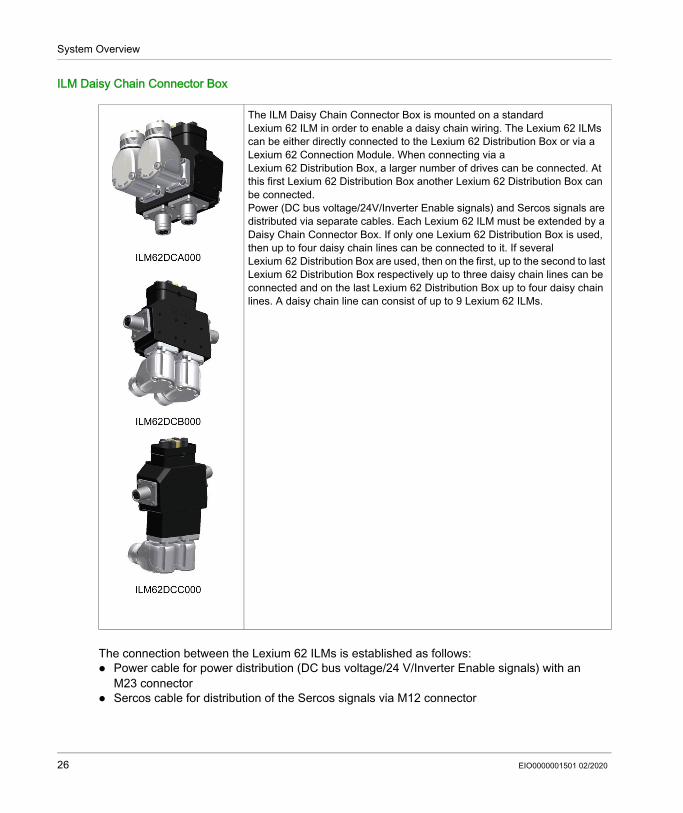
ILM Daisy Chain Connector Box
The connection between the Lexium 62 ILMs is established as follows: Power cable for power distribution (DC bus voltage/24 V/Inverter Enable signals) with an
M23 connector Sercos cable for distribution of the Sercos signals via M12 connector
The ILM Daisy Chain Connector Box is mounted on a standard Lexium 62 ILM in order to enable a daisy chain wiring. The Lexium 62 ILMs can be either directly connected to the Lexium 62 Distribution Box or via a Lexium 62 Connection Module. When connecting via a Lexium 62 Distribution Box, a larger number of drives can be connected. At this first Lexium 62 Distribution Box another Lexium 62 Distribution Box can be connected.Power (DC bus voltage/24V/Inverter Enable signals) and Sercos signals are distributed via separate cables. Each Lexium 62 ILM must be extended by a Daisy Chain Connector Box. If only one Lexium 62 Distribution Box is used, then up to four daisy chain lines can be connected to it. If several Lexium 62 Distribution Box are used, then on the first, up to the second to last Lexium 62 Distribution Box respectively up to three daisy chain lines can be connected and on the last Lexium 62 Distribution Box up to four daisy chain lines. A daisy chain line can consist of up to 9 Lexium 62 ILMs.
26 EIO0000001501 02/2020
System Overview
The following Lexium 62 ILMs can be equipped with the Daisy Chain Connector Box in order to implement a daisy chain wiring: ILM070•• ILM100•• ILM140••The Daisy Chain Connector Box is available in the following variants: ILM62DCA000 (suitable for ILM070••, ILM100•• and ILM140••) ILM62DCB000 (suitable for ILM070•• only) ILM62DCC000 (suitable for ILM100•• only)
EIO0000001501 02/2020 27
System Overview
Lexium 52
Overview
References
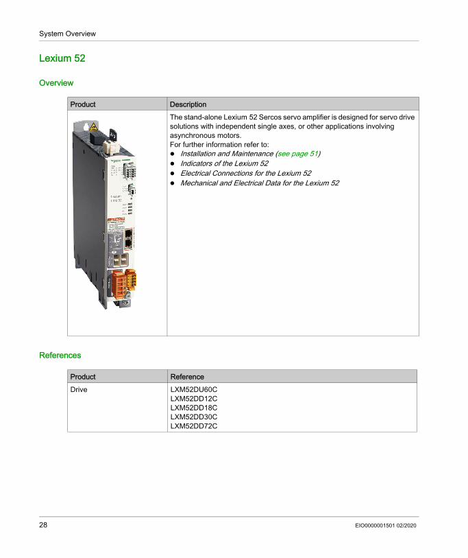
Product DescriptionThe stand-alone Lexium 52 Sercos servo amplifier is designed for servo drive solutions with independent single axes, or other applications involving asynchronous motors.For further information refer to: Installation and Maintenance (see page 51) Indicators of the Lexium 52 Electrical Connections for the Lexium 52 Mechanical and Electrical Data for the Lexium 52
Product ReferenceDrive LXM52DU60C
LXM52DD12CLXM52DD18CLXM52DD30C LXM52DD72C
28 EIO0000001501 02/2020
System Overview
Lexium 62 Servo Drive
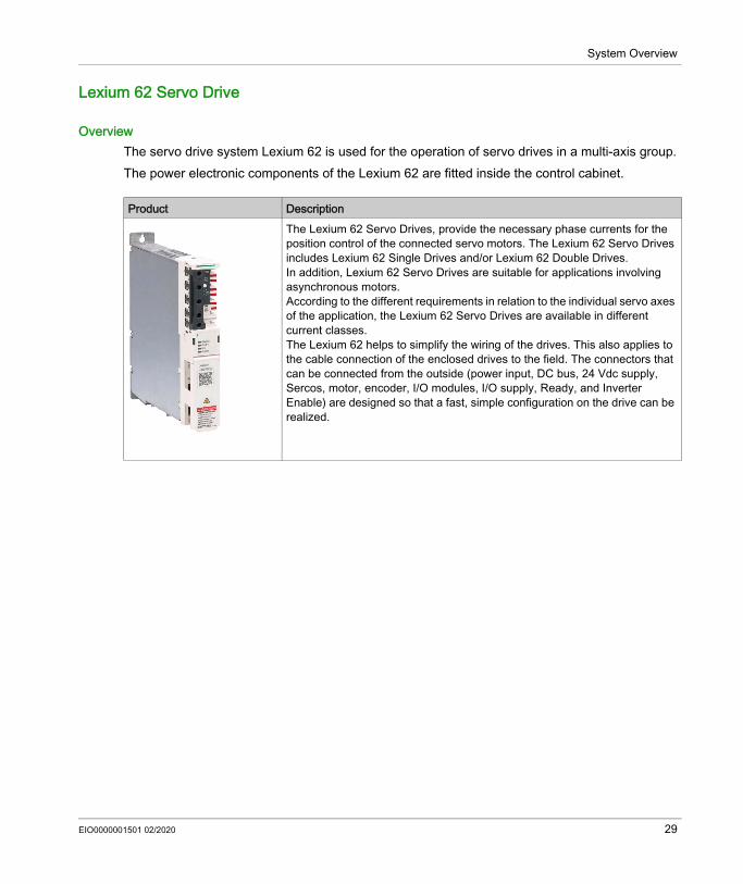
OverviewThe servo drive system Lexium 62 is used for the operation of servo drives in a multi-axis group.The power electronic components of the Lexium 62 are fitted inside the control cabinet.
Product DescriptionThe Lexium 62 Servo Drives, provide the necessary phase currents for the position control of the connected servo motors. The Lexium 62 Servo Drives includes Lexium 62 Single Drives and/or Lexium 62 Double Drives.In addition, Lexium 62 Servo Drives are suitable for applications involving asynchronous motors.According to the different requirements in relation to the individual servo axes of the application, the Lexium 62 Servo Drives are available in different current classes.The Lexium 62 helps to simplify the wiring of the drives. This also applies to the cable connection of the enclosed drives to the field. The connectors that can be connected from the outside (power input, DC bus, 24 Vdc supply, Sercos, motor, encoder, I/O modules, I/O supply, Ready, and Inverter Enable) are designed so that a fast, simple configuration on the drive can be realized.
EIO0000001501 02/2020 29

System Overview
SH3 Servo Motor
Overview
High Dynamic AC Servo MotorsBecause of the low inertia and a high overload capability, the motor SH3 fulfills many requirements concerning the accuracy, dynamics, and efficiency.The SH3 motors are available in six different flange sizes: SH3-040 (40 mm / 1.57 in.) SH3-055 (55 mm / 2.17 in.) SH3-070 (70 mm / 2.76 in.) SH3-100 (100 mm / 3.94 in.) SH3-140 (140 mm / 5.51 in.) SH3-205 (205 mm / 8.07 in.)
CharacteristicsThe motors have the following features: Overload protection by integrated temperature sensor (external evaluation required) Low moment of inertia High power density Excellent dynamics High overload capability Broad torque range Special winding for low phase currents Motor connection via circular connectors Easy commissioning via electronic nameplate in SinCos encoder Low maintenance
Product DescriptionThe SH3 motors are low-inertia AC synchronous servo motors designed for highly dynamic positioning tasks.A drive system consists of the servo motor and the drive. Maximum performance requires the motor and drive to be adapted to each other.
30 EIO0000001501 02/2020

System Overview
Options and AccessoriesThe motors are available with various options such as: Various encoder systems Holding brake Various shaft versions Various degrees of protection Various lengths Various sizes Various connection versionsFor further information, refer to the SH3 Servo Motor - User Guide.
EIO0000001501 02/2020 31
System Overview
TM5 System
OverviewThe direct connection of the TM5 System to the PacDrive LMC Eco is not possible. The TM5 System can be connected via the Sercos bus interface.
32 EIO0000001501 02/2020

System Overview
Type Code
OverviewThe graphic shows the type code PacDrive LMC Eco:
EIO0000001501 02/2020 33

System Overview
Nameplate Descriptions
OverviewThe technical nameplate of the Logic Motion Controller (LMC) drive is located on the left bottom side of the housing.Explanation of the technical nameplate entries:
The logistical nameplate of the LMC is located on top of the housing.
Label DescriptionLMCxxxCxxxxxx Device type and UnicodeInput d.c Digital inputs / input voltage and input current (per input) Output d.c. Digital outputs / output voltage and rated current (per input)IP20 Degree of protectionCE (symbol) CE mark
Label DescriptionLMC101CAA10000 Device type and Unicode907156.0010 Serial numberRS:02 Hardware revision (1)
DOM Date of manufacture(1) When replacing the controller (see page 76), the hardware revision for the previous and the new device
should be identical to help avoid potential compatibility issues with the equipment. The hardware revision can also be read from the hardware code in the device (see page 99). For more information on the compatibility of different hardware revisions, contact your local Schneider Electric representative.
34 EIO0000001501 02/2020

PacDrive Logic Motion ControllerPlanningEIO0000001501 02/2020
Planning
Chapter 3Planning
What Is in This Chapter?This chapter contains the following sections:
Section Topic Page3.1 Electromagnetic Compatibility (EMC) 363.2 Control Cabinet Planning 403.3 Information about Wiring 45
EIO0000001501 02/2020 35

Planning
Electromagnetic Compatibility (EMC)
Section 3.1Electromagnetic Compatibility (EMC)
Electromagnetic Compatibility, EMC
Electromagnetic Disturbances of Signals and DevicesThis product meets the EMC requirements in accordance with the standard IEC 61131-2, provided that the EMC measures described in this manual are complied with during installation.
These types of devices are not intended to be used on a low-voltage public network which supplies domestic premises. Radio frequency interference is expected if used in such a network.
WARNINGSIGNAL AND EQUIPMENT INTERFERENCE Only operate the drive with the specified external mains filter. Install the wiring in accordance with the EMC requirements described in the present
document. Verify compliance with the EMC requirements described in the present document. Verify compliance with all EMC regulations and requirements applicable in the country in
which the product is to be operated and with all EMC regulations and requirements applicable at the installation site.
Failure to follow these instructions can result in death, serious injury, or equipment damage.
WARNINGELECTROMAGNETIC DISTURBANCES OF SIGNALS AND DEVICESUse proper EMC shielding techniques to help prevent unintended device operation in accordance with the standard IEC 61800-3.Failure to follow these instructions can result in death, serious injury, or equipment damage.
WARNINGRADIO INTERFERENCEDo not use these products in domestic electrical networks.Failure to follow these instructions can result in death, serious injury, or equipment damage.
36 EIO0000001501 02/2020

Planning
Layout Control Cabinet (Enclosure)The prerequisite for compliance with the specified limit values is an EMC compatible layout. Depending on the application, the following measures can improve the EMC-dependent values:
Shielded Cables
Cable Installation
EMC measures ObjectiveUse galvanized or chromium-plated sub plates, bond metallic parts across large surface areas, remove paint layer from contact surfaces.
Good conductivity by surface area contact.
Ground control cabinet (enclosure), door, and sub plates by using grounding strips or grounding cables with a cross-section of 10 mm2 (AWG 6).
Reduce emission.
Supplement switch devices such as contactors, relays, or magnetic valves with interference suppression combinations or spark suppressor elements (for example, diodes, varistors, RC elements).
Reduces mutual interference.
Fit power and control components separately. Reduces mutual interference.
EMC measures ObjectiveConnect large surface areas of cable shields, use cable clamps and ground straps.
Reduce emission.
Ground shields of digital signal wires at both ends by connecting them to a large surface area or via conductive connector housings.
Reduce interference action on signal cables, reduce emissions.
Ground shield of analog signal cables directly on the device (signal input), insulate the shield at the other cable end or ground the same through a capacitor, such as 10 nF.
Reduce grounding loops by low frequency interferences.
EMC measures ObjectiveDo not route fieldbus cables and signal wires in a single cable duct together with lines with DC and AC voltages of more than 60 V. (Fieldbus cables, signal lines, and analog lines may be in the same cable duct) Recommendation: Use separate cable ducts at least 20 cm (7.84 in) apart.
Reduces mutual interference.
EIO0000001501 02/2020 37

Planning
Power Supply
Motor and Encoder CablesFrom an EMC perspective, motor supply cables and encoder cables are important. Only use pre-configured cables, or cables with the prescribed properties, and comply with the following EMC measures.
Keep cables as short as possible. Do not install unnecessary cable loops, use short cables from the central grounding point in the control cabinet to the external ground connection.
Reduces capacitive and inductive interference.
Use equipotential bonding conductors (stranded wire of equal potential at all grounding locations connected to an equipotential grounding plane) in the following cases: wide-area installations, different voltage supplies, and installation across several buildings.
Reduces current in the cable shield, reduces emissions.
Use stranded wire potential equalization conductor. Discharging of high frequency interference currents.If motor and machine are not conductively connected, for example by an insulated flange or a connection without surface contact, you must ground the motor with a ground strap or a ground wire. The conductor cross section must be at least 10 mm2 (AWG 6).
Reduces emissions, increases immunity.
Use twisted pair for 24 Vdc signals. Reduce interference action on signal cables, reduce emissions.
EMC measures Objective
EMC measures ObjectiveOperate product on mains with grounded neutral point.
Enables effectiveness of mains filter.
Use surge arrester if there is a risk of overvoltage. Reduces the risk of damage caused by overvoltage.
EMC measures ObjectiveDo not install switching elements in motor cables or encoder cables.
Reduces interference.
Route motor cable with a distance of at least 20 cm (7.84 in) to the signal cables or insert shield plates between the motor supply cable and the signal cable.
Reduces mutual interference.
For wiring that approaches the maximum cable distance specification (75 m/ 246.06 ft.), use equipotential bonding connection cables.
Reduce current on cable shield.
(1) If a cable must be cut through for installation purposes, the cables must be connected at the point of separation by using screen connections and metal housing.
38 EIO0000001501 02/2020
Planning
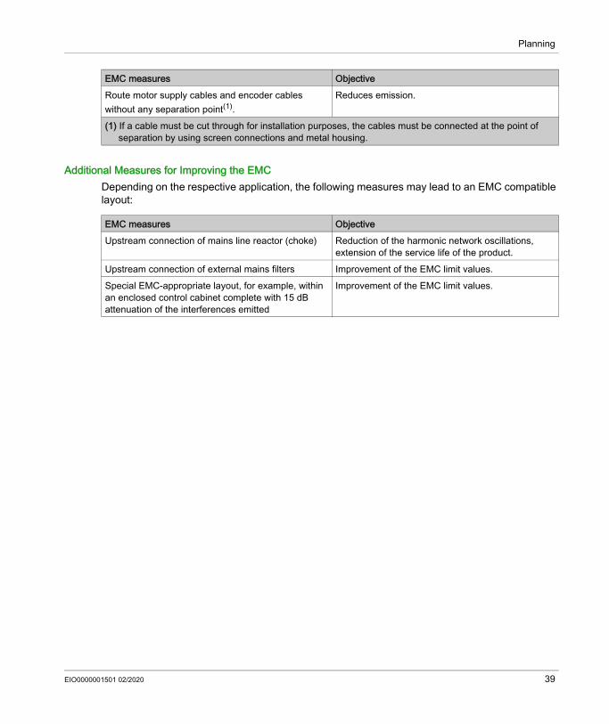
Additional Measures for Improving the EMCDepending on the respective application, the following measures may lead to an EMC compatible layout:
Route motor supply cables and encoder cables without any separation point(1).
Reduces emission.EMC measures Objective
(1) If a cable must be cut through for installation purposes, the cables must be connected at the point of separation by using screen connections and metal housing.
EMC measures ObjectiveUpstream connection of mains line reactor (choke) Reduction of the harmonic network oscillations,
extension of the service life of the product.Upstream connection of external mains filters Improvement of the EMC limit values.Special EMC-appropriate layout, for example, within an enclosed control cabinet complete with 15 dB attenuation of the interferences emitted
Improvement of the EMC limit values.
EIO0000001501 02/2020 39
Planning
Control Cabinet Planning
Section 3.2Control Cabinet Planning
What Is in This Section?This section contains the following topics:
Topic PageDegree of Protection (IP) 41Mechanical and Climatic Environmental Conditions in the Control Cabinet 42Using Cooling Units 43
40 EIO0000001501 02/2020
Planning
Degree of Protection (IP)
OverviewInstall components such that a degree of protection corresponding to the actual operational environment is set up.For more information on the degree of protection of the component, refer to Ambient Conditions (see page 120). The following ambient conditions may damage the components: Oil Moisture Electromagnetic interference Ambient temperature Metal dust deposits
WARNINGUNINTENDED EQUIPMENT OPERATION Prevent the formation of moisture during the operation, storage and transport of individual
components. Conform to the vibration and shock requirements specified in the operating manuals for the
components when operating, storing and transporting system components.Failure to follow these instructions can result in death, serious injury, or equipment damage.
EIO0000001501 02/2020 41

Planning
Mechanical and Climatic Environmental Conditions in the Control Cabinet
Overview
Step Action1 Observe the climatic and mechanical ambient conditions.
For more information on the general climatic and mechanical environmental conditions according to IEC 60721, refer to Ambient Conditions (see page 120).
2 Verify the technical data of the device whether the permitted deviations (for example, higher shock load or higher temperature) are specified.
42 EIO0000001501 02/2020
Planning
Using Cooling Units
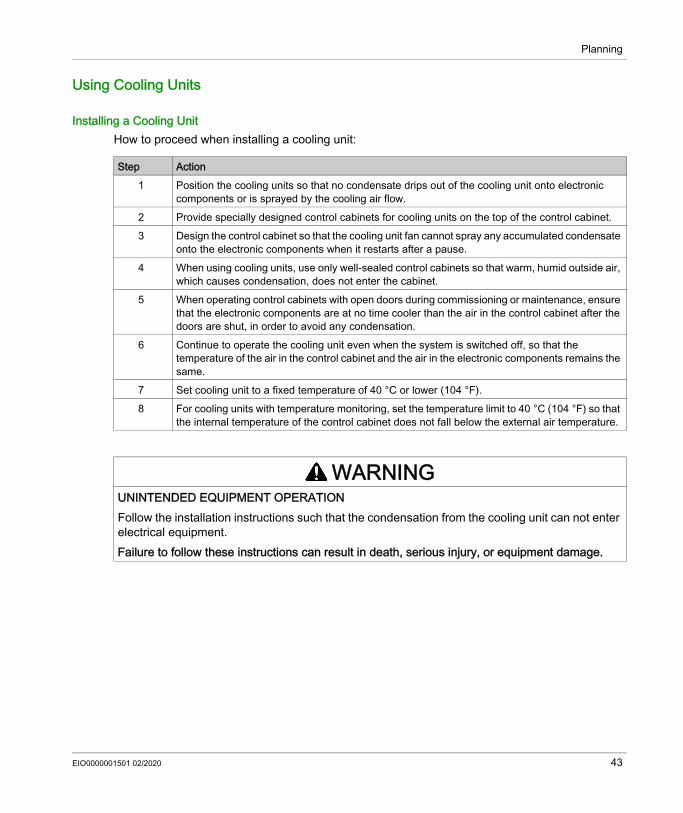
Installing a Cooling UnitHow to proceed when installing a cooling unit:
Step Action1 Position the cooling units so that no condensate drips out of the cooling unit onto electronic
components or is sprayed by the cooling air flow.2 Provide specially designed control cabinets for cooling units on the top of the control cabinet.3 Design the control cabinet so that the cooling unit fan cannot spray any accumulated condensate
onto the electronic components when it restarts after a pause.4 When using cooling units, use only well-sealed control cabinets so that warm, humid outside air,
which causes condensation, does not enter the cabinet.5 When operating control cabinets with open doors during commissioning or maintenance, ensure
that the electronic components are at no time cooler than the air in the control cabinet after the doors are shut, in order to avoid any condensation.
6 Continue to operate the cooling unit even when the system is switched off, so that the temperature of the air in the control cabinet and the air in the electronic components remains the same.
7 Set cooling unit to a fixed temperature of 40 °C or lower (104 °F).8 For cooling units with temperature monitoring, set the temperature limit to 40 °C (104 °F) so that
the internal temperature of the control cabinet does not fall below the external air temperature.
WARNINGUNINTENDED EQUIPMENT OPERATIONFollow the installation instructions such that the condensation from the cooling unit can not enter electrical equipment.Failure to follow these instructions can result in death, serious injury, or equipment damage.
EIO0000001501 02/2020 43

Planning
Installing a cooling unit
44 EIO0000001501 02/2020
Planning
Information about Wiring
Section 3.3Information about Wiring
What Is in This Section?This section contains the following topics:
Topic PageGeneral Information about Wiring 46Cable Characteristics 47Configuring and Coding the Cables 48ESD Protection Measures 49
EIO0000001501 02/2020 45

Planning
General Information about Wiring
OverviewUse only Schneider Electric approved devices in your application, and especially Schneider Electric pre-fabricated cables, wherever and whenever possible.Observe and implement the following points when wiring:1. Observe the minimum cross-sections of the cables necessary for the load carrying capacity of
the equipment being connected.2. Verify the integrity of cable shields to ensure continuity to ground.3. Ensure that there is a proper, equipotential connection to ground for all interconnected
equipment.4. Eliminate any ground loops.5. Do not disconnect cable connection terminals when under power.6. Ensure that all ground connections have sufficient surface area continuity.If, for example, two parallel conductors are shown as coming from one point, you may not run just one conductor and then branch it off at a later point. If it is wired this way, induction loops (interference emitters and antennas) as well as interfering potential shifts may occur.
DANGERINCORRECT OR UNAVAILABLE GROUNDINGRemove paint across a large surface at the installation points before installing the devices (bare metal connection).Failure to follow these instructions will result in death or serious injury.
46 EIO0000001501 02/2020

Planning
Cable Characteristics
OverviewCable characteristics of the Sercos cable (see the Schneider Electric catalog for the various cables available):
Property ValueVoltage isolation (jacket) 300 VdcTemperature range -20...+60 °C / -4...+140 °FCable diameter 5.8 ± 0.2 mm (0.23 ± 0.008 in.)Bending radius 8 x diameter (fixed routing)Sheath PVC, flame-retardantCable type and shielding CAT6 with S/FTP (Sercos III)
EIO0000001501 02/2020 47

Planning
Configuring and Coding the Cables
OverviewFor configuring and coding the cables, use the appropriate connector kit supplied with the device.
Accessory part Number Connection designationConnector digital inputs 2 CN7Connector digital outputs 2 CN8Connector supply voltage 1 CN9Connector TM5 (not used) 1 CN10Sercos cable 130 mm (5.11 in) 1 CN5, CN6Coding pin 6 CN7, CN8, CN9, CN10
48 EIO0000001501 02/2020
Planning
ESD Protection Measures
GeneralObserve the following instructions to help avoid damages due to electrostatic discharge:
NOTICEELECTROSTATIC DISCHARGE Do not touch any of the electrical connections or components. Prevent electrostatic charges, for example, by wearing appropriate clothing. If you must touch circuit boards, do so only on the edges. Remove existing static charge by touching a grounded, metallic surface.Failure to follow these instructions can result in equipment damage.
EIO0000001501 02/2020 49

Planning
50 EIO0000001501 02/2020

PacDrive Logic Motion ControllerInstallation and MaintenanceEIO0000001501 02/2020
Installation and Maintenance
Chapter 4Installation and Maintenance
What Is in This Chapter?This chapter contains the following sections:
Section Topic Page4.1 Commissioning 524.2 Maintenance, Repair, Cleaning, Replacement Equipment Inventory 654.3 Replacing Components and Cables 72
EIO0000001501 02/2020 51
Installation and Maintenance
Commissioning
Section 4.1Commissioning
What Is in This Section?This section contains the following topics:
Topic PagePrerequisites for Commissioning 53Preparing Commissioning 54Preparing the Control Cabinet 56Mechanical Mounting 59Wiring of the Controller 60Completion of Commissioning 63Performing the Function Test 64
52 EIO0000001501 02/2020
Installation and Maintenance
Prerequisites for Commissioning
Prerequisites
DANGERHAZARD OF ELECTRIC SHOCK, EXPLOSION OR ARC FLASH Disconnect all power from all equipment including connected devices prior to removing any
covers or doors, or installing or removing any accessories, hardware, cables, or wires except under the specific conditions specified in the appropriate hardware guide for this equipment.
Always use a properly rated voltage sensing device to confirm the power is off where and when indicated.
Replace and secure all covers, accessories, hardware, cables, and wires and confirm that a proper ground connection exists before applying power to the unit.
Use only the specified voltage when operating this equipment and any associated products.Failure to follow these instructions will result in death or serious injury.
DANGERELECTRIC SHOCK, EXPLOSION, OR ARC FLASH Operate electrical components only with a connected protective ground (earth) cable. After the installation, verify the secure connection of the protective ground (earth) cable to all
electrical devices to ensure that connection complies with the connection diagram. Before enabling the device, safely cover the live components to prevent contact. Do not touch the electrical connection points of the components when the module is
energized. Provide protection against indirect contact. Connect and disconnect cables and terminals only after you have verified that the power has
been removed from the system.Failure to follow these instructions will result in death or serious injury.
EIO0000001501 02/2020 53
Installation and Maintenance
Preparing Commissioning
PrerequisiteVerify safety-related circuits for proper function, if applicable.
ESD ProtectionObserve the following instructions to help avoid damages due to electrostatic discharge:
UnpackingHow to unpack the device:
NOTICEELECTROSTATIC DISCHARGE Do not touch any of the electrical connections or components. Prevent electrostatic charges, for example, by wearing appropriate clothing. If you must touch circuit boards, do so only on the edges. Remove existing static charge by touching a grounded, metallic surface.Failure to follow these instructions can result in equipment damage.
Step Action1 Remove packaging2 Dispose of the packaging material in accordance with the relevant local regulations.
54 EIO0000001501 02/2020

Installation and Maintenance
VerifyingHow to verify the device:
Step Action1 Verify that the delivery is complete, based on the delivery slip.2 Closely inspect the device for any signs of damage.3 Verify the data with the help of the nameplates.4 Observe requirements for the installation location.5 Then install LMC.
WARNINGUNINTENDED EQUIPMENT OPERATION Do not mount or commission damaged drive systems. Do not modify the drive systems. Send back inoperative devices.Failure to follow these instructions can result in death, serious injury, or equipment damage.
EIO0000001501 02/2020 55
Installation and Maintenance
Preparing the Control Cabinet
Overview
DANGERINCORRECT OR UNAVAILABLE GROUNDINGRemove paint across a large surface at the installation points before installing the devices (bare metal connection).Failure to follow these instructions will result in death or serious injury.
Step Action1 If necessary to maintain and respect the maximum ambient operating temperature, install
additional fan in the control cabinet.2 Do not block the fan air inlet of the product.3 Keep a distance of at least 100 mm (3.94 in) above and below the products.4 Mount the controller vertically inside the control cabinet.
56 EIO0000001501 02/2020

Installation and Maintenance
Assembly Distances, VentilationAssembly distances and air circulation:
Distance Air circulationa ≥ 100 mm (3.94 in) Clearance above the device.b ≥ 100 mm (3.94 in) Clearance below the device.c ≥ 60 mm (2.36 in) Clearance in front of the device.d ≥ 0 mm (0 in) Clearance between the device.
EIO0000001501 02/2020 57
Installation and Maintenance
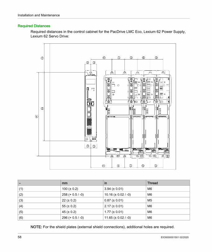
Required DistancesRequired distances in the control cabinet for the PacDrive LMC Eco, Lexium 62 Power Supply, Lexium 62 Servo Drive:
NOTE: For the shield plates (external shield connections), additional holes are required.
– mm in Thread(1) 100 (± 0.2) 3.94 (± 0.01) M6(2) 258 (+ 0.5 / -0) 10.16 (± 0.02 / -0) M6(3) 22 (± 0.2) 0.87 (± 0.01) M5(4) 55 (± 0.2) 2.17 (± 0.01) M6(5) 45 (± 0.2) 1.77 (± 0.01) M6(6) 296 (+ 0.5 / -0) 11.65 (± 0.02 / -0) M6
58 EIO0000001501 02/2020
Installation and Maintenance
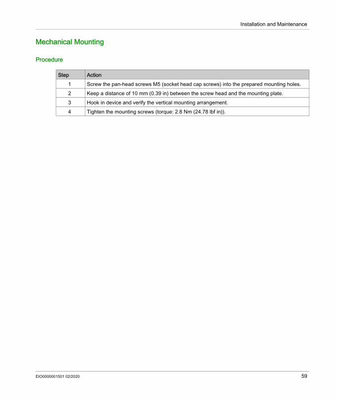
Mechanical Mounting
Procedure
Step Action1 Screw the pan-head screws M5 (socket head cap screws) into the prepared mounting holes.2 Keep a distance of 10 mm (0.39 in) between the screw head and the mounting plate.3 Hook in device and verify the vertical mounting arrangement.4 Tighten the mounting screws (torque: 2.8 Nm (24.78 lbf in)).
EIO0000001501 02/2020 59

Installation and Maintenance
Wiring of the Controller
Before Applying Power to Your Controller for the First TimeFor information on the connections mentioned hereafter, refer to the Electrical Connections Overview (see page 108).To wire the controller, proceed as follows:
Step Action1 Be sure that the controller is first connected to the ground (functional earth) before proceeding
with other connections.2 Verify the continuity of the grounding system of your application.3 Verify that all cable shields are properly connected to the functional earth of the application.4 Verify that the memory card has been inserted.5 Eliminate the possibility of short circuits and interruptions.6 Verify that the terminals are fastened securely and the cable cross sections (gauge) are as
required.7 Connect the CN9 connection of the controller to an appropriate power supply.8 Establish a Sercos connection via the CN5 and/or CN6 connections.
NOTE: If Sercos devices are assigned via the topological addresses (IdentificationMode = TopologyAddress) to the PacDrive LMC Eco, then consider the following: Connect your Sercos device to the PacDrive LMC Eco either completely via Sercos port 1
(CN5) in line topology or in ring topology using Sercos port 1 and 2 (CN5/CN6). Do not connect the Sercos devices to the PacDrive LMC Eco via double line topology
(CN5/CN6). Do not connect the Sercos devices to the PacDrive LMC Eco only via Sercos port 2 (CN6).
9 Connect all further connections according to the requirements of your application.10 Power on the supply voltage to the controller.
Result: The LMC is initialized and the LEDs show the following condition: LED status during initialization: State LED: red LED status after initialization: State LED: green
60 EIO0000001501 02/2020

Installation and Maintenance
Refer to the chapter Electrical Connection Overview (see page 108).
Configure the Output CN8 as WatchdogOn the connection CN8, it is possible to configure the output DQ7 as watchdog output. By default, the output is configured as standard output.
For more information on safety functions, consult the standards IEC 61508:2010 and EN ISO 13849:2008.For further information on this, see the online help of EcoStruxure Machine Expert.
Grounding Screw ConnectionTighten the grounding screw with a 1.4 Nm (12.4 ibf in) torque.
DANGERINSUFFICIENT GROUNDING
Use a protective ground copper conductor with at least 10 mm2 (AWG 6) or two protective ground copper conductors with the same or larger cross section of the conductors supplying the power terminals.
Verify compliance with all local and national electrical code requirements as well as all other applicable regulations with respect to grounding of all equipment.
Failure to follow these instructions will result in death or serious injury.
WARNINGUNINTENDED EQUIPMENT OPERATIONVerify the connection of the control voltage to the inputs and outputs.Failure to follow these instructions can result in death, serious injury, or equipment damage.
WARNINGNON-CONFORMANCE TO SAFETY FUNCTION REQUIREMENTSDo not use the watchdog output to realize any safety function.Failure to follow these instructions can result in death, serious injury, or equipment damage.
EIO0000001501 02/2020 61

Installation and Maintenance
External UPSThe controller saves data up to 25 ms after a power outage. To avoid data loss, an external uninterruptible power supply (UPS) should be used.
NOTICELOSS OF DATAUse an external UPS to avoid data loss in case of a power outage.Failure to follow these instructions can result in equipment damage.
62 EIO0000001501 02/2020
Installation and Maintenance
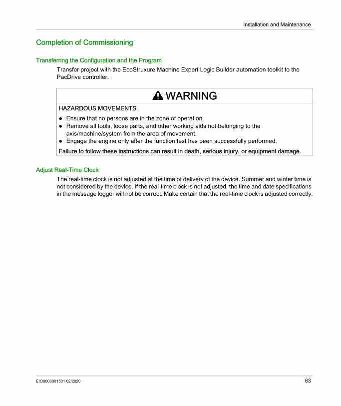
Completion of Commissioning
Transferring the Configuration and the ProgramTransfer project with the EcoStruxure Machine Expert Logic Builder automation toolkit to the PacDrive controller.
Adjust Real-Time ClockThe real-time clock is not adjusted at the time of delivery of the device. Summer and winter time is not considered by the device. If the real-time clock is not adjusted, the time and date specifications in the message logger will not be correct. Make certain that the real-time clock is adjusted correctly.
WARNINGHAZARDOUS MOVEMENTS Ensure that no persons are in the zone of operation. Remove all tools, loose parts, and other working aids not belonging to the
axis/machine/system from the area of movement. Engage the engine only after the function test has been successfully performed.Failure to follow these instructions can result in death, serious injury, or equipment damage.
EIO0000001501 02/2020 63
Installation and Maintenance
Performing the Function Test
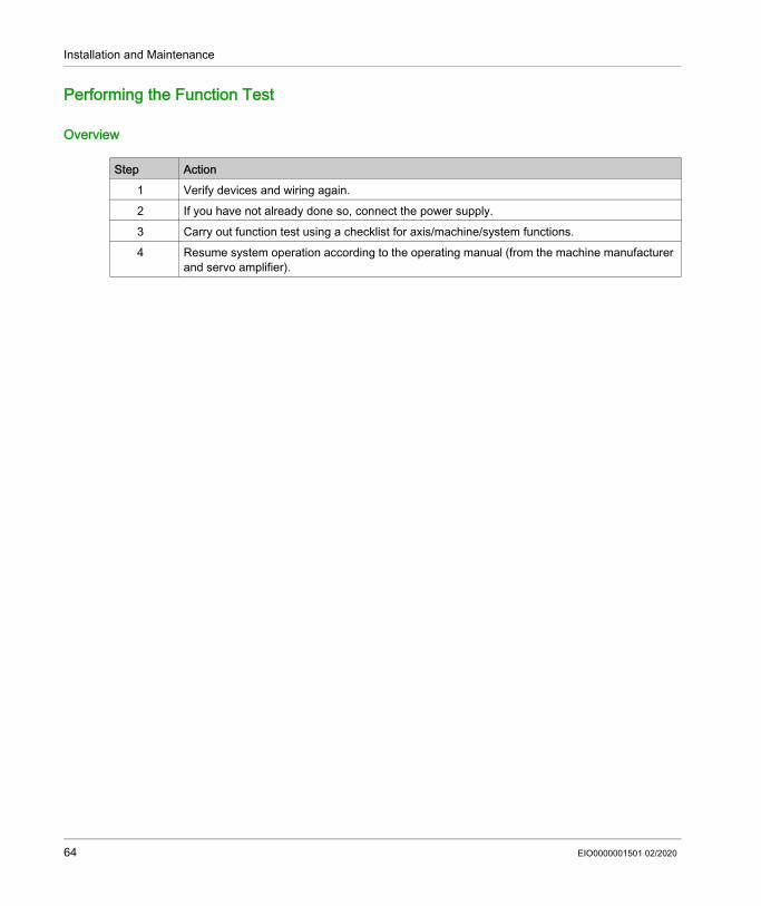
Overview
Step Action1 Verify devices and wiring again.2 If you have not already done so, connect the power supply.3 Carry out function test using a checklist for axis/machine/system functions.4 Resume system operation according to the operating manual (from the machine manufacturer
and servo amplifier).
64 EIO0000001501 02/2020

Installation and Maintenance
Maintenance, Repair, Cleaning, Replacement Equipment Inventory
Section 4.2Maintenance, Repair, Cleaning, Replacement Equipment Inventory
What Is in This Section?This section contains the following topics:
Topic PagePrerequisites for Maintenance, Repair, and Cleaning 66Repair 68Cleaning 69Battery, Real-Time Clock 70Replacement Equipment Inventory 71
EIO0000001501 02/2020 65

Installation and Maintenance
Prerequisites for Maintenance, Repair, and Cleaning
IntroductionObserve the following instructions before carrying out maintenance on the controller.
De-Energize the System
DANGERELECTRIC SHOCK, EXPLOSION, OR ARC FLASH Disconnect all power from all equipment including connected devices prior to removing any
covers or doors, or installing or removing any accessories, hardware, cables, or wires. Place a "Do Not Turn On" or equivalent hazard label on all power switches and lock them in
the non-energized position. Wait 15 minutes to allow the residual energy of the DC bus capacitors to discharge. Measure the voltage on the DC bus with a properly rated voltage sensing device and verify
that the voltage is less than 42.4 Vdc. Do not assume that the DC bus is voltage-free when the DC bus LED is off. Block the motor shaft to prevent rotation prior to performing any type of work on the drive
system. Do not create a short-circuit across the DC bus terminals or the DC bus capacitors. Replace and secure all covers, accessories, hardware, cables, and wires and confirm that a
proper ground connection exists before applying power to the unit. Use only the specified voltage when operating this equipment and any associated products.Failure to follow these instructions will result in death or serious injury.
66 EIO0000001501 02/2020
Installation and Maintenance
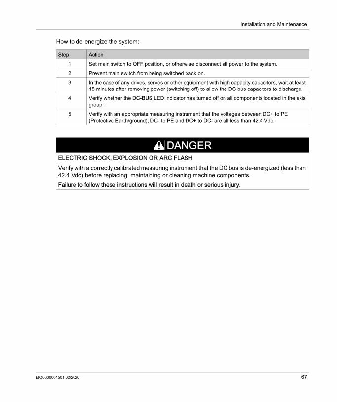
How to de-energize the system:
Step Action1 Set main switch to OFF position, or otherwise disconnect all power to the system.2 Prevent main switch from being switched back on.3 In the case of any drives, servos or other equipment with high capacity capacitors, wait at least
15 minutes after removing power (switching off) to allow the DC bus capacitors to discharge.4 Verify whether the DC-BUS LED indicator has turned off on all components located in the axis
group.5 Verify with an appropriate measuring instrument that the voltages between DC+ to PE
(Protective Earth/ground), DC- to PE and DC+ to DC- are all less than 42.4 Vdc.
DANGERELECTRIC SHOCK, EXPLOSION OR ARC FLASHVerify with a correctly calibrated measuring instrument that the DC bus is de-energized (less than 42.4 Vdc) before replacing, maintaining or cleaning machine components.Failure to follow these instructions will result in death or serious injury.
EIO0000001501 02/2020 67

Installation and Maintenance
Repair
OverviewThere are no user-serviceable parts within the PacDrive LMC Eco controller. Either replace the controller or contact your local Schneider Electric service representative
68 EIO0000001501 02/2020

Installation and Maintenance
Cleaning
Cleaning the Controller
Care must be taken with cleaning products as some active agents may have deleterious effects on plastics and stainless steel welds.
For more information on the material properties of your component, refer to Mechanical and Electrical Data (see page 122).
Step Action1 De-energize the controller (see page 66).2 Remove the controller.3 Blow out the controller with dry pressurized air (maximum 1 bar (14.5 PSI)).
NOTICECORROSION CAUSED BY CLEANING AGENTS Before using a cleaning agent, carry out a compatibility test in relation to the cleaning agent
and the component affected. Do not use alkaline detergent. Do not use any chlorid-containing cleaning agents.Failure to follow these instructions can result in equipment damage.
EIO0000001501 02/2020 69

Installation and Maintenance
Battery, Real-Time Clock
OverviewThe battery must be replaced every 10 years. After this time has elapsed, the battery must be replaced. Only Schneider Electric personnel are authorized to replace the battery. The contact addresses can be found in the chapter Contact Addresses (see page 156).If the battery is getting low, then the message Empty Battery appears on the display.NOTE: When the battery is empty and the 24 Vdc mains supply is disconnected then data (retain variables and all the data on the NVRAM) is not saved anymore.NOTE: When the battery is empty, the real-time clock is set to a default value by every start and you have to set the real-time clock to the current value.
70 EIO0000001501 02/2020

Installation and Maintenance
Replacement Equipment Inventory
PresentationKeep a stock of the most important components to make certain your machine is functioning and ready for operation.Replace devices with the same hardware configuration to help ensure compatibility.Indicate the following information on the replacement equipment order: Unicode: for example, LMC101C Hardware revision: for example, RS 01This information can be found on the nameplates.For more information concerning the replacement of components, refer to Replacing Components and Cables (see page 72).NOTE: For software and hardware compatibility information, refer to Compatibility of Lexium 62 Drives and Programming Software Versions (see EcoStruxure Machine Expert Compatibility and Migration, User Guide).
EIO0000001501 02/2020 71

Installation and Maintenance
Replacing Components and Cables
Section 4.3Replacing Components and Cables
What Is in This Section?This section contains the following topics:
Topic PagePrerequisites for Replacing Components and Cables 73Device Replacement 76Fast Device Replacement (FDR) - Introduction 78Fast Device Replacement - Usage 79Fast Device Replacement - Controller Display 81Fast Device Replacement - Application 84Cable Replacement 89
72 EIO0000001501 02/2020
Installation and Maintenance
Prerequisites for Replacing Components and Cables
De-Energize the System
DANGERELECTRIC SHOCK, EXPLOSION, OR ARC FLASH Disconnect all power from all equipment including connected devices prior to removing any
covers or doors, or installing or removing any accessories, hardware, cables, or wires. Place a "Do Not Turn On" or equivalent hazard label on all power switches and lock them in
the non-energized position. Wait 15 minutes to allow the residual energy of the DC bus capacitors to discharge. Measure the voltage on the DC bus with a properly rated voltage sensing device and verify
that the voltage is less than 42.4 Vdc. Do not assume that the DC bus is voltage-free when the DC bus LED is off. Block the motor shaft to prevent rotation prior to performing any type of work on the drive
system. Do not create a short-circuit across the DC bus terminals or the DC bus capacitors. Replace and secure all covers, accessories, hardware, cables, and wires and confirm that a
proper ground connection exists before applying power to the unit. Use only the specified voltage when operating this equipment and any associated products.Failure to follow these instructions will result in death or serious injury.
EIO0000001501 02/2020 73
Installation and Maintenance
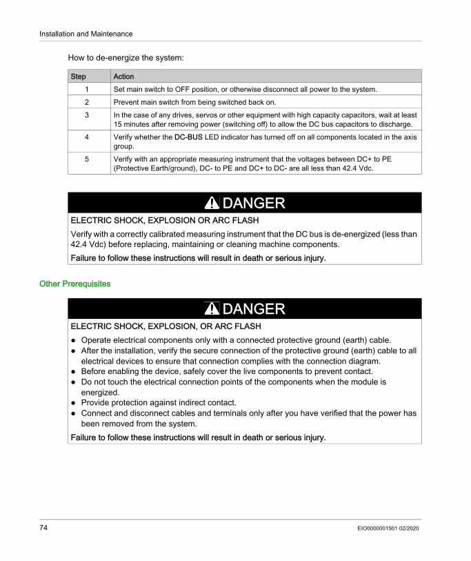
How to de-energize the system:
Other Prerequisites
Step Action1 Set main switch to OFF position, or otherwise disconnect all power to the system.2 Prevent main switch from being switched back on.3 In the case of any drives, servos or other equipment with high capacity capacitors, wait at least
15 minutes after removing power (switching off) to allow the DC bus capacitors to discharge.4 Verify whether the DC-BUS LED indicator has turned off on all components located in the axis
group.5 Verify with an appropriate measuring instrument that the voltages between DC+ to PE
(Protective Earth/ground), DC- to PE and DC+ to DC- are all less than 42.4 Vdc.
DANGERELECTRIC SHOCK, EXPLOSION OR ARC FLASHVerify with a correctly calibrated measuring instrument that the DC bus is de-energized (less than 42.4 Vdc) before replacing, maintaining or cleaning machine components.Failure to follow these instructions will result in death or serious injury.
DANGERELECTRIC SHOCK, EXPLOSION, OR ARC FLASH Operate electrical components only with a connected protective ground (earth) cable. After the installation, verify the secure connection of the protective ground (earth) cable to all
electrical devices to ensure that connection complies with the connection diagram. Before enabling the device, safely cover the live components to prevent contact. Do not touch the electrical connection points of the components when the module is
energized. Provide protection against indirect contact. Connect and disconnect cables and terminals only after you have verified that the power has
been removed from the system.Failure to follow these instructions will result in death or serious injury.
74 EIO0000001501 02/2020
Installation and Maintenance
The metal surfaces of the product may exceed 65 °C (149 °F) (for bare metal) during operation.
WARNINGUNINTENDED EQUIPMENT OPERATION Only use software and hardware components approved by Schneider Electric for use with this
equipment. Do not attempt to service this equipment outside of authorized Schneider Electric service
centers. Update your application program every time you change the physical hardware configuration.Failure to follow these instructions can result in death, serious injury, or equipment damage.
WARNINGHOT SURFACES Avoid unprotected contact with hot surfaces. Do not allow flammable or heat-sensitive parts in the immediate vicinity of hot surfaces. Verify that the heat dissipation is sufficient by performing a test run under maximum load
conditions.Failure to follow these instructions can result in death, serious injury, or equipment damage.
EIO0000001501 02/2020 75
Installation and Maintenance
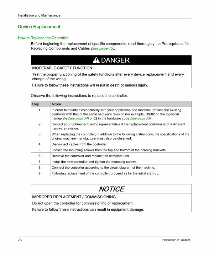
Device Replacement
How to Replace the ControllerBefore beginning the replacement of specific components, read thoroughly the Prerequisites for Replacing Components and Cables (see page 73).
Observe the following instructions to replace the controller.
DANGERINOPERABLE SAFETY FUNCTIONTest the proper functioning of the safety functions after every device replacement and every change of the wiring.Failure to follow these instructions will result in death or serious injury.
Step Action1 In order to maintain compatibility with your application and machine, replace the existing
controller with that of the same hardware revision (for example, RS:02 on the logistical nameplate (see page 34) or 02 in the hardware code (see page 93).
2 Contact your Schneider Electric representative if the replacement controller is of a different hardware revision.
3 When replacing the controller, in addition to the following instructions, the specifications of the original machine manufacturer must also be observed.
4 Disconnect cables from the controller.5 Loosen the mounting screws from the top and bottom of the housing brackets.6 Remove the controller and replace the complete unit.7 Install the new controller and tighten the mounting screws.8 Connect the controller according to the circuit diagram of the machine.9 Following replacement of the controller, proceed as for the initial start-up.
NOTICEIMPROPER REPLACEMENT / COMMISSIONINGDo not open the controller for commissioning or replacement.Failure to follow these instructions can result in equipment damage.
76 EIO0000001501 02/2020
Installation and Maintenance
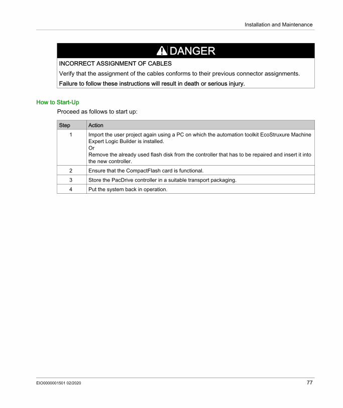
How to Start-UpProceed as follows to start up:
DANGERINCORRECT ASSIGNMENT OF CABLESVerify that the assignment of the cables conforms to their previous connector assignments.Failure to follow these instructions will result in death or serious injury.
Step Action1 Import the user project again using a PC on which the automation toolkit EcoStruxure Machine
Expert Logic Builder is installed.OrRemove the already used flash disk from the controller that has to be repaired and insert it into the new controller.
2 Ensure that the CompactFlash card is functional.3 Store the PacDrive controller in a suitable transport packaging.4 Put the system back in operation.
EIO0000001501 02/2020 77
Installation and Maintenance
Fast Device Replacement (FDR) - Introduction
IntroductionWith the help of the fast device replacement, the Lexium 62, Lexium 52 and ILM devices that are in the configuration of a EcoStruxure Machine Expert project on the controller can be replaced. There are certain parameters that have to be set in EcoStruxure Machine Expert first. Information on this can be found in the online help of EcoStruxure Machine Expert.Subsequently, certain settings on the display of the controller have to be made which are described in the following. The controller interface for FDR gives the possibility to manually access the assignment between logical devices in the controller configuration (EcoStruxure Machine Expert Logic Builder) and the physical connected devices.
78 EIO0000001501 02/2020

Installation and Maintenance
Fast Device Replacement - Usage
Error Detected During the Manual Device AssignmentIf two or more devices of the same type (or a double drive) are replaced, it is possible that an incorrect manual assignment of the logical devices to the physical connected devices is made.
Different Device TypesThe controller interface for FDR does not consider the device type of physical devices.NOTE: If the logical device type is not the same as the assigned physical device type, then a device assignment with the controller interface for FDR is possible. However, it leads to an error being detected during the Sercos phase start-up (8501 Sercos slave not found). If FDRStartMode is set to the value Phase start-up/2, then the controller interface for FDR is restarted.
Further information on the parameters can be found under Fast Device Replacement in the online help of EcoStruxure Machine Expert.
Device ReplacementIf the requirements are fulfilled (see chapter Fast Device Replacement in the EcoStruxure Machine Expert online help) and you are replacing a device, then the controller display automatically shows the start picture of the controller interface for FDR.
WARNINGUNINTENDED OPERATING STATE OF THE DEVICE Make sure that the assignment of the logical devices to the physical connected devices is
exactly the same as the device assignment before the device replacement. Before putting the machine back into service, you have to verify that the application is
addressing the physical drives correctly.Failure to follow these instructions can result in death, serious injury, or equipment damage.
EIO0000001501 02/2020 79
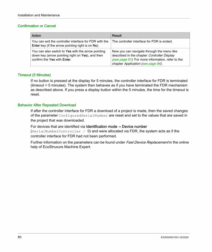
Installation and Maintenance
Confirmation or Cancel
Timeout (5 Minutes)If no button is pressed at the display for 5 minutes, the controller interface for FDR is terminated (timeout = 5 minutes). The system then behaves as if you have terminated the FDR mechanism as described above. If you press a display button within the 5 minutes, the time for the timeout is reset.
Behavior After Repeated DownloadIf after the controller interface for FDR a download of a project is made, then the saved changes of the parameter ConfiguredSerialNumber are reset and set to the values that are saved in the project that was downloaded.For devices that are identified via Identification mode → Device number (SerialNumberController / 0) and were allocated via FDR, the system acts as if the controller interface for FDR had not been performed.Further information on the parameters can be found under Fast Device Replacement in the online help of EcoStruxure Machine Expert.
Action ResultYou can exit the controller interface for FDR with the Enter key (if the arrow pointing right is on No).
The controller interface for FDR is ended.
You can also switch to Yes with the arrow pointing down key (arrow pointing right on Yes), and then confirm the Yes with Enter.
Now you can navigate through the menu like described in the chapter Controller Display (see page 81). For more information, refer to the chapter Application (see page 84).
80 EIO0000001501 02/2020

Installation and Maintenance
Fast Device Replacement - Controller Display
OverviewWhen the controller interface for FDR is active, the controller display shows the corresponding menu.The following describes the menu in general. For more information, refer to the section Application (see page 84).
General Menu Description
In the following example, FDR SNRC stands for addressing a device via the device serial number. Instead of FDR SNRC, the FDR ATYP (for application type) or FDR SADR (for Sercos address) can also be used.
Arrow / Key DescriptionIf up/down arrows are displayed at the right menu edge, you can scroll up and down using these arrow keys. Scrolling starts only after the right arrow is displayed at the lower or upper menu edge. If the right arrow is displayed in a line in between, you can move it using the up/down arrow keys
– The command that is in the line that is marked with the arrow pointing right can be confirmed/executed with the Enter key.
–
EIO0000001501 02/2020 81
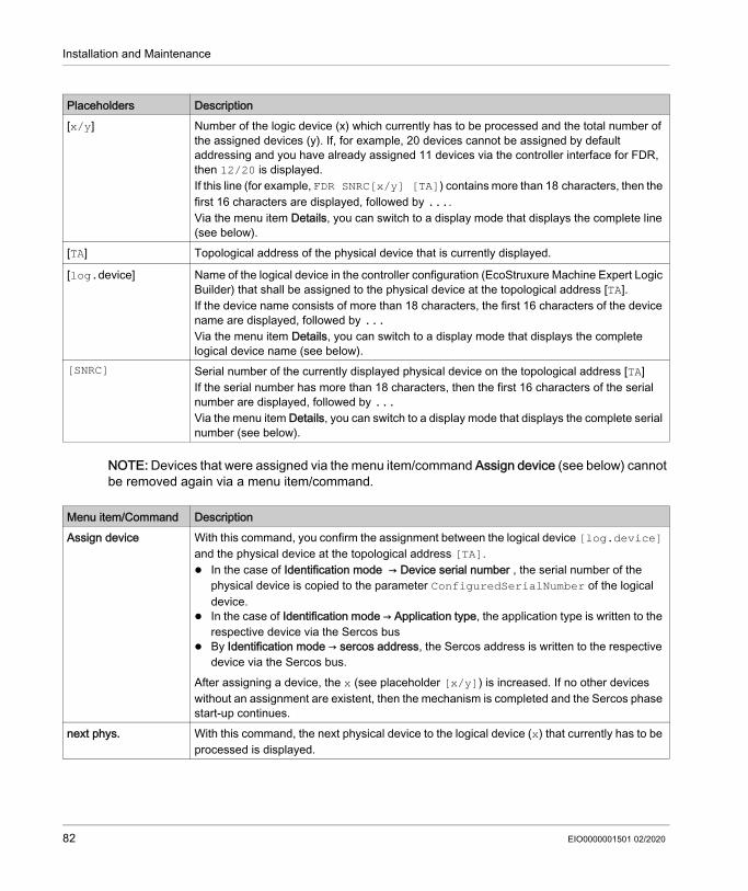
Installation and Maintenance
NOTE: Devices that were assigned via the menu item/command Assign device (see below) cannot be removed again via a menu item/command.
Placeholders Description[x/y] Number of the logic device (x) which currently has to be processed and the total number of
the assigned devices (y). If, for example, 20 devices cannot be assigned by default addressing and you have already assigned 11 devices via the controller interface for FDR, then 12/20 is displayed.If this line (for example, FDR SNRC[x/y] [TA]) contains more than 18 characters, then the first 16 characters are displayed, followed by ....Via the menu item Details, you can switch to a display mode that displays the complete line (see below).
[TA] Topological address of the physical device that is currently displayed.
[log.device] Name of the logical device in the controller configuration (EcoStruxure Machine Expert Logic Builder) that shall be assigned to the physical device at the topological address [TA].If the device name consists of more than 18 characters, the first 16 characters of the device name are displayed, followed by ...Via the menu item Details, you can switch to a display mode that displays the complete logical device name (see below).
[SNRC] Serial number of the currently displayed physical device on the topological address [TA]If the serial number has more than 18 characters, then the first 16 characters of the serial number are displayed, followed by ...Via the menu item Details, you can switch to a display mode that displays the complete serial number (see below).
Menu item/Command DescriptionAssign device With this command, you confirm the assignment between the logical device [log.device]
and the physical device at the topological address [TA]. In the case of Identification mode → Device serial number , the serial number of the
physical device is copied to the parameter ConfiguredSerialNumber of the logical device.
In the case of Identification mode → Application type, the application type is written to the respective device via the Sercos bus
By Identification mode → sercos address, the Sercos address is written to the respective device via the Sercos bus.
After assigning a device, the x (see placeholder [x/y]) is increased. If no other devices without an assignment are existent, then the mechanism is completed and the Sercos phase start-up continues.
next phys. With this command, the next physical device to the logical device (x) that currently has to be processed is displayed.
82 EIO0000001501 02/2020

Installation and Maintenance
Further information on the parameters can be found under Fast Device Replacement in the online help of EcoStruxure Machine Expert.
Details With this command, it is possible to switch to a display mode that displays the complete lines (multi-line).This is helpful if in the standard view lines cannot be displayed completely (see above).For a logical device, a maximum of 40 characters can be displayed
back With this command, it is possible to switch back to the standard view (maximum 16 characters followed by ... are displayed).
Exit FDR With this command, the controller interface for FDR is canceled.The cancelation has to be confirmed once again (Really exit? → Exit FDR).
Menu item/Command Description
EIO0000001501 02/2020 83

Installation and Maintenance
Fast Device Replacement - Application
Starting ConditionsThe following example shows a typical application for the controller interface for FDR. For the displayed example, the following applies: All the devices are operational. The Sercos bus is started up. For all the devices, the Device addressing via the Identification mode → Device serial number
was made (parameter SerialNumberController / 0). The parameter FDRConfirmationMode of the controller was set to the value
by Display / 0.
Further information on the parameters can be found under Fast Device Replacement in the online help of EcoStruxure Machine Expert.
84 EIO0000001501 02/2020

Installation and Maintenance
Device ReplacementThe following devices have to be replaced because of maintenance: The device at the topology address 2 (TA:2) with the logical device name DEV_02 and the serial
number SNRC phy: xxx-02 has to be replaced by the new device that has the serial number SNRC phy: xxx-15.
The device at the topology address 5 (TA:5) with the logical device name DEV_05 and the serial number SNRC phy xxx-05 has to be replaced by the new device that has the serial number SNRC phy xxx-16.
After the Device Replacement
After the physical replacement of the devices the machine has to be restarted again. In order for the controller interface for FDR to be started, the parameter FDRStartMode has to be set to Start/1 or Phase start-up/2 and the parameter FDRConfirmationMode to by display / 0.
EIO0000001501 02/2020 85

Installation and Maintenance
Now the controller interface for FDR has to find the correct assignment of the two logical devices DEV_02 and DEV_05 to the new physically connected devices at topology address 2 and 5.
Further information on the parameters can be found under Fast Device Replacement in the online help of EcoStruxure Machine Expert.
ProcessThe controller interface for FDR verifies all the logical devices one after another which would trigger the diagnostic message 8501 Sercos slave not found during the Sercos phase start-up. Afterwards, to the respective logical device all the physical devices are checked until one device is acknowledged.Due to space constraints, the sequence for device 1 and device 2 is displayed one beneath the other.
86 EIO0000001501 02/2020

Installation and Maintenance
EIO0000001501 02/2020 87
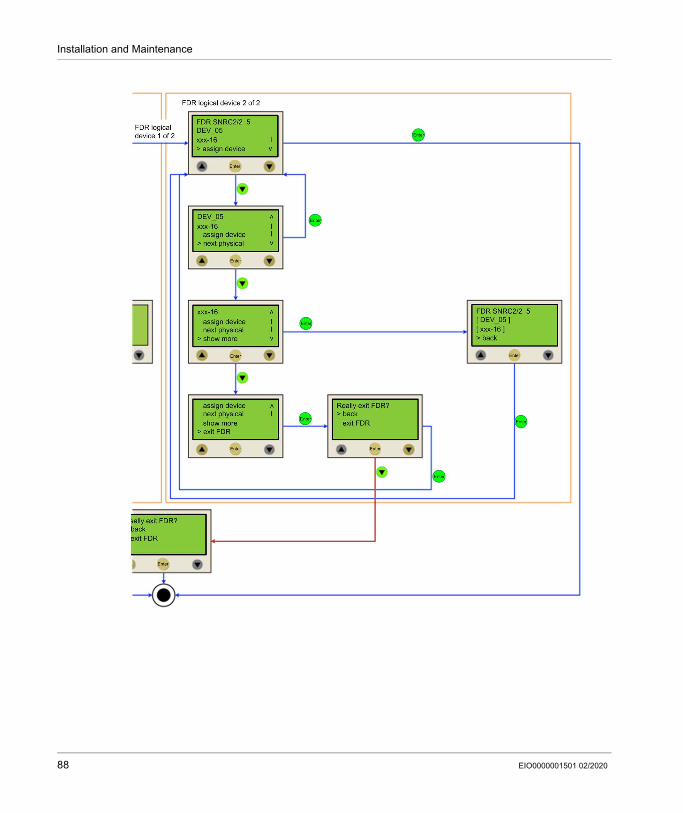
Installation and Maintenance
88 EIO0000001501 02/2020

Installation and Maintenance
Cable Replacement
IntroductionNOTE: In addition to the following instructions, you must observe the specifications of the machine manufacturer when replacing the cables.
De-Energize the System
DANGERELECTRIC SHOCK, EXPLOSION, OR ARC FLASH Disconnect all power from all equipment including connected devices prior to removing any
covers or doors, or installing or removing any accessories, hardware, cables, or wires. Place a "Do Not Turn On" or equivalent hazard label on all power switches and lock them in
the non-energized position. Wait 15 minutes to allow the residual energy of the DC bus capacitors to discharge. Measure the voltage on the DC bus with a properly rated voltage sensing device and verify
that the voltage is less than 42.4 Vdc. Do not assume that the DC bus is voltage-free when the DC bus LED is off. Block the motor shaft to prevent rotation prior to performing any type of work on the drive
system. Do not create a short-circuit across the DC bus terminals or the DC bus capacitors. Replace and secure all covers, accessories, hardware, cables, and wires and confirm that a
proper ground connection exists before applying power to the unit. Use only the specified voltage when operating this equipment and any associated products.Failure to follow these instructions will result in death or serious injury.
EIO0000001501 02/2020 89

Installation and Maintenance
How to de-energize the system:
ProcedureProceed as follows for cable replacement: Be sure that the cables clearly indicate their connections before disconnecting. Replace cables with an identical type and length. Refer to any documentation from the original machine manufacturer before replacing cables. Disconnect/Attach the cable from the equipment components involved.
Step Action1 Set main switch to OFF position, or otherwise disconnect all power to the system.2 Prevent main switch from being switched back on.3 In the case of any drives, servos or other equipment with high capacity capacitors, wait at least
15 minutes after removing power (switching off) to allow the DC bus capacitors to discharge.4 Verify whether the DC-BUS LED indicator has turned off on all components located in the axis
group.5 Verify with an appropriate measuring instrument that the voltages between DC+ to PE
(Protective Earth/ground), DC- to PE and DC+ to DC- are all less than 42.4 Vdc.
DANGERELECTRIC SHOCK, EXPLOSION OR ARC FLASHVerify with a correctly calibrated measuring instrument that the DC bus is de-energized (less than 42.4 Vdc) before replacing, maintaining or cleaning machine components.Failure to follow these instructions will result in death or serious injury.
DANGERINCORRECT ASSIGNMENT OF CABLESVerify that the assignment of the cables conforms to their previous connector assignments.Failure to follow these instructions will result in death or serious injury.
90 EIO0000001501 02/2020

PacDrive Logic Motion ControllerIndicators and Control ElementsEIO0000001501 02/2020
Indicators and Control Elements
Chapter 5Indicators and Control Elements
What Is in This Chapter?This chapter contains the following topics:
Topic PageIndicators of the Controller 92Menu Navigation 97SD Card Slot 101USB Connection 105
EIO0000001501 02/2020 91
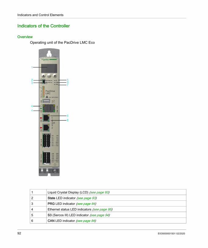
Indicators and Control Elements
Indicators of the Controller
OverviewOperating unit of the PacDrive LMC Eco
1 Liquid Crystal Display (LCD) (see page 93)2 State LED indicator (see page 93)3 PRG LED indicator (see page 94)4 Ethernet status LED indicators (see page 95)5 S3 (Sercos III) LED indicator (see page 94)6 CAN LED indicator (see page 94)
92 EIO0000001501 02/2020

Indicators and Control Elements
Liquid Crystal Display (LCD)
In addition to the LED indicators, further information about the operating status of the controller is given on the 4-line Liquid Crystal Display (LCD).
State LED IndicatorThe State LED indicator indicates whether a control voltage is applied, whether errors are detected by the controller and whether the controller performs a minimum boot.
7 TM5 LED indicator (see page 95)8 Sercos status LED indicators (see page 95)
Line 1 Controller type and firmware versionLine 2 Current IP address of the controllerLine 3 –Line 4 PFPGA version/SFPGA version/BIOS version
LED indicator color / status
Meaning
Off The control voltage (24 Vdc) is missing or too low.Green Normal operation, control voltage in normal rangeRed System error detected, error is shown on the display
Initialization active after power-onAn error is detected by the controller after initialization, for further information on the detected error, see the message logger.
Quickly flashes red The controller performs a minimal boot
EIO0000001501 02/2020 93

Indicators and Control Elements
PRG LED IndicatorThe PRG LED indicator indicates the state of the USB communication on the programming port (CN1).
NOTE: The function to establish a connection to the controller via USB is not implemented.
S3 (Sercos III) LED IndicatorThe S3 LED indicator indicates the state and the phases of the Sercos communication.
CAN LED IndicatorCAN LED indicator is a two-color light-emitting diode (LED), alternating between two states: a run state (green color) and an error state (red color). CAN LED indicator colors can be flashing (different sequences), or steady, as described below.
LED indicator color / status
Meaning
Off No USB communication on the programming port.Green USB communication detected.
LED indicator color / status
Meaning Instructions/information for the user Notes
Off No Sercos communication – –Orange The device is in a
communication phase CP0 up to and including CP3.
– SERC3.State = 0..3
Green Sercos communication in communication phase CP4 without error detected.
– SERC3.State = 4
Red Detected communication error. Reset condition: DiagQuit SERC3.State = 11
State Color display mode MeaningOff – No powerFlashing green50 ms/50 ms
The LED indicator repeatedly flashes according to the following sequence: on for 50 ms, then off for 50 ms.
Autobaud detection in progress.
Flashing green200 ms/200 ms
The LED indicator repeatedly flashes according to the following sequence: on for 200 ms, then off for 200 ms
Pre-operational state
Flashing green200 ms/1000 ms
Single flash: The LED indicator flashes according to the following sequence: on for 200 ms, then off for 1000 ms
Stopped state
Green Steady Operating state.
94 EIO0000001501 02/2020

Indicators and Control Elements
TM5 LED IndicatorNOTE: The TM5 LED indicator and TM5 connector CN10 are not fimplemented.
Ethernet Status LED IndicatorsThe Ethernet connector has two LED indicators. One LED indicator is green, the other is yellow.
Sercos Status LED indicatorsEach Sercos connector has two LED indicators. One LED indicator is green, the other is yellow.
Flashing red Single flash: The LED indicator flashes according to the following sequence: on for 200 ms, then off for 1000 ms
Limit to trigger diagnostic message reached
Double flash: The LED indicator flashes according to the following sequence: on for 200 ms, off for 200 ms, on for 200 ms, then off for 1000 ms
A cyclic checking has detected an error
Triple flash: The LED indicator flashes according to the following sequence: on for 200 ms, off for 200 ms, on for 200 ms, off for 200 ms, on for 200 ms, then off for 1000 ms
Synchronization error detected. no Sync message received within the configured communication cycle timeout
Red Steady Bus off
State Color display mode Meaning
LED indicator State MeaningGreen On Connection establishedGreen Flashing Data trafficGreen Off No connection, for example, no cable connected, or connected
device has no powerYellow On 1 GBit/s connectionYellow On 100 MBit/s connectionYellow Off 10 MBit/s connection
LED indicator State MeaningYellow On Connection established
Off No cable connected or connected device has no power.Green On Active network traffic
Off No active network traffic
EIO0000001501 02/2020 95

Indicators and Control Elements
Protocol-specific Status LED IndicatorsLED indicators PROFINET device
LED indicator Color State MeaningSF Name in the device drawing: COM 0
red / green LED indicatorRed On Watchdog timeout
Detected error on a channel.
Detected system error.
Red Flashes at 2 Hz. (for 3 s) DCP signal service is initiated via the bus.
Off Off No error.BF Name in the device drawing: COM 1
red / green LED indicatorRed On No configration
Low speed physical link No physical link
Red Flashes at 2 Hz. No data exchangeOff Off No error
LINK/RJ45 Ch0 & Ch1 green LED indicatorGreen On A connection to Ethernet
exists.Off Off The device has no
connection to Ethernet.RX/TX/RJ45 Ch0 & Ch1 yellow LED indicator
Yellow Flashes The device sends/receives Ethernet frames.
96 EIO0000001501 02/2020

Indicators and Control Elements
Menu Navigation
Menu ButtonsThree menu buttons are located on the front side of the controller. With these menu buttons, the user can open and navigate through the menu.
1 Up arrow button2 Enter button3 Down arrow button
Functions of the Menu ButtonsUnder the Liquid Crystal Display (LCD), three menu buttons are located through which the user can open and navigate in the menu. The menu buttons feature the following functions:
Buttons Function
First and then simultaneously
Access of the menu
Cursor up
Cursor down
Open menu item
First and then simultaneously
One level up in the menu
EIO0000001501 02/2020 97

Indicators and Control Elements
If an up or down arrow is displayed on the right display edge, this indicates that the current menu
has more lines than can be shown on the display. In this case, you can use the arrow buttons
and to scroll up or down.
Menu Navigation
98 EIO0000001501 02/2020

Indicators and Control Elements
Description of the Menu NavigationThe submenu Versions provides an overview of all the software and hardware versions installed on the controller.
In the submenu HCode/SerialNo. a serial number and the hardware code are displayed. The serial number is a unique number which is used to identify the controller. The hardware code indicates the hardware revision.
In the submenu IP address, the IP address, the subnet mask, and the gateway are displayed.
The MAC address is specified in the submenu MAC address. The MAC address is a clear address of the device to identify the device in the network.
Item DescriptionFW Currently used firmware version.PFPGA Version of the PacDrive FPGA softwareSFPGA Version of the System FPGA softwareBIOS BIOS version
Item DescriptionSerial number Controller serial numberHardware code Hardware code of the controller(1)
(1) The first two digits of the hardware code indicate the hardware revision (for example, 02). The hardware revision is also indicated on the logistical nameplate (see page 34) (for example, RS:02). In order to maintain compatibility with your application and machine, replace the existing controller with that of the same hardware code.
Item DescriptionIP IP address of the controllerMASK Subnet maskGW Gateway
Item DescriptionMAC address MAC address
EIO0000001501 02/2020 99

Indicators and Control Elements
In the submenu Inputs, the user can prompt the logic state of each input. The digital inputs correspond to the standard IEC61131-2 type 1. Touchprobes and fast inputs have a resolution of 10 µs. Fast inputs can be used to trigger an interrupt.
In the submenu Outputs, the user can prompt the logic state of each output.
In the submenu DiagMessage, the diagnostic class, the diagnostic code, and the diagnostic text are displayed. The system assigns each diagnostic message a specific diagnostic class when enabled. The diagnostic code is a code that encrypts a certain diagnostic. In the diagnostic text, a diagnostic is described in detail.
In the submenu Select language, the user can choose the display language.
Item DescriptionDI Digital inputADI Advanced digital input
Item DescriptionDQ Outputs
Item DescriptionA: A: Diagnostic classBBB: BBBB: Diagnostic codeC...C C...C: Diagnostic text
Item DescriptionSelect language:German Display language is German.English Display language is English.
100 EIO0000001501 02/2020
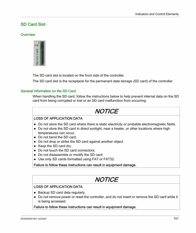
Indicators and Control Elements
SD Card Slot
Overview
The SD card slot is located on the front side of the controller.The SD card slot is the receptacle for the permanent data storage (SD card) of the controller.
General Information on the SD CardWhen handling the SD card, follow the instructions below to help prevent internal data on the SD card from being corrupted or lost or an SD card malfunction from occurring:
NOTICELOSS OF APPLICATION DATA Do not store the SD card where there is static electricity or probable electromagnetic fields. Do not store the SD card in direct sunlight, near a heater, or other locations where high
temperatures can occur. Do not bend the SD card. Do not drop or strike the SD card against another object. Keep the SD card dry. Do not touch the SD card connectors. Do not disassemble or modify the SD card. Use only SD cards formatted using FAT or FAT32.Failure to follow these instructions can result in equipment damage.
NOTICELOSS OF APPLICATION DATA Backup SD card data regularly. Do not remove power or reset the controller, and do not insert or remove the SD card while it
is being accessed.Failure to follow these instructions can result in equipment damage.
EIO0000001501 02/2020 101
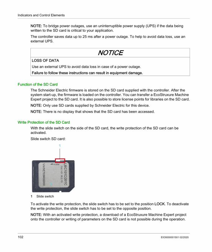
Indicators and Control Elements
NOTE: To bridge power outages, use an uninterruptible power supply (UPS) if the data being written to the SD card is critical to your application.The controller saves data up to 25 ms after a power outage. To help to avoid data loss, use an external UPS.
Function of the SD CardThe Schneider Electric firmware is stored on the SD card supplied with the controller. After the system start-up, the firmware is loaded on the controller. You can transfer a EcoStruxure Machine Expert project to the SD card. It is also possible to store license points for libraries on the SD card.NOTE: Only use SD cards supplied by Schneider Electric for this device. NOTE: There is no display that shows that the SD card has been accessed.
Write Protection of the SD CardWith the slide switch on the side of the SD card, the write protection of the SD card can be activated.Slide switch SD card:
1 Slide switch
To activate the write protection, the slide switch has to be set to the position LOCK. To deactivate the write protection, the slide switch has to be set to the opposite position.NOTE: With an activated write protection, a download of a EcoStruxure Machine Expert project onto the controller or writing of parameters on the SD card is not possible during the operation.
NOTICELOSS OF DATAUse an external UPS to avoid data loss in case of a power outage.Failure to follow these instructions can result in equipment damage.
102 EIO0000001501 02/2020
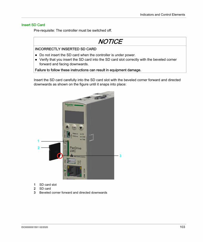
Indicators and Control Elements
Insert SD CardPre-requisite: The controller must be switched off.
Insert the SD card carefully into the SD card slot with the beveled corner forward and directed downwards as shown on the figure until it snaps into place:
1 SD card slot2 SD card3 Beveled corner forward and directed downwards
NOTICEINCORRECTLY INSERTED SD CARD Do not insert the SD card when the controller is under power. Verify that you insert the SD card into the SD card slot correctly with the beveled corner
forward and facing downwards.Failure to follow these instructions can result in equipment damage.
EIO0000001501 02/2020 103

Indicators and Control Elements
Remove SD CardPre-requisite: The controller must be switched off.
Step Action1 Push the SD card slightly inside until it disengages.2 Remove the SD card from the SD card slot.
NOTICEINCORRECTLY REMOVED SD CARDDo not remove the SD card when the controller is under power.Failure to follow these instructions can result in equipment damage.
104 EIO0000001501 02/2020

Indicators and Control Elements
USB Connection
OverviewIt is possible to connect storage media for the extension of the memory to the connection CN2 (USB-A). Only a storage medium and no USB-hubs may be connected to the connectionNOTE: The storage medium must only be inserted if the firmware controller is started up. Otherwise the firmware of the controller does not start up.
EIO0000001501 02/2020 105

Indicators and Control Elements
106 EIO0000001501 02/2020

PacDrive Logic Motion ControllerIntegrated Communication PortsEIO0000001501 02/2020
Integrated Communication Ports
Chapter 6Integrated Communication Ports
What Is in This Chapter?This chapter contains the following topics:
Topic PageElectrical Connections Overview 108Connection Details Controller 112
EIO0000001501 02/2020 107

Integrated Communication Ports
Electrical Connections Overview
Front PanelConnection overview front panel
Connection Meaning Connection cross-section [mm2] / [AWG]
Tightening torque [Nm] / [lbf in]
CN1 Prog port (USB mini-b), not active – –CN2 USB A – –CN3 Ethernet connection – –CN4 Serial link (COM) – –
108 EIO0000001501 02/2020

Integrated Communication Ports
Ferrule dimensions for CN7, CN8, CN9, CN10:
CN5 Sercos, port 1 – –CN6 Sercos, port 2 – –CN7 Digital inputs 0.2…1.5 / 24...16 –CN8 Digital outputs 0.2…1.5 / 24...16 –
Ferrules without insulating collar (according to DIN 46228-1)Cross-section [mm²] / [AWG] Length [mm] / [in.]0.25 / 24 7 / 0.280.34 / 22 7 / 0.280.5 / 20 8...10 / 0.31...0.400.75 / 20 8...10 / 0.31...0.401.00 / 18 8...10 / 0.31...0.401.50 / 16 10 / 0.40
Ferrules with insulating collar (according to DIN 46228-4)Cross-section [mm²] / [AWG] Length [mm] / [in.]0.14 / 26 8 / 0.310.25 / 24 8 / 0.310.34 / 22 8 / 0.310.5 / 20 8...10 / 0.31...0.400.75 / 20 10 / 0.40
Connection Meaning Connection cross-section [mm2] / [AWG]
Tightening torque [Nm] / [lbf in]
EIO0000001501 02/2020 109

Integrated Communication Ports
Top SideConnection overview top side
Connection Meaning Connection cross-section [mm2] / [AWG]
Tightening torque [Nm] / [lbf in]
CN9 24 Vdc 0.2…1.5 / 24...16 –CN10 TM5 (not active) – –CN11 CAN – 0.4 Nm / 3.54 lbf inCN12 Master encoder input – –
110 EIO0000001501 02/2020
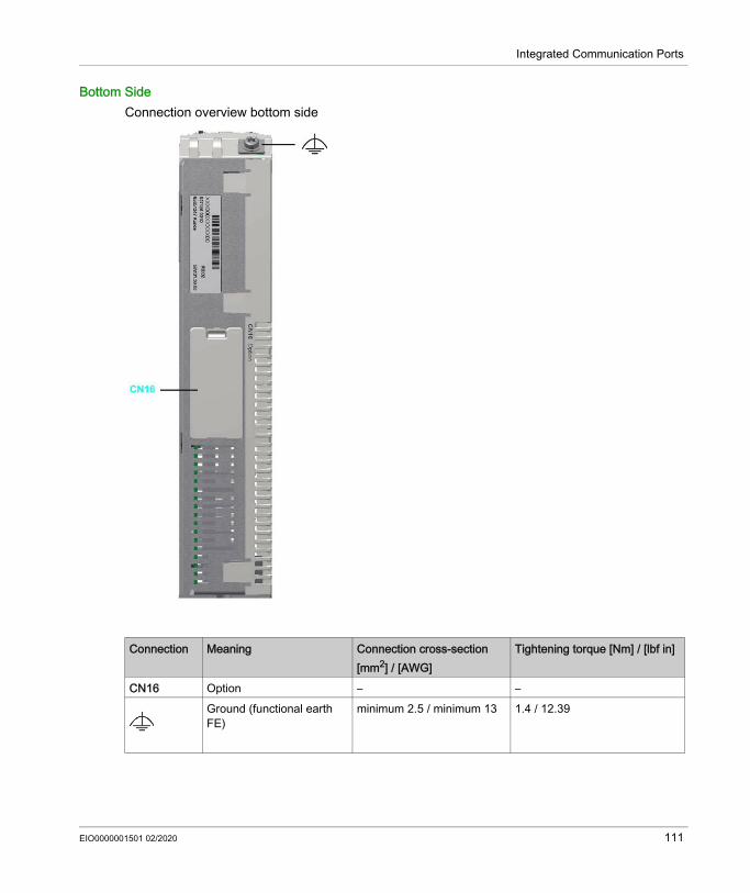
Integrated Communication Ports
Bottom SideConnection overview bottom side
Connection Meaning Connection cross-section [mm2] / [AWG]
Tightening torque [Nm] / [lbf in]
CN16 Option – –Ground (functional earth FE)
minimum 2.5 / minimum 13 1.4 / 12.39
EIO0000001501 02/2020 111

Integrated Communication Ports
Connection Details Controller
CN1 - Prog Port (USB mini-B)NOTE: Prog port (USB mini-B) is not active.
CN2 - USB-A
Connection CN2 USB - A
CN3 - Ethernet
Connection CN3
Pin Designation Meaning1 VBUS / +5V –2 D- / Data- Data line -3 D+ / Data+ Data line +4 GND / Ground –
Pin Designation1 D1 + (Tx+)2 D1- (Tx-)3 D2+ (Rx+)4 D3+5 D3-6 D2- (Rx-)7 D4+8 D4-
112 EIO0000001501 02/2020
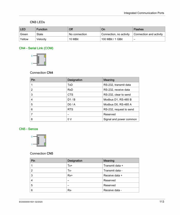
Integrated Communication Ports
CN3 LEDs
CN4 - Serial Link (COM)
Connection CN4
CN5 - Sercos
Connection CN5
LED Function Off On FlashesGreen State No connection Connection, no activity Connection and activityYellow Velocity 10 MBit 100 MBit / 1 GBit –
Pin Designation Meaning1 TxD RS-232, transmit data2 RxD RS-232, receive data3 CTS RS-232, clear to send4 D1 / B Modbus D1, RS-485 B5 D0 / A Modbus D0, RS-485 A6 RTS RS-232, request to send7 – Reserved8 0 V Signal and power common
Pin Designation Meaning1 Tx+ Transmit data +2 Tx- Transmit data -3 Rx+ Receive data +4 – Reserved5 – Reserved6 Rx- Receive data -
EIO0000001501 02/2020 113

Integrated Communication Ports
The Sercos LEDs indicate the state of the Sercos connection:
CN6 - Sercos
Connection CN6
The Sercos LEDs indicate the state of theSercos connection:
7 – Reserved8 – Reserved
LED OnGreen ActivityYellow Connection
Pin Designation Meaning
Pin Designation Meaning1 Tx+ Transmit data +2 Tx- Transmit data -3 Rx+ Receive data +4 – Reserved5 – Reserved6 Rx- Receive data -7 – Reserved8 – Reserved
LED OnGreen ActivityYellow Connection
114 EIO0000001501 02/2020

Integrated Communication Ports
CN7 - Digital Input
Connection CN7
CN8 - Digital Output
Pin Designation Meaning1 DI0 Digital inputs2 DI13 DI24 DI35 DI46 DI57 0V1 Reference potential
DI0...DI118 DI6 Digital inputs9 DI710 DI8 (FI_0) Expanded inputs11 DI9 (FI_1)12 DI10 (FI_2)13 DI11 (FI_3)14 0V2 Reference potential
DI0...DI11
EIO0000001501 02/2020 115
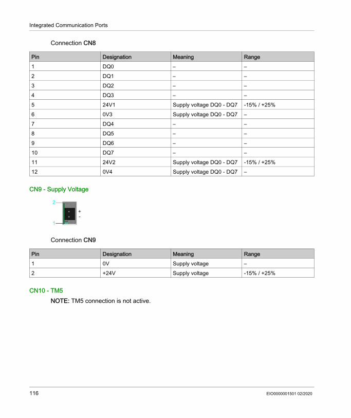
Integrated Communication Ports
Connection CN8
CN9 - Supply Voltage
Connection CN9
CN10 - TM5NOTE: TM5 connection is not active.
Pin Designation Meaning Range1 DQ0 – –2 DQ1 – –3 DQ2 – –4 DQ3 – –5 24V1 Supply voltage DQ0 - DQ7 -15% / +25%6 0V3 Supply voltage DQ0 - DQ7 –7 DQ4 – –8 DQ5 – –9 DQ6 – –10 DQ7 – –11 24V2 Supply voltage DQ0 - DQ7 -15% / +25%12 0V4 Supply voltage DQ0 - DQ7 –
Pin Designation Meaning Range1 0V Supply voltage –2 +24V Supply voltage -15% / +25%
116 EIO0000001501 02/2020
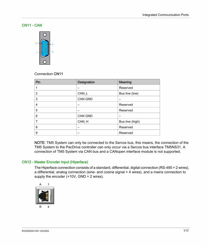
Integrated Communication Ports
CN11 - CAN
Connection CN11
NOTE: TM5 System can only be connected to the Sercos bus, this means, the connection of the TM5 System to the PacDrive controller can only occur via a Sercos bus interface TM5NS31. A connection of TM5 System via CAN bus and a CANopen interface module is not supported.
CN12 - Master Encoder Input (Hiperface)The Hiperface connection consists of a standard, differential, digital connection (RS-485 = 2 wires), a differential, analog connection (sine- and cosine signal = 4 wires), and a mains connection to supply the encoder (+10V, GND = 2 wires).
Pin Designation Meaning1 – Reserved2 CAN_L Bus line (low)3 CAN GND –4 – Reserved5 – Reserved6 CAN GND –7 CAN_H Bus line (high)8 – Reserved9 – Reserved
EIO0000001501 02/2020 117
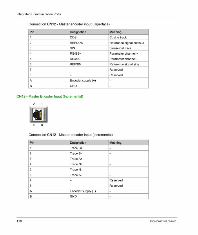
Integrated Communication Ports
Connection CN12 - Master encoder input (Hiperface)
CN12 - Master Encoder Input (Incremental)
Connection CN12 - Master encoder input (incremental)
Pin Designation Meaning1 COS Cosine track2 REFCOS Reference signal cosinus3 SIN Sinusoidal trace4 RS485+ Parameter channel +5 RS485- Parameter channel -6 REFSIN Reference signal sine7 – Reserved8 – ReservedA Encoder supply (+) –B GND –
Pin Designation Meaning1 Trace B+ –2 Trace B- –3 Trace A+ –4 Trace N+ –5 Trace N- –6 Trace A- –7 – Reserved8 – ReservedA Encoder supply (+) –B GND –
118 EIO0000001501 02/2020
PacDrive Logic Motion ControllerTechnical DataEIO0000001501 02/2020
Technical Data
Chapter 7Technical Data
What Is in This Chapter?This chapter contains the following topics:
Topic PageAmbient Conditions 120Standards and Regulations 121Mechanical and Electrical Data 122Dimensions 125
EIO0000001501 02/2020 119

Technical Data
Ambient Conditions
Ambient Conditions for Control Cabinet Devices:
Procedure Parameter Value BasisOperation Class 3K3 IEC/EN 60721-3-3
Degree of protection housing IP 20Pollution degree 2 (according to IEC 61131-2,
UL508)Ambient temperature +5...+55 °C / +41...+131 °FCondensation NoIcing NoRelative humidity 5%...95%Installation height 0...2000 m (0...6561 ft)(1)
No derating
Installation height 2000...3000 m (6561...9842 ft)(1)
40 °C / 104 °F maximum ambient temperature
Class 3M4Shock 100 m/s2
Vibration 10 m/s2
Transport Class 2K3 IEC/EN 60721-3-2Ambient temperature -25...+70 °C / -13...+158 °FCondensation NoIcing NoRelative humidity 5%...95%Maximum altitude of transport 10000 m (32808 ft)Class 2M2Shock 300 m/s2
Vibration 15 m/s2
Long-term storage in transport packaging
Class 1K4 IEC/EN 60721-3-1Ambient temperature -25...+55 °C / -13...+131 °FCondensation NoIcing NoRelative humidity 5%...95%
(1) The installation height is defined as height above sea level.
120 EIO0000001501 02/2020
Technical Data
Standards and Regulations
OverviewDeclarations and certifications
CE EMC Directive 2014/30/EU EN 61131-2:2007 (Zone B)
cULus UL 508: Industrial Control EquipmentCSA 22.2 No. 142: Process Control Equipment
CSA Process Control Equipment CSA 22.2 No. 142
China RoHS Marking for the Restricted Use of Hazardous Substances in Electronic and Electrical Products SJ/T 11364
EIO0000001501 02/2020 121

Technical Data
Mechanical and Electrical Data
Technical Data PacDrive LMC Eco
Category Parameter ValueProduct configuration Type code LMC
100CLMC 101C
LMC 106C
LMC 201C
LMC 212C
LMC 216C
Configuration Processor CPU Intel Atom 1.66 GHz512 KB L2 cache
Random access memory ≥512 MB RAMNV RAM 128 KBBattery for NVRAM and RTC Yes (internal, data retention > 10 years)SD card At least 512 MB (accessible from the outside)Control buttons 3On/off button NoReset button NoCooling PassiveReal Time Clock (RTC) Yes (deviation maximum ± 1 s in 24 h)Maximum number of drives (servo axes)
0 4 6 8 12 16
Operating system Real-time operating system VxWorks and SEA Automation kernelDiagnostics Watchdog Yes (configurable output)
Diagnostic display Liquid Crystal Display (LCD) 128 x 64 (with background lighting)
Status LED's State / CAN / TM5 / S3 / PRGIntegrated data logger for diagnostic messages
Yes
Integrated trace recorder (software oscilloscope)
Yes
Bus connections Integrated automation bus Sercos (master)Integrated additional fieldbus CAN (master/slave)TM5 bus Expandability for future interfaces, under preparation
122 EIO0000001501 02/2020

Technical Data
Communication / interfaces
Serial interfaces 1 x COM: RS-232 / RS-485 (RJ45)Modbus Yes (RJ45)Network connection 1 x Ethernet 10/100/1000 Base-T (RJ45)USB connection 1 x USB-A (host for storage medium)
1 x USB mini-B (client for engineering), not activeOptional slot for another fieldbus 1 x communication module realtime Ethernet or
1 x communication module PROFIBUS DPProgramming- languages IEC 61131-3
– Continuous function chart (CFC)Function block diagram (FBD)Instruction list (IL)Structured text (ST)Ladder diagram (LD)Sequential function chart (SFC)
Touchprobe + fast inputs (Interrupt)
Number 4 (TP & fast inputs) (IEC61131-2 type1)Range UIN 0 voltage -3...5 Vdc
Range UIN 1 voltage 15...30 Vdc
Input current IIN = 4 mA at UIN = 24 Vdc
Polarized YesInput filter DI8...DI11 100 µs - 4.29 sTouchprobe resolution DI8 to DI11
10 µs at a Sercos cycle time of 1, 2, 4 ms
Digital inputs Number 8 (IEC61131-2 type1)Range UIN 0 voltage -3...5 Vdc
Range UIN 1 voltage 15...30 Vdc
Input current IIN = 4 mA at UIN = 24 Vdc
Polarized YesInput filter DI0...DI7 100 µs - 4.29 s
Category Parameter ValueProduct configuration Type code LMC
100CLMC 101C
LMC 106C
LMC 201C
LMC 212C
LMC 216C
EIO0000001501 02/2020 123

Technical Data
Digital outputs Number 8 (IEC61131-2 type1)Output voltage (+UL-3 V) < UOUT < +UL
Rated current Ie = 500 mA rated per output and 2 A maximum for all outputs at once (for example, 8 outputs with 250 mA)
Inrush current Iemax < 2 A for 1 s
Leakage current with 0 signal ≤ 0.5 mATransmission time <100 µsShort circuit protection YesOpen circuit detection YesOpenload failure detection Rload > 150 kΩ
Overload failure detection UDQ+24V - UDQx > 4.0 V
Master encoder input Hiperface® Voltage output: 10 V / 200 mA Analog channel 0.9 V...1.1 Vpp / 2.2...2.8 Voffset (maximum 250 KHz)Parameter channel Hiperface RS-485: Cable length ≤50 m (164 ft)
INC Voltage output: 5 V / 300 mA Level according to RS422 (maximum 1 MHz) Cable length ≤50 m (164 ft)
Power supply Power consumption of power supply
20.4 Vdc...30 Vdcmaximum 27 W
Inrush current maximum 10 ADimensions Dimensions of housing DxWxH (mm): 222 x 44 x 270Weight Weight (with accessory and
carton) 1.6 kg (2.2 kg) / 3.52 lbs (4.9 lbs)
Category Parameter ValueProduct configuration Type code LMC
100CLMC 101C
LMC 106C
LMC 201C
LMC 212C
LMC 216C
124 EIO0000001501 02/2020
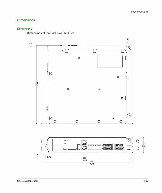
Technical Data
Dimensions
DimensionsDimensions of the PacDrive LMC Eco:
EIO0000001501 02/2020 125

Technical Data
126 EIO0000001501 02/2020
PacDrive Logic Motion ControllerOptional ModulesEIO0000001501 02/2020
Optional Modules
Chapter 8Optional Modules
What Is in This Chapter?This chapter contains the following sections:
Section Topic Page8.1 Communication Module Realtime Ethernet 1288.2 Communication Module PROFIBUS DP 145
EIO0000001501 02/2020 127

Optional Modules
Communication Module Realtime Ethernet
Section 8.1Communication Module Realtime Ethernet
What Is in This Section?This section contains the following topics:
Topic PageOverview 129Mechanical Installation 131Electrical Connections 134
128 EIO0000001501 02/2020

Optional Modules
Overview
General InformationThe communication module Realtime Ethernet is an optional module that provides a PROFINET, EtherNet/IP, or EtherCAT slave interface. Communication module Realtime Ethernet - connections
1 Ethernet channel 02 Ethernet channel 1
After installing the optional module, the controller will automatically detect the module. Then configure it by using the PLC configuration in EcoStruxure Machine Expert Logic Builder.
LED Labels of the Realtime Ethernet Communication ModuleWith the Realtime Ethernet communication modules, it is possible to use different protocols. The meaning of the LEDs depends on the protocol selected.The three LED labels for the Realtime Ethernet communication module are enclosed in the package.
NOTICEINOPERABLE EQUIPMENTDo not touch the contacts when unpacking or installing the communication module.Failure to follow these instructions can result in equipment damage.
EIO0000001501 02/2020 129

Optional Modules
Affix the LED label which corresponds to the protocol selected:
130 EIO0000001501 02/2020

Optional Modules
Mechanical Installation
Consideration
How to Open the Controller
NOTICEINOPERABLE EQUIPMENTDo not touch the contacts when unpacking or installing the optional module.Failure to follow these instructions can result in equipment damage.
Step Action1 Remove the cover of input CN16 option at the bottom side of the housing. To do this, push the
locking of the cover backward.Result: The cover folds down.
2 Pull the cover to the front and remove it.
EIO0000001501 02/2020 131

Optional Modules
How to Install the Optional Module
NOTE: Ensure that the module is flush at the edge.
NOTICEINCORRECT INSERTION OF OPTIONAL MODULE Do not insert the optional module when the controller is under power. Verify that the springs at the bottom side of the module are located at the printed circuit board
side when you insert the module into the slot.Failure to follow these instructions can result in equipment damage.
Step Action1 Ensure that the controller is switched off.2 Insert the module into the slot and push against the printed circuit board until both front springs
at the bottom side lower into the openings on the printed circuit board.
Result: The module rests on the lower edge of the slot.3 Slightly apply pressure and push the module further inside until it is flush at the edge.
Result: The springs at the bottom side reach into the openings of the printed circuit board.
132 EIO0000001501 02/2020
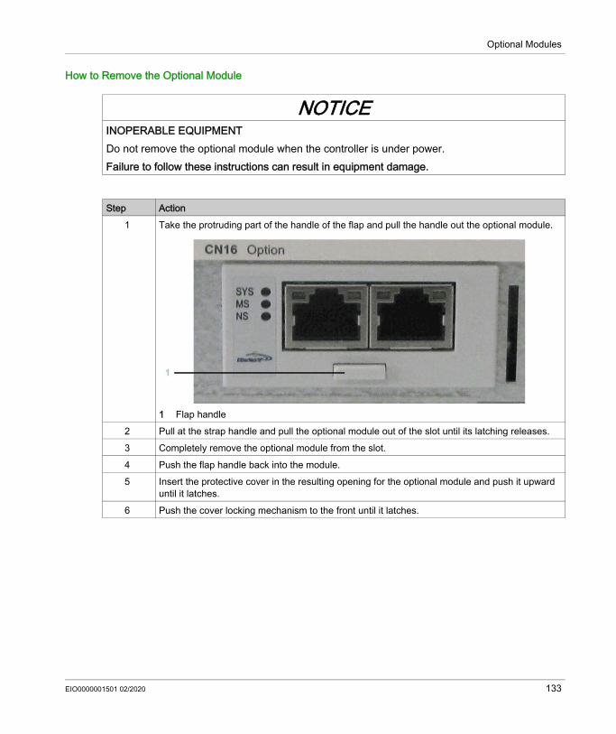
Optional Modules
How to Remove the Optional Module
NOTICEINOPERABLE EQUIPMENTDo not remove the optional module when the controller is under power.Failure to follow these instructions can result in equipment damage.
Step Action1 Take the protruding part of the handle of the flap and pull the handle out the optional module.
1 Flap handle 2 Pull at the strap handle and pull the optional module out of the slot until its latching releases.3 Completely remove the optional module from the slot.4 Push the flap handle back into the module.5 Insert the protective cover in the resulting opening for the optional module and push it upward
until it latches.6 Push the cover locking mechanism to the front until it latches.
EIO0000001501 02/2020 133
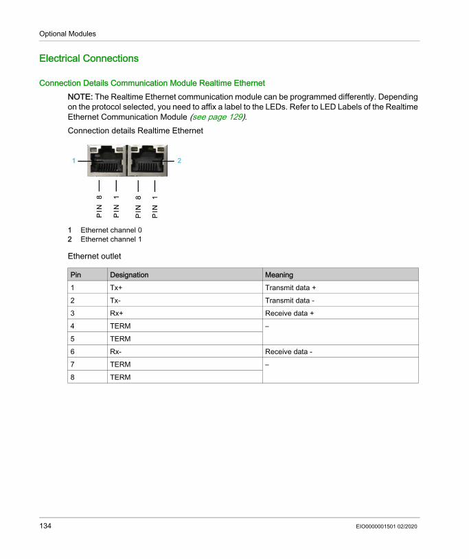
Optional Modules
Electrical Connections
Connection Details Communication Module Realtime EthernetNOTE: The Realtime Ethernet communication module can be programmed differently. Depending on the protocol selected, you need to affix a label to the LEDs. Refer to LED Labels of the Realtime Ethernet Communication Module (see page 129).Connection details Realtime Ethernet
1 Ethernet channel 02 Ethernet channel 1
Ethernet outlet
Pin Designation Meaning1 Tx+ Transmit data +2 Tx- Transmit data -3 Rx+ Receive data +4 TERM –5 TERM6 Rx- Receive data -7 TERM –8 TERM
134 EIO0000001501 02/2020
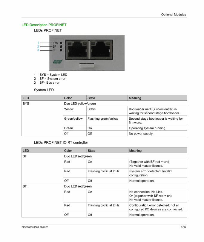
Optional Modules
LED Description PROFINETLEDs PROFINET
1 SYS = System LED 2 SF = System error3 BF= Bus error
System LED
LEDs PROFINET IO RT controller
LED Color State MeaningSYS Duo LED yellow/green
Yellow Static Bootloader netX (= roomloader) is waiting for second stage bootloader.
Green/yellow Flashing green/yellow Second stage bootloader is waiting for firmware.
Green On Operating system running.Off Off No power supply.
LED Color State MeaningSF Duo LED red/green
Red On (Together with BF red = on:)No valid master license.
Red Flashing cyclic at 2 Hz System error detected: Invalid configuration.
Off Off Normal operation.BF Duo LED red/green
Red On No connection: No Link.Or (together with SF red = on)No valid master license.
Red Flashing cyclic at 2 Hz Configuration error detected: not all configured I/O devices are connected.
Off Off Normal operation.
EIO0000001501 02/2020 135
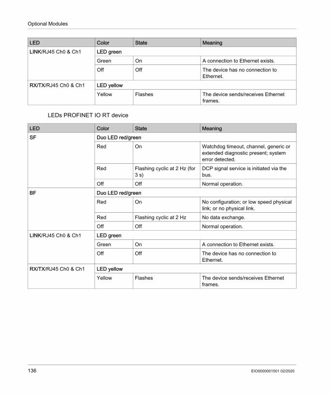
Optional Modules
LEDs PROFINET IO RT device
LINK/RJ45 Ch0 & Ch1 LED greenGreen On A connection to Ethernet exists.Off Off The device has no connection to
Ethernet.RX/TX/RJ45 Ch0 & Ch1 LED yellow
Yellow Flashes The device sends/receives Ethernet frames.
LED Color State Meaning
LED Color State MeaningSF Duo LED red/green
Red On Watchdog timeout, channel, generic or extended diagnostic present; system error detected.
Red Flashing cyclic at 2 Hz (for 3 s)
DCP signal service is initiated via the bus.
Off Off Normal operation.BF Duo LED red/green
Red On No configuration; or low speed physical link; or no physical link.
Red Flashing cyclic at 2 Hz No data exchange.Off Off Normal operation.
LINK/RJ45 Ch0 & Ch1 LED greenGreen On A connection to Ethernet exists.Off Off The device has no connection to
Ethernet.RX/TX/RJ45 Ch0 & Ch1 LED yellow
Yellow Flashes The device sends/receives Ethernet frames.
136 EIO0000001501 02/2020

Optional Modules
LED Description EtherNet/IPLEDs EtherNet/IP
1 SYS= System LED2 MS= Module Status3 NS= Network Status
System LED
LED Color State MeaningSYS Duo LED yellow/green
Yellow Static Bootloader netX (= roomloader) is waiting for second stage bootloader.
Green/yellow Flashing green/yellow Second stage bootloader is waiting for firmware.
Green On Operating system running.Off Off No power supply.
EIO0000001501 02/2020 137
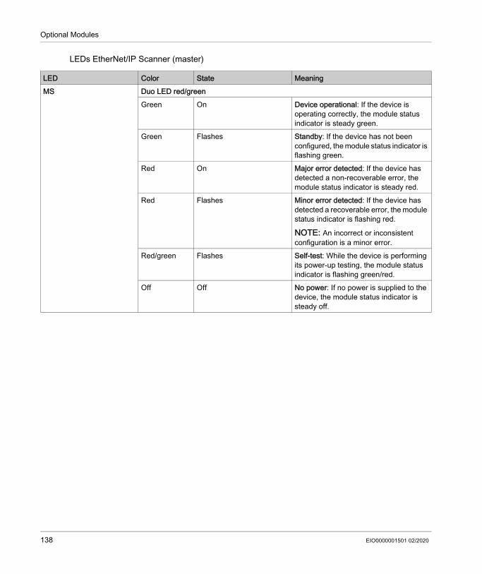
Optional Modules
LEDs EtherNet/IP Scanner (master)
LED Color State MeaningMS Duo LED red/green
Green On Device operational: If the device is operating correctly, the module status indicator is steady green.
Green Flashes Standby: If the device has not been configured, the module status indicator is flashing green.
Red On Major error detected: If the device has detected a non-recoverable error, the module status indicator is steady red.
Red Flashes Minor error detected: If the device has detected a recoverable error, the module status indicator is flashing red.
NOTE: An incorrect or inconsistent configuration is a minor error.
Red/green Flashes Self-test: While the device is performing its power-up testing, the module status indicator is flashing green/red.
Off Off No power: If no power is supplied to the device, the module status indicator is steady off.
138 EIO0000001501 02/2020

Optional Modules
NS Duo LED red/greenGreen On Connected: If the device has at least one
established connection (even to the Message Router), the network status indicator is steady green.
Green Flashes No connections: The device has no established connections, but has obtained an IP address. In this case, the network status indicator flashes green.
Red On Duplicate IP: If the device has detected that its IP address is already in use, the network status indicator is steady red.
Red Flashes Connection timeout: If one or more connections in which this device is the target has timed out, the network status indicator is flashing red. This is left only if all timed out connections are re-established or if the device is reset.
Red/green Flashes Self-test: While the device is performing its power-up testing, the network status indicator is flashing green/red.
Off Off Not powered, no IP address: If the device does not have an IP address (or is powered off), the network status indicator is off.
LINK/RJ45 Ch0 & Ch1 LED greenGreen On A connection to Ethernet exists.Off Off The device has no connection to
Ethernet.ACT/RJ45 Ch0 & Ch1 LED yellow
Yellow Flashes The device sends/receives Ethernet frames.
LED Color State Meaning
EIO0000001501 02/2020 139

Optional Modules
LEDs EtherNet/IP Adapter (slave)
LED Color State MeaningMS Duo LED red/green
Green On Device operational: If the device is operating correctly, the module status indicator is steady green.
Green Flashes Standby: If the device has not been configured, the module status indicator is flashing green.
Red On Major error detected: If the device has detected a non-recoverable error, the module status indicator is steady red.
Red Flashes Minor error detected: If the device has detected a recoverable error, the module status indicator is flashing red.
NOTE: An incorrect or inconsistent configuration is a minor error.
Red/green Flashes Self-test: While the device is performing its power-up testing, the module status indicator is flashing green/red.
Off Off No power: If no power is supplied to the device, the module status indicator is off.
140 EIO0000001501 02/2020

Optional Modules
NS Duo LED red/greenGreen On Connected: If the device has at least one
established connection (even to the Message Router), the network status indicator is steady green.
Green Flashes No connections: If the device has no established connections, but has obtained an IP address, the network status indicator is flashing green.
Red On Duplicate IP: If the device has detected that its IP address is already in use, the network status indicator is steady red.
Red Flashes Connection timeout: If one or more connections in which this device is the target has timed out, the network status indicator is flashing red. This is left only if all timed out connections are re-established or if the device is reset.
Red/green Flashes Self-test: While the device is performing its power-up testing, the network status indicator is flashing green/red.
Off Off Not powered, no IP address: If the device does not have an IP address (or is powered off), the network status indicator is off.
LINK/RJ45 Ch0 & Ch1 LED greenGreen On A connection to Ethernet exists.Off Off The device has no connection to
Ethernet.ACT/RJ45 Ch0 & Ch1 LED yellow
Yellow Flashes The device sends/receives Ethernet frames.
LED Color State Meaning
EIO0000001501 02/2020 141

Optional Modules
LED Description EtherCat-SlaveLEDs EtherCAT-Slave
1 SYS= System LED 2 RUN= Run3 ERR= Error4 Ethernet channel 0 - input port*5 Ethernet channel 0 - output port** Input port and output port are predetermined by firmware and are not configurable.
System LED
LED Color State MeaningSYS Duo LED yellow/green
Yellow Static Bootloader netX (= roomloader) is waiting for second stage bootloader.
Green/yellow Flashing green/yellow Second stage bootloader is waiting for firmware.
Green On Operating system running.Off Off Power supply of the device is missing.
142 EIO0000001501 02/2020
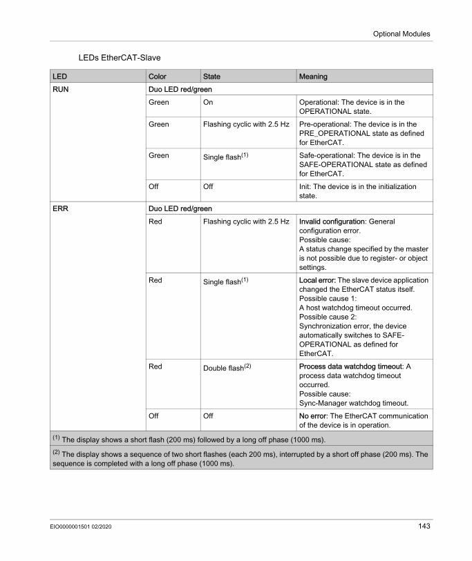
Optional Modules
LEDs EtherCAT-Slave
LED Color State MeaningRUN Duo LED red/green
Green On Operational: The device is in the OPERATIONAL state.
Green Flashing cyclic with 2.5 Hz Pre-operational: The device is in the PRE_OPERATIONAL state as defined for EtherCAT.
Green Single flash(1) Safe-operational: The device is in the SAFE-OPERATIONAL state as defined for EtherCAT.
Off Off Init: The device is in the initialization state.
ERR Duo LED red/greenRed Flashing cyclic with 2.5 Hz Invalid configuration: General
configuration error.Possible cause:A status change specified by the master is not possible due to register- or object settings.
Red Single flash(1) Local error: The slave device application changed the EtherCAT status itself.Possible cause 1:A host watchdog timeout occurred.Possible cause 2:Synchronization error, the device automatically switches to SAFE-OPERATIONAL as defined for EtherCAT.
Red Double flash(2) Process data watchdog timeout: A process data watchdog timeout occurred.Possible cause:Sync-Manager watchdog timeout.
Off Off No error: The EtherCAT communication of the device is in operation.
(1) The display shows a short flash (200 ms) followed by a long off phase (1000 ms).(2) The display shows a sequence of two short flashes (each 200 ms), interrupted by a short off phase (200 ms). The sequence is completed with a long off phase (1000 ms).
EIO0000001501 02/2020 143
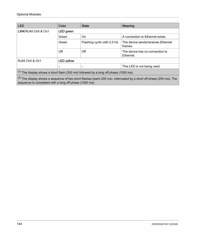
Optional Modules
LINK/RJ45 Ch0 & Ch1 LED greenGreen On A connection to Ethernet exists.Green Flashing cyclic with 2.5 Hz The device sends/receives Ethernet
frames.Off Off The device has no connection to
Ethernet.RJ45 Ch0 & Ch1 LED yellow
– – This LED is not being used.
LED Color State Meaning
(1) The display shows a short flash (200 ms) followed by a long off phase (1000 ms).(2) The display shows a sequence of two short flashes (each 200 ms), interrupted by a short off phase (200 ms). The sequence is completed with a long off phase (1000 ms).
144 EIO0000001501 02/2020

Optional Modules
Communication Module PROFIBUS DP
Section 8.2Communication Module PROFIBUS DP
What Is in This Section?This section contains the following topics:
Topic PageOverview 146Mechanical Installation 147Electrical Connections 150
EIO0000001501 02/2020 145

Optional Modules
Overview
General InformationThe communication module PROFIBUS DP provides a PROFIBUS interface.Communication module PROFIBUS DP - connection
1 PROFIBUS DP connection
After installing the optional module, the controller will automatically detect the module. Then configure it by using the PLC configuration in EcoStruxure Machine Expert Logic Builder.
146 EIO0000001501 02/2020
Optional Modules
Mechanical Installation
Consideration
How to Open the Controller
NOTICEINOPERABLE EQUIPMENTDo not touch the contacts when unpacking or installing the optional module.Failure to follow these instructions can result in equipment damage.
Step Action1 Remove the cover of input CN16 option at the bottom side of the housing. To do this, push the
locking of the cover backward.Result: The cover folds down.
2 Pull the cover to the front and remove it.
EIO0000001501 02/2020 147

Optional Modules
How to Install the Optional Module
NOTE: Ensure that the module is flush at the edge.
NOTICEINCORRECT INSERTION OF OPTIONAL MODULE Do not insert the optional module when the controller is under power. Verify that the springs at the bottom side of the module are located at the printed circuit board
side when you insert the module into the slot.Failure to follow these instructions can result in equipment damage.
Step Action1 Ensure that the controller is switched off.2 Insert the module into the slot and push against the printed circuit board until both front springs
at the bottom side lower into the openings on the printed circuit board.
Result: The module rests on the lower edge of the slot.3 Slightly apply pressure and push the module further inside until it is flush at the edge.
Result: The springs at the bottom side reach into the openings of the printed circuit board.
148 EIO0000001501 02/2020
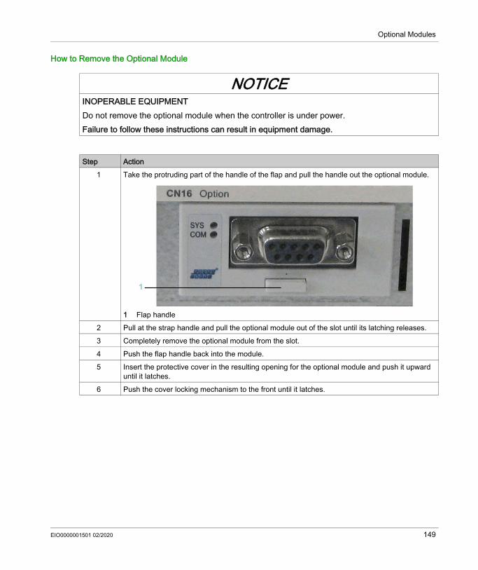
Optional Modules
How to Remove the Optional Module
NOTICEINOPERABLE EQUIPMENTDo not remove the optional module when the controller is under power.Failure to follow these instructions can result in equipment damage.
Step Action1 Take the protruding part of the handle of the flap and pull the handle out the optional module.
1 Flap handle 2 Pull at the strap handle and pull the optional module out of the slot until its latching releases.3 Completely remove the optional module from the slot.4 Push the flap handle back into the module.5 Insert the protective cover in the resulting opening for the optional module and push it upward
until it latches.6 Push the cover locking mechanism to the front until it latches.
EIO0000001501 02/2020 149
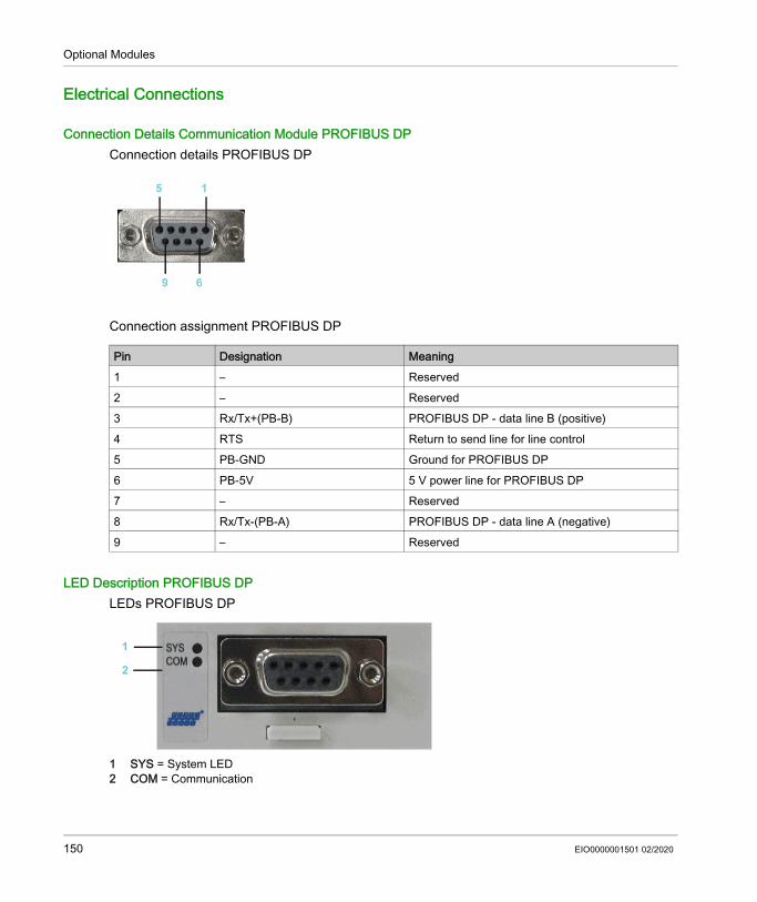
Optional Modules
Electrical Connections
Connection Details Communication Module PROFIBUS DPConnection details PROFIBUS DP
Connection assignment PROFIBUS DP
LED Description PROFIBUS DPLEDs PROFIBUS DP
1 SYS = System LED 2 COM = Communication
Pin Designation Meaning1 – Reserved2 – Reserved3 Rx/Tx+(PB-B) PROFIBUS DP - data line B (positive)4 RTS Return to send line for line control5 PB-GND Ground for PROFIBUS DP6 PB-5V 5 V power line for PROFIBUS DP7 – Reserved8 Rx/Tx-(PB-A) PROFIBUS DP - data line A (negative)9 – Reserved
150 EIO0000001501 02/2020

Optional Modules
System LED
LEDs PROFIBUS DP master - 1 communication LED (current hardware revision)
LEDs PROFIBUS DP slave - 1 communication LED (current hardware revision)
LED Color State MeaningSYS Duo LED yellow/green
Yellow Static Bootloader netX (= roomloader) is waiting for second stage bootloader.
Green/yellow Flashing green/yellow Second stage bootloader is waiting for firmware.
Green On Operating system running.Off Off No power supply.
LED Color State MeaningCOM Duo LED red/green
Green Flashing acyclic No configuration or stack error detected.
Green Flashing cyclic PROFIBUS is configured, but bus communication is not yet released from the application.
Green On Communication to all slaves is established.
Red Flashing cyclic Communication to at least one slave is disconnected.
Red On Communication to one/all slaves is disconnected.
LED Color State MeaningCOM Duo LED red/green
Green On RUN, cyclic communication.Red Flashing cyclic STOP, no communication,
connection error detected.Red Flashing acyclic Not configured.
EIO0000001501 02/2020 151

Optional Modules
152 EIO0000001501 02/2020
PacDrive Logic Motion Controller
EIO0000001501 02/2020
Appendices
What Is in This Appendix?The appendix contains the following chapters:
Chapter Chapter Name PageA Further Information on the Manufacturer 155B Disposal 159C Units and Conversion Tables 161
EIO0000001501 02/2020 153

154 EIO0000001501 02/2020

PacDrive Logic Motion ControllerFurther Information on the ManufacturerEIO0000001501 02/2020
Further Information on the Manufacturer
Appendix AFurther Information on the Manufacturer
What Is in This Chapter?This chapter contains the following topics:
Topic PageContact Addresses 156Product Training Courses 157
EIO0000001501 02/2020 155

Further Information on the Manufacturer
Contact Addresses
Schneider Electric Automation GmbHSchneiderplatz 197828 Marktheidenfeld, GermanyPhone: +49 (0) 9391 / 606 - 0Fax: +49 (0) 9391 / 606 - 4000Email: [email protected]: www.schneider-electric.com
Machine Solution ServiceSchneiderplatz 197828 Marktheidenfeld, GermanyPhone: +49 (0) 9391 / 606 - 3265Fax: +49 (0) 9391 / 606 - 3340Email: [email protected]: www.schneider-electric.com
Additional Contact AddressesSee the homepage for additional contact addresses:www.schneider-electric.com
156 EIO0000001501 02/2020

Further Information on the Manufacturer
Product Training Courses
Product Training CoursesSchneider Electric offers a number of product training courses.The Schneider Electric training instructors will help you take advantage of the extensive possibilities offered by the system.See the website (www.schneider-electric.com) for further information and the seminar schedule.
EIO0000001501 02/2020 157

Further Information on the Manufacturer
158 EIO0000001501 02/2020

PacDrive Logic Motion ControllerDisposalEIO0000001501 02/2020
Disposal
Appendix BDisposal
Disposal
Information on the Disposal of Schneider Electric ProductsNOTE: The components consist of different materials which can be recycled and must be disposed of separately.
Step Action1 Dispose of the packaging in accordance with the relevant national regulations.2 Dispose of the packaging at the disposal sites provided for this purpose.3 Dispose of controller in accordance with the applicable national regulations.
EIO0000001501 02/2020 159

Disposal
160 EIO0000001501 02/2020

PacDrive Logic Motion ControllerUnits and Conversion TablesEIO0000001501 02/2020
Units and Conversion Tables
Appendix CUnits and Conversion Tables
Units and Conversion Tables
Length
Mass
Force
– in ft yd m cm mmin – / 12 / 36 * 0.0254 * 2.54 * 25.4ft * 12 – / 3 * 0.30479 * 30.479 * 304.79yd * 36 * 3 – * 0.9144 * 91.44 * 914.4m / 0.0254 / 0.30479 / 0.9144 – *100 *1000cm / 2.54 / 30.479 / 91.44 / 100 – * 10mm / 25.4 / 304.79 / 914.4 / 1000 / 10 –
– lb oz slug 0.22 kg glb – * 16 * 0.03108095 * 0.4535924 * 453.5924oz / 16 – * 1.942559*10-3 * 0.02834952 * 28.34952
slug / 0.03108095 / 1.942559*10-3 – * 14.5939 * 14593.9
0.22 kg / 0.45359237 / 0.02834952 / 14.5939 – *1000g / 453.59237 / 28.34952 / 14593.9 / 1000 –
– lb oz p dyne Nlb – * 16 * 453.55358 * 444822.2 * 4.448222oz / 16 – * 28.349524 * 27801 * 0.27801p / 453.55358 / 28.349524 – * 980.7 * 9.807*10-3
dyne / 444822.2 / 27801 / 980.7 – / 100*103
N / 4.448222 / 0.27801 / 9.807*10-3 * 100*103 –
EIO0000001501 02/2020 161

Units and Conversion Tables
Power
Rotation
Torque
Moment of Inertia
– HP WHP – * 746W / 746 –
– min-1(rpm) rad/s deg./s
min-1(rpm) – * π / 30 * 6
rad/s * 30 / π – * 57.295deg./s / 6 / 57.295 –
– lb•in lb•ft oz•in Nm kp•m kp•cm dyne•cmlb•in – / 12 * 16 * 0.112985 * 0.011521 * 1.1521 * 1.129*106
lb•ft * 12 – * 192 * 1.355822 * 0.138255 * 13.8255 * 13.558*106
oz•in / 16 / 192 – * 7.0616*10-3 * 720.07*10-6 * 72.007*10-3 * 70615.5
Nm / 0.112985 / 1.355822 / 7.0616*10-3 – * 0.101972 * 10.1972 * 10*106
kp•m / 0.011521 / 0.138255 / 720.07*10-6 / 0.101972 – * 100 * 98.066*106
kp•cm / 1.1521 / 13.8255 / 72.007*10-3 / 10.1972 / 100 – * 0.9806*106
dyne•cm / 1.129*106 / 13.558*106 / 70615.5 / 10*106 / 98.066*106 / 0.9806*106 –
– lb•in2 lb•ft2 kg•m2 kg•cm2 kg•cm2•s2 oz•in2
lb•in2 – / 144 / 3417.16 / 0.341716 / 335.109 * 16
lb•ft2 * 144 – / 3 * 0.30479 * 30.479 * 304.79
kg•m2 * 3417.16 / 0.04214 – * 0.9144 * 91.44 * 914.4
kg•cm2 * 0.341716 / 421.4 / 0.9144 – * 100 * 1000
kg•cm2•s2 * 335.109 / 0.429711 / 91.44 / 100 – * 10
oz•in2 / 16 / 2304 / 54674 / 5.46 / 5361.74 –
162 EIO0000001501 02/2020

Units and Conversion Tables
Temperature
Conductor Cross-section
– °F max K°F – (°F - 32) * 5/9 (°F - 32) * 5/9 + 273.15max °C * 9/5 + 32 – °C + 273.15K (K - 273.15) * 9/5 + 32 K - 273.15 –
AWG 1 2 3 4 5 6 7 8 9 10 11 12 13
mm2 42.4 33.6 26.7 21.2 16.8 13.3 10.5 8.4 6.6 5.3 4.2 3.3 2.6
AWG 14 15 16 17 18 19 20 21 22 23 24 25 26
mm2 2.1 1.7 1.3 1.0 0.82 0.65 0.52 0.41 0.33 0.26 0.20 0.16 0.13
EIO0000001501 02/2020 163

Units and Conversion Tables
164 EIO0000001501 02/2020

PacDrive Logic Motion ControllerIndexEIO0000001501 02/2020
Index
Bbending cycles, 47
Ccertifications, 121climatic, 42condensate, 43contact addresses, 156cooling units, 43
Ddaisy chain connector box, 26daisy chain wiring, 26degree of protection, 41domestic appliances, 18
Ffloating systems, 18
Hhazardous, explosive atmospheres, 18homepage, 156
Iintended use, 8IP, 41
Llife support system, 18
Mmachine grounding, 46mechanical, 42
EIO0000001501 02/2020
minimum bending radius, 47minimum cross sections, 46mobile systems, 19
Pportable systems, 19product related information, 14
Qqualification of personnel, 8
Sseminars, 156service addresses, 156
Ttemperature limit, 43training courses, 156
Uunderground, 18
Wwiring, 46
165