Pabx Panasonic Kx-tde100
96
HIMARK, CHINA PABX Panasonic KX- TDE100
Transcript of Pabx Panasonic Kx-tde100

HIMARK, CHINA
PABX Panasonic KX-TDE100

CONTENTS
1. General Introduction 2. Hardware Structure 3. Installation 4. PABX Configuration 5. DT333 Introduction 6. Operation

1. General Introduction The KX-TDE100 converged architecture is extremely versatile,
providing multiple options to meet the expansion needs of growing business. To increase the system capacity, the free slot design allows to add cards to accommodate additional extensions, Cos, or features, or can also expand the system by adding licenses to activate the system’s built-in virtual IP ports. The converged architecture provides easy, cost-effective solutions to meet expansion needs, so the client can grow communications network without having to purchase a new system


Feature list 1

Feature list 2


2. Hardware Structure

A: RUN indicatorB: ALARM indicatorC: MNT portD: CTI portE: PSU slotF: Zero slot (without any card)G: Free slots (left1~6)H: TDEMPR slotI: RS2232 port

KX-TDE100 configuration for MOA Project
1 8-channel analog trunk board KX-TDA0180 pcs 1
2 8-channel outside caller ID board KX-TDA0193 pcs 1
3 30-channel PRI digital trunk board KX-TDA0290 pcs 1
416-channel caller ID extension
boardKX-TDA0177 pcs 1
5 8-channel digital extension board KX-TDA0171 pcs 1
6 2-channel voice message card KX-TVM50 pcs 1
7 64-channel digital signal processor KX-TDE0111 pcs 1
8 Basic board KX-TDA0190 pcs 1
9 4-port doorphone board KX-TDA0161 pcs 1

2.1 TDEMPR card
MNT/CTI PORT PIN

LED indicatorIndicator Color Description
BATT ALARM Red Battery alarm
Off: normal
On: alarm
SD ACCESS Green SD statue
On: Is accessing
10BASE-T/100BASE-TX
MNT 2 LINK Green Connection status
Off: off line
On: connection normal
Flash: communication
100 Yellow Data speed indicator
Off:10 Mbps
On: 100Mbps
CTI 1 LINK Green Connection status
Off: off line
On: connection normal
Flash: communication
100 Yellow Data speed indicator
Off:10 Mbps
On: 100Mbps

2.2 LOCT 8 card----KX-TDA0180
LED Indicator
Indicator Color Description
CARD STATUS Green / Red
Off: power off
Green on: normal
Green flash :normal (one port is using)
Red on: faulty (including reset)
Red flash: stop

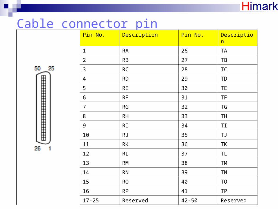
Cable connector pinPin No. Description Pin No. Description
1 RA 26 TA
2 RB 27 TB
3 RC 28 TC
4 RD 29 TD
5 RE 30 TE
6 RF 31 TF
7 RG 32 TG
8 RH 33 TH
9 RI 34 TI
10 RJ 35 TJ
11 RK 36 TK
12 RL 37 TL
13 RM 38 TM
14 RN 39 TN
15 RO 40 TO
16 RP 41 TP
17-25 Reserved 42-50 Reserved

2.3 PRI 30 CARD----KX-TDA0290
Switch setting
switch Description120/75 75Ω for BNC, 120 Ω for RJ45
A/B Using RJ45, A for CO, B for ext.
Using BNC, just A

Port description
RJ45 for Co. RJ45 for EXT. RJ45 for Co.
BNC TX BNC RX

LED IndicatorIndicator Color Description
CARD STATUS Green/Red Off: power off
Green on: normal
Green flash :normal (one port is using)
Red on: faulty (including reset)
Red flash: stop
SYNC-ERR Red Off: normal
On: out-sync
RAI Red Off: normal
On: alarm (slave clock)
Flash: alarm (master clock)
AIS Red Off: normal
On: alarm
SYNC GREEN Off: out-sync
On: sync
Flash: sync (master clock)
D-LINK Green Off: non-link
On: link

2.4 DLC8 CARD----KX-TDA0171
LED Indicator
Indicator Color Description
CARD STATUS
Green /Orange/ Red
Off: power off
Green on: normal
Green flash :normal (one port is using)
Orange flash: inspect the PT port with CS
Red on: faulty (including reset)
Red flash: stop

Cable connector pinPin No. Description Pin No. Description
1 Reserved 26 Reserved
2 D2A 27 D1A
3-4 Reserved 28-29 Reserved
5 D2B 30 D1B
6-7 Reserved 31-32 Reserved
8 D2C 33 D1C
9-10 Reserved 34-35 Reserved
11 D2D 36 D1D
12=13 Reserved 37-38 Reserved
14 D2E 39 D1E
15-16 Reserved 40-41 Reserved
17 D2F 42 D1F
18-19 Reserved 43-44 Reserved
20 D2G 45 D1G
21-22 Reserved 46-47 Reserved
23 D2H 48 D1H
24-25 Reserved 49-50 Reserved

2.5 CLSLC16 CARD------KX-TDA0177
LED Indicator
Indicator Color Description
CARD STATUS
Green /Red Off: power off
Green on: normal
Green flash :normal (one port is using)
Red on: faulty (including reset)
Red flash: stop
Cable connector pinPin No. Description Pin No. Description
1 RA 26 TA
2 RB 27 TB
3 RC 28 TC
4 RD 29 TD
5 RE 30 TE
6 RF 31 TF
7 RG 32 TG
8 RH 33 TH
9 RI 34 TI
10 RJ 35 TJ
11 RK 36 TK
12 RL 37 TL
13 RM 38 TM
14 RN 39 TN
15 RO 40 TO
16 RP 41 TP
17-25 Reserved 42-50 Reserved
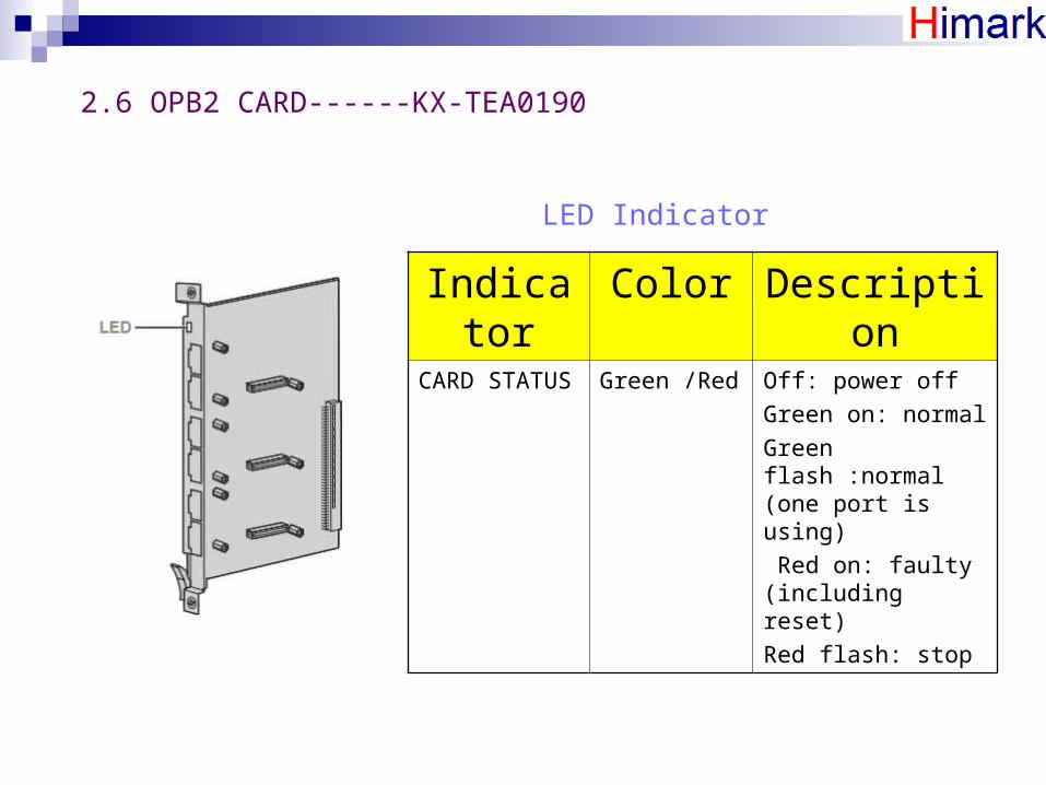
2.6 OPB2 CARD------KX-TEA0190
LED Indicator
Indicator Color Description
CARD STATUS
Green /Red Off: power off
Green on: normal
Green flash :normal (one port is using)
Red on: faulty (including reset)
Red flash: stop

3. Installation3.1 Open/close the front cover
Open the front cover
Step 1

Step 2
Step 3

Close the front cover
Step 1
Step 2Step 3

3.2 Grounding
PSU CARD

3.3 Insert/remove the cards
Insert the cards
Step 1
Step 2
Step 3

Cover empty slot

Cable management

Remove the card
Step 2
Step 1

3.4 connectors and pin No.
cable
terminal
Small plug

3.5 SD CARD installation

4. PABX Configuration
4.1 PC Connect with PABX
Via MNT port in TEEMPR card, Max. distance is 5m
Note: PC need config. IP address

Via RS232 port in TEEMPR card. Max. distance is 2m
Note: PC and PABX should be in same voltage level.

4.2 Initialize PABX ---KX-TDE100
Step 1 insert SD
Step2 Switch on system initialize
Step3 Power On

Step 4 press resetStep 5 switch on Normal
Indicator Color Description
RUN Green Off: power off
On: power on and run (link)
Flash (slow): start-up
Flash (fast): start-up or reset for without SD or switch on initialize
ALARM Red Off: normal
On: alarm (CPU stop)
Flash: alarm (TDEMPR file error)
Note: after this operation, all the cards data are lost.

4.3 Run Maintenance console


4.4 configuration slots


After configure all the big cards, we still configure the daughter cards.

If PC connect with PABX, then all the data will automatically load to PC from the equipment.

4.5 configure cards
a. TDEMPR card


b. LCOT8 card
Only need set if CO connect then this as “INS”, if not this as “OUS”

c. CSLC16 card

d. DLC8 card
This setting for voice processing unit.
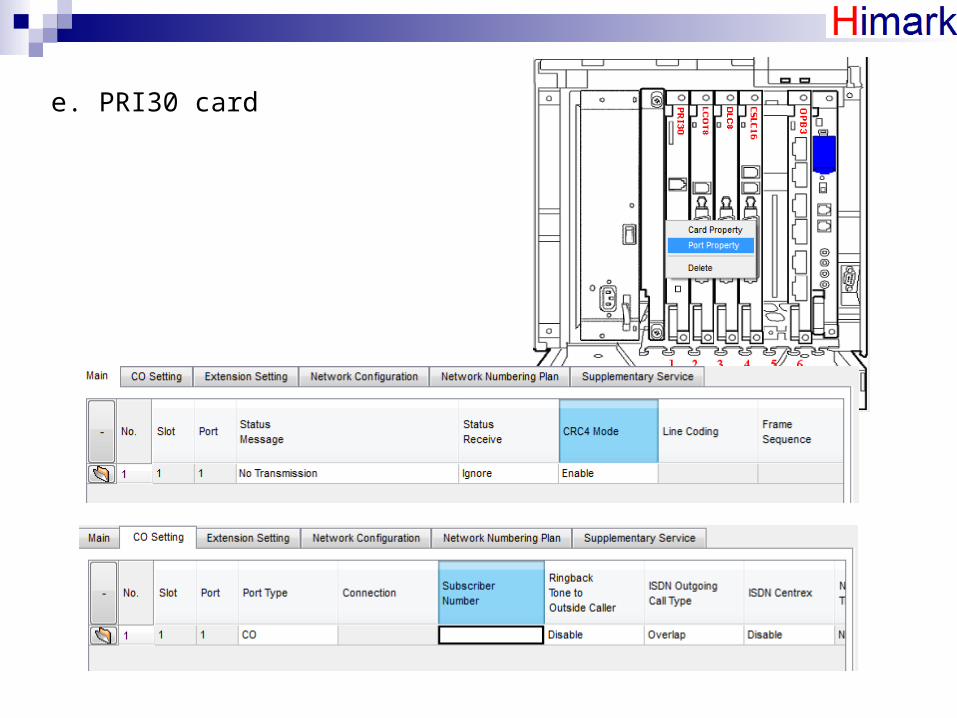
e. PRI30 card

4.6 System configuration
Set operator and holding music

Set week table

Set number plan


Set class of service
Step 1: set level ruler

Step 2: set level content

4.7 Group configuration
Ring: all the phone in one group are ringing at same time. UCD: all the phone in one group is ringing one by one. Priority Hunting: all the phone in one group is ringing according
to the Priority.

Add the group member

4.8 Extension number configuration


Call out

Set DT333 Speed dial

EXAMPLE

4.9 Door phone configuration

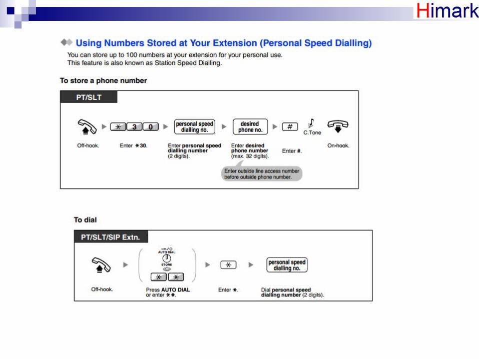
4.10 System speed dialing configuration

5. DT333 Introduction


setting

6. Operation
6.1 Making calls
Basic calling


Easy dialing


When the dialed line is busy or there is no answer


6.2 Receiving calls

Using answer/release button


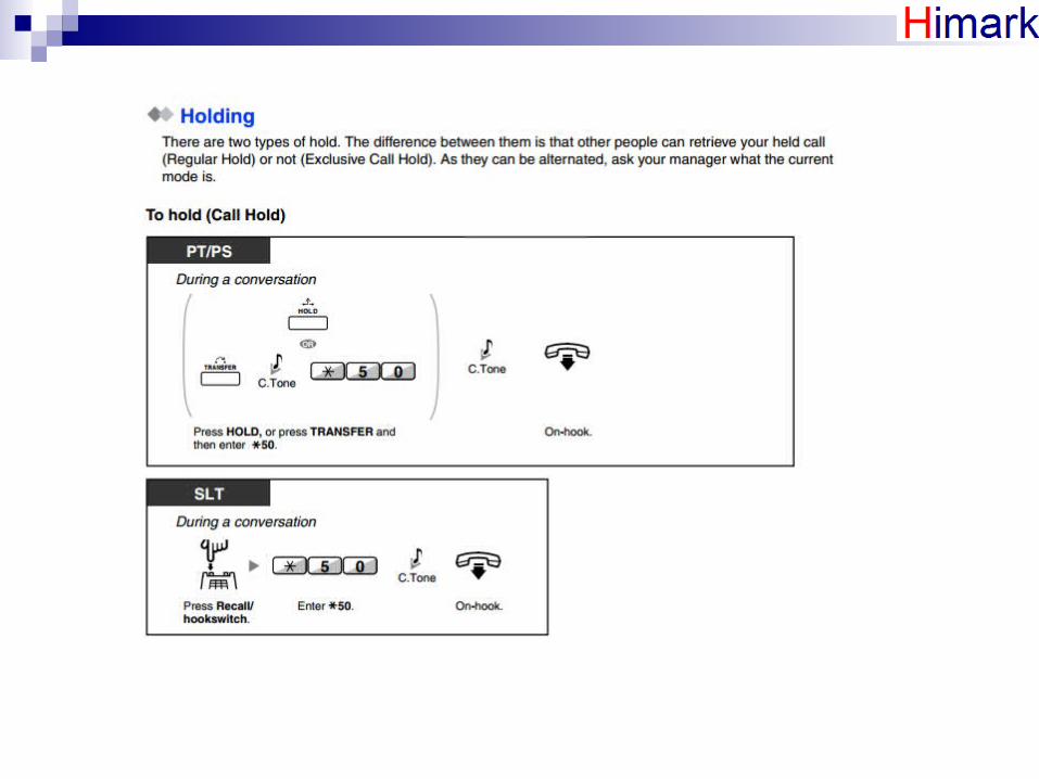
6.3 During a conversation


6.4 Voice mail service