PA-44-180 Seminole Multi-Engine Study Guide
28
PA-44-180 Seminole Multi-Engine Study Guide 4700 Airport Parkway, Addison, Texas 75001 Tel: (972) 735-9099 Email: [email protected] www.thrustflight.com
Transcript of PA-44-180 Seminole Multi-Engine Study Guide

PA-44-180 Seminole
Multi-Engine Study Guide
4700 Airport Parkway, Addison, Texas 75001 Tel: (972) 735-9099
Email: [email protected] www.thrustflight.com

Thrust Flight - Seminole Multi Engine Study Guide
The Thrust Flight Study Guide is for reference only and is intended only to supplement, not replace, manufacturer and FAA publications such as the pilots operating handbook. All pilots must operate the aircraft in accordance with the Pilot’s Operating Handbook and abide by Federal Aviation Regulations.
Section 1: 3
Engine-out Aerodynamics 3 TURNING TENDENCIES 3 CRITICAL ENGINE 3 WHAT HAPPENS WHEN AN ENGINE FAILS? 3 ZERO SIDESLIP CONDITION 4 CLIMB PERFORMANCE AND SERVICE CEILING 4 Vmc- MINIMUM CONTROL SPEED 5 §23.149 Minimum Control Speed 5 RECOGNIZING AND RECOVERING FROM Vmc 6 DENSITY ALTITUDE AND ITS RELATIONSHIP TO STALL SPEED 6 FACTORS AFFECTING Vmc AND SINGLE ENGINE PERFORMANCE 6
Section 2: 8
Aircraft Systems and Limitations 8 SPEEDS (KIAS) 9 MANEUVERS 9 KINDS OF OPERATION 10 ENGINES 10 Propellers 10 Fuel 12 FLIGHT CONTROLS 13 TRIM CONTROL 13 FLAPS 13 ELECTRICAL SYSTEM 13 LANDING GEAR 15 ENVIRONMENTAL 17 BRAKES 18 PITOT-STATIC 18 VACUUM SYSTEM 19
Section 3: Normal Flight Procedures 20 PASSENGER BRIEFING 20 PRE-START 20 TAXI 20 PRE-TAKEOFF BRIEFING 20

Thrust Flight - Seminole Multi Engine Study Guide
TAKE-OFF 21 CLIMB 21 CRUISE 21 DESCENT 21 TRAFFIC PATTERN ENTRY AND NORMAL LANDINGS 21 AFTER LANDING 22 SHORT FIELD VISUAL APPROACH AND LANDING 22 SHORT FIELD TAKEOFF 23 GO-AROUND/ MISSED APPROACH 23 PRECISION APPROACH 24 NON-PRECISION APPROACH 24 CIRCLING APPROACH 25 HOLDING 25
Section 4: Emergency Procedures 26 MEMORIZE! 26 IN-FLIGHT ENGINE FAILURE 26 MEMORIZE! 26 ENGINE FAILURE DURING GROUND ROLL 26 REVIEW 27 ENGINE FAILURE-- SECURE INOP ENGINE “FEATHER” 27

Thrust Flight - Seminole Multi Engine Study Guide
Section 1: Engine-out Aerodynamics
TURNING TENDENCIES The turning tendencies that affect a single engine aircraft (p-factor, torque, spiraling slipstream, gyroscopic precession) will also affect a multi-engine aircraft. Because a multi-engine aircraft has two engines many of these turning tendencies increase.
A twin engine aircraft where both engines are rotating the same direction is called a conventional twin . To combat p-factor and torque, aircraft with counter-rotating propellers have been developed (the PA44 Seminole has counter-rotating propellers). The p-factor and torque from counter-rotating propellers cancel each other out which results in less rudder needed to oppose their turning tendencies.
CRITICAL ENGINE A critical engine is the engine which, if lost, will most adversely affect the performance and handling characteristics of the aircraft. The effect of the critical engine is most significant when the aircraft is operating at low airspeed with a high power setting (thus more p-factor and torque).
On a conventional twin with propellers rotating clockwise, the critical engine is the left engine. On an aircraft such as the Seminole with counter-rotating propellers there is not a critical engine because the yawing and rolling caused from losing either engine is identical. There are four factors which determine if an engine is critical:
1. P -Factor 2. A ccelerated Slipstream 3. S piraling Slipstream 4. T orque
WHAT HAPPENS WHEN AN ENGINE FAILS? Two things happen when an engine fails: The aircraft will Yaw and Roll towards the dead engine because now lift, thrust, and drag act on your aircraft asymmetrically.
1. Yaw - Asymmetrical thrust will cause a yawing motion around the C.G. toward the inoperative engine.
2. Roll - Induced flow ( Accelerated Slipstream - extra lift created by accelerated air over the wing) from the operating engine and lack of induced flow from the inoperative engine causes asymmetric lift on wings. This results in a rolling moment around the C.G. towards the inoperative engine.
3. Roll - Yawing moment from the asymmetric thrust will cause the operating engine to move faster through the air as the aircraft yaws. This causes faster velocity air to flow

Thrust Flight - Seminole Multi Engine Study Guide
over the operating engine’s wing causing more lift on that wing, thus rolling towards the inoperative engine.
To counteract this roll and yaw, rudder pressure must be applied to the side of the operational engine to oppose these forces. Hence, “ Dead foot- Dead engine” .
ZERO SIDESLIP CONDITION The solution to maintaining aircraft heading and reducing drag is to improve performance using the Zero Sideslip Condition. When the aircraft is banked into the operating engine (2-5 degrees of bank), the dihedral of the wing will create a horizontal component of lift. The horizontal component of lift minimizes rudder deflection required to align the longitudinal axis of the aircraft to the relative wind. In addition to banking into the operating engine, the appropriate amount of rudder required is indicated by the inclinometer ball being “split” towards the operating engine’s side. The zero sideslip condition must be flown for optimum aircraft performance.
CLIMB PERFORMANCE AND SERVICE CEILING Climb performance is dependent on the excess power needed to overcome drag. When a twin-engine airplane loses an engine, the airplane loses 50% of its available power. This power loss results in a loss of approximately 80% of the aircraft’s excess power and climb performance. Drag is a major factor relative to the amount of excess power available. An increase in drag (such as the loss of one engine) must be offset by additional power. This additional power is now taken from the excess power, making it unavailable to aid the aircraft in the climb. When an engine is lost, maximize thrust (full power) and minimize drag (flaps and gear up, feather prop, etc) in order to achieve optimum single engine climb performance. Drag Factors:
1. Full Flaps- ~400 fpm approx. 2. Windmilling Prop- ~400 fpm approx. 3. Gear Extended- ~150 fpm approx.
Single-engine service ceiling- the highest altitude at which the airplane can maintain a steady rate of climb of 50 fpm with one engine operating at full power and one engine’s propeller feathered

Thrust Flight - Seminole Multi Engine Study Guide
Single-engine absolute ceiling- the altitude where climb is no longer possible with one engine operating at full power and one engine’s propeller is feathered
Vmc- MINIMUM CONTROL SPEED Rudder is applied to counteract yaw and roll from an inoperative engine in a multi-engine aircraft. As airspeed decreases the rudder becomes less effective, eventually an airspeed will be reached where full rudder deflection is required to maintain directional control. At this point, any further airspeed reduction will result in a loss of directional control. This airspeed is Vmc, the airspeed at which it is still possible to maintain directional control with an engine inoperative. This is the point where the force created by the operating engine combined with the drag from the failed engine is more than the force created by the deflected rudder, resulting in a loss of directional control.
§23.149 Minimum Control Speed Vmc is the calibrated airspeed, at which, when the critical engine is suddenly made inoperative it is possible to:
1. Maintain control of the airplane with the engine still inoperative 2. Maintain straight flight at the same speed with an angle of bank not more than 5
degrees.
The method used to simulate a critical engine failure must represent the most critical aircraft configuration and situation with respect to controllability.Vmc must not exceed 1.2 Vs1 at maximum takeoff weight.
Vmc must be determined with: 1. Most unfavorable weight (not necessarily gross weight) 2. Most unfavorable center of gravity position 3. The airplane airborne and the ground effect negligible 4. Maximum available takeoff power on Operative Engine 5. The airplane trimmed for takeoff 6. Flaps in the takeoff position 7. Landing gear retracted 8. All propeller controls in the recommended takeoff position 9. Critical Engine Inoperative and Windmilling
When recovering from Vmc: 1. The rudder pedal force required to maintain control must not exceed 150 pounds 2. It must not be necessary to reduce power of the operative engine(s) 3. The airplane must not assume any dangerous attitude 4. It must be possible to prevent a heading change of more than 20 degrees

Thrust Flight - Seminole Multi Engine Study Guide
RECOGNIZING AND RECOVERING FROM Vmc There are four warning signs that Vmc is occurring or about to occur:
1. Loss of directional control - the rudder pedal is depressed to its fullest travel and the airplane is still turning towards the inoperative engine Stall warning horn- a single engine stall may be just as dangerous as running out of rudder authority and could even result in a spin
2. Buffeting before the stall- same reason as the stall warning horn 3. A rapid decay of control effectiveness- any loss of control effectiveness could result in
a loss of control of the aircraft
To recover from Vmc, these two actions must occur simultaneously : 1. Reduce power on the operating engine- this will reduce the asymmetrical thrust
causing the Vmc in the first place (remember, reducing power all the way to idle may help stop the Vmc, but the loss of airspeed and power can lead to a stall)
2. Pitch down- lowering the nose of the airplane will increase the forward airspeed making the rudder more effective in regaining and maintaining directional control
DENSITY ALTITUDE AND ITS RELATIONSHIP TO STALL SPEED
As density altitude increases, V mc speed will decrease because as density altitude increases engine power will decrease (less engine power at higher density altitude🡪 less asymmetric thrust🡪 less yaw towards dead engine= lower ). Stall speed is an indicated airspeed which will remain constant as altitude increases or decreases.
FACTORS AFFECTING Vmc AND SINGLE ENGINE PERFORMANCE Vmc is defined using a very specific set of conditions, thus published Vmc and actual Vmc can be two very different numbers. Remember, Vmc only addresses directional control and is not related to aircraft performance. While controllability is important, the degradation of performance in a single engine situation also has serious consequences. A variety of factors affect both controllability and performance with one engine inoperative, such as aircraft configuration, flight conditions, and pilot action. In some cases, an element which provides an increase in controllability (translating into a decrease in Vmc) may actually hinder performance. Refer to the chart on the next page to review how certain factors affect both Vmc and performance

Thrust Flight - Seminole Multi Engine Study Guide
EFFECT ON PERFORMANCE Vmc Power Increase Up- more power Up- more yaw
Temp Increase Down- less dense, less power Down- less dense, less power, less yaw
Pressure Decrease Down- less dense, less power Down- less dense, less power, less yaw
Density Altitude Increase Down- less dense, less power Down- less dense, less power, less yaw
Bank Angle- 0 bank- no turn
Down- more drag- slipping Up- sideslip plane- less AOA on rudder because of sideslip airflow- less rudder
effectiveness- more rudder needed
Zero Sideslip- 2-3 bank- no turn
Up- less drag- zero slip Middle- Use horizontal lift to stop turn- not slipping- more rudder effectiveness
Bank Angle- 5 bank Up- less drag- fuselage aligned with wind Down- plane turning toward good engine + rudder used to stop turn = slip toward good
engine- high AOA on rudder
Windmilling Propeller Down- more drag Up- more drag, more yaw
Feathered Propeller Up- less drag Down- less drag, less yaw
Aft CG Up- less tail down force required less induced drag; Down- smaller arm on controls, less control effectiveness
Up- less distance between rudder and CG- less rudder effectiveness
Heavier Weight Down- more weight, more power required Down- more lift needed in level flight- more horizontal lift available during turn- helps
prevent turn
Flaps Down Down- more airflow over flap causes greater drag, increased yaw, increased
roll, requiring more aileron to stop, creating more adverse yaw= more induced
drag
Down- more induced drag from good engine side prevents yaw towards dead engine
Gear Down Down- more parasitic drag Depends on location of CG to gear and direction of travel (Vmc down, keel effect)
Critical Engine Fails Down- larger control inputs Up- P-factor, Accelerated Slipstream, Torque makes yaw worst
In Ground Effect Up- less drag Down- less drag Improved Controllability

Thrust Flight - Seminole Multi Engine Study Guide
Section 2:
Aircraft Systems and Limitations
This study guide is only to supplement the aircraft POH, not to replace it. Refer to aircraft POH for official operating limitations and systems information. It is the pilot’s responsibility to be
familiar with all information in the Pilot's Operating Handbook.

Thrust Flight - Seminole Multi Engine Study Guide
V- SPEEDS (KIAS)
V R V X V XSE V Y V YSE V SSE V SO V S1 V MC V A V A V NO V NE V LR V LE /V LO V FE X-Wind
Rotation Speed Best Angle of Climb Best Angle 1 Engine Best Rate of Climb Best Rate 1 Engine Single Engine Intentional Safe Speed Stall Speed Landing Configuration Stall Speed Clean Configuration Minimum Control Speed Maneuvering Speed (Max Gross) Maneuvering Speed (2700lbs) Max Structural Cruising Speed Never Exceed Speed Max Gear Retraction Speed Max Gear Extending and Extended Speed Flap Extension Speed Max Demonstrated Crosswind
75 82 82 88 88 82 55 57 56 135 112 169 202 109 140 111 17
MAXIMUM CERTIFICATED AND STANDARD AIRCRAFT WEIGHTS
Maximum Ramp Weight 3816lbs
Maximum Take-off Weight 3800lbs
Maximum Landing Weight 3800lbs
Maximum Weight in Baggage Compartment 200lbs
CENTER OF GRAVITY Forward Limits: 84 in aft of datum at 2800 lbs, then straight line variation to 89 in aft of datum at a weight of 3800 lbs. Aft Limit: 93 in aft of datum at all weights.
MANEUVERS This is a normal category airplane. Aerobatic maneuvers, including spins, are prohibited.
LOAD FACTORS (3800 lbs) Positive maneuvering load factors: Flaps Up 3.8G Flaps Down (DN) 2.0G

Thrust Flight - Seminole Multi Engine Study Guide
KINDS OF OPERATION Minimum Flight Crew 1 Pilot
1. VFR day and night 2. IFR day and night 3. FAR part 91 operations when all pertinent limitations and performance considerations
are complied with
Warning: Flight into known icing conditions prohibited.
ENGINES Two Lycoming Engines are installed; one O-360- A1H6 (clockwise rotating) located on the left wing and one LO-360- A1H6 (counterclockwise rotating) located on the right wing. The engines are four-cylinder, direct drive, horizontally opposed, and each rated at 180 horsepower at 2700 rpm. The engines use a wet sump pressure type oil system with a maximum of 8 qts and a minimum of 4 qts.
The engine is equipped with a carburetor heat system which allows heated unfiltered air to enter the induction system to alleviate the possibility of induction ice. Cowl flaps are controlled by levers inside the cockpit; they allow the amount of engine cooling air to be controlled to maintain a desired cylinder head temperature. Engine ignition is provided through a dual engine driven magneto system which is independent of the electric system (if electrical power is lost, engine will continue to run).
Each engine is equipped with a fuel pressure gauge, oil pressure, oil temperature, cylinder head temperature, manifold pressure, rpm, and exhaust gas temperature. Take-off and Maximum Continuous Power Full Throttle, 2700
rpmdisc Maximum Oil Temp 245 F Maximum Cylinder Head Temp 500 F Minimum Oil Pressure (idle) 15 psi Maximum Oil Pressure 115 psi Minimum Fuel Pressure 0.5 psi Maximum Fuel Pressure 8.0 psi
Propellers The airplane is equipped with two Hartzel, constant-speed, full feathering, two-blade propellers. Springs and nitrogen pressure, aided by counterweights, move the blades to the high pitch (feathered) position. Propeller rpm is controlled by the engine-driven propeller governor which regulates oil pressure in the hub. The propeller controls, on the control console, allow the pilot to select the governor’s rpm range. Engine oil under governor-boosted pressure moves the blades to the high rpm position.

Thrust Flight - Seminole Multi Engine Study Guide
Constant Speed - is the ability to vary propeller pitch to maintain a constant engine rpm. When the propeller control is moved forward, positive oil pressure, regulated by a propeller governor, drives a piston, which rotates the blades to a low pitch high RPM (unfeathered) position. When the propeller control is moved aft, oil pressure is reduced by the propeller governor. After an rpm is selected, the prop governor will automatically adjust oil pressure inside the propeller hub. This results in a constant propeller rpm regardless of flight attitude or manifold pressure setting.

Thrust Flight - Seminole Multi Engine Study Guide
Feathering- is when the propeller blades are in alignment with relative wind. Feathering reduces the amount of drag produced by the propeller windmilling by reducing its exposed area to the relative wind. This is accomplished by moving the propeller control to the low rpm (feather) position.
If oil pressure is lost when the engine is operating above 950 rpms (it will be in any phase of normal flight) then the propeller will automatically go into the feather position. A feathering lock, operated by centrifugal force, prevents feathering during engine shut down by making it impossible to feather any time the engine speed falls below 950 RPM. For this reason, when airborne, and the pilot wishes to feather a propeller to save an engine, he must be sure to move the propeller control into the FEATHER position before the engine speed drops below 950 RPM.
Fuel Grade 100 (green) or grade 100LL (blue). The fuel system is an “ON-CROSSFEED-OFF” arrangement and controlled by the fuel selectors located on the lower rear floor panel. Total capacity is 55 gallons per wing tank with 54 gallons is usable in each tank.
There are two engine-driven and two electrically driven auxiliary fuel pumps. The electric fuel pumps are used for engine start, takeoff, landing, and fuel selector changes. The fuel selector remains in the on position during normal operations, with each tank feeding its respective engine. The fuel primer system is used to provide fuel to the engine during start and makes use of electric pumps mounted in each wing and solenoid controlled primer valves. Left and Right primer switches are located on either side of the starter switch. NOTE : The electric fuel pumps must be ON to operate the electric fuel primers. With fuel pressure available, the primer button is depressed, actuating the primer solenoid valve and allowing fuel to t10w through the lines to the primer jets in the intake of the number I, 2 and 4 cylinders.
Fuel cannot be transferred from tank to tank; however, either tank may feed both engines in crossfeed mode (normally used for emergency engine out if needed.) The cabin heater, located in the nose compartment uses approximately 1/2 gallon per hour from the left fuel system only. Total Capacity 110 Total Usable 108

Thrust Flight - Seminole Multi Engine Study Guide
FLIGHT CONTROLS The control surfaces are bearing supported and operated through the conventional cable assembly using push-rods and bell cranks.
TRIM CONTROL Aircraft trim is accomplished using either the manual or electric pitch trim system. An emergency disconnect button will disengage the trim motor when depressed allowing time to turn off the trim circuit breaker.
FLAPS Wing flaps are operated by a three position “Johnson Bar.” There is no position indicator other than the physical position of the lever. Each “click” of the bar equates to a flap position. When flaps are in the 25 to 40 degree position and the landing gear is up, the landing gear horn will sound.
ELECTRICAL SYSTEM The electrical system is capable of supplying sufficient current for complete night IFR equipment. Electrical power is supplied by two 70 ampere alternators (Figure 7-15), one mounted on each engine. A 35 ampere hour, 12-volt battery provides current for starting, for use of electrical

Thrust Flight - Seminole Multi Engine Study Guide
equipment when the engines are not running, and for a source of stored electrical power to back up the alternator output. The battery, which is located in the nose section is normally kept charged by the alternators. If it becomes necessary to charge the battery, it should be removed from the airplane. Two solid state voltage regulators maintain effective load sharing while regulating electrical system bus voltage to 14-volts. An overvoltage relay in each alternator circuit prevents damage to electrical and avionics equipment by taking an alternator off the line if its output exceeds 17-volts. If this should occur, the alternator light on the annunciator panel will illuminate. Voltage regulators and overvoltage relays are located in the nose section.
The electrical system and equipment are protected by circuit breakers located on a circuit breaker panel on the lower right side of the instrument panel. The circuit breaker panel is provided with enough blank spaces to accommodate additional circuit breakers if extra electrical equipment is installed. In the event of equipment malfunctions or a sudden surge of current, a circuit breaker can trip automatically. The pilot can reset the breaker by pressing it in (preferably after a few minutes of cooling period). The circuit breakers can be pulled out manually.
Approximately 2000 RPM or more is required to obtain full alternator output of 70 amperes. It is normal to have zero output at idle RPM. This is due to the reduced drive ratio from the engine. Dual ammeters and the ALT annunciator light provide a means of monitoring the electrical system operation. The two ammeters (load meters) indicate the output of the alternators. Should an ammeter indicate a load much higher than the known consumption of the electrical equipment in use, it should be suspected of a malfunction and turned off. In this event, the remaining alternator's ammeter

Thrust Flight - Seminole Multi Engine Study Guide
should show a normal indication after approximately one minute. If both ammeters indicate a load much higher than the known consumption for more than approximately five minutes, an electrical defect other than the alternator system should be suspected because a discharged battery will reduce the alternator load as it approaches the charged conditions. A zero ammeter reading indicates an alternator is not producing current and should be accompanied by illumination of the ALT annunciator light. A single alternator is capable of supporting a continued flight in case of alternator or engine failure in most conditions, however, with deicing equipment and other high loads. care must be exercised to prevent the loads from exceeding the 60 ampere rating and subsequent depletion of the battery. For abnormal and/or emergency operations and procedures, refer to Section 3 - Emergency Procedures.
LANDING GEAR
The aircraft is equipped with hydraulically operated, fully retractable, tricycle landing gear. Hydraulic pressure for gear operation is furnished by an electrically powered, reversible hydraulic pump (refer to Figures 7-7 and 7-9). The pump is activated by a two-position gear selector switch located to the left of the control quadrant on the instrument panel (Figure 7-5). The gear selector switch, which has a wheel-shaped knob, must be pulled out before it is moved to the UP or DOWN position. When hydraulic pressure is exerted in one direction, the gear is retracted; when it is exerted in the other direction, the gear is extended. Gear extension or retraction normally takes six to seven seconds.
CAUTION If the landing gear is in transit, and the hydraulic pump is running, it is NOT advisable to move the gear selector switch to the opposite position before the gear has reached its full travel limit, because a sudden reversal may damage the electric pump. The landing gear is designed to extend even in the event of hydraulic failure. Since the gear is held in the retracted position by hydraulic pressure, should the hydraulic system fail for any reason, gravity wil1 allow the gear to extend. When the landing gear is retracted, the main wheels retract inboard into the wings and the nose wheel retracts aft into the nose section. Springs assist in gear extension and in locking the gear in the down position. After the gear are down and the down lock hooks engage, springs maintain force on each hook to keep it locked until it is released by hydraulic pressure.
To extend and lock the gears in the event of hydraulic failure, it is necessary only to relieve the hydraulic pressure. An emergency gear extension knob, located directly beneath the gear selector switch is provided for this purpose. Pulling this knob releases the hydraulic pressure holding the gear in the up position and allows the gear to fall free. Before pulling the emergency gear extension knob, place the landing gear selector switch in the DOWN position to prevent the pump from trying to raise the gear. If the emergency gear knob has been pulled out to lower the gear by gravity, due to a gear system malfunction, leave the control in its extended position until the airplane has been put on jacks to check the proper function of the landing gear hydraulic and electrical systems. See the Service Manual for proper landing gear system check out procedures.
If the airplane is being used for training purposes or a pilot check out mission, and the emergency gear extension knob has been pulled out, it may be pushed in again when desired if there has not been any apparent malfunction of the landing gear system. When the gear is fully extended or fully retracted and the gear selector is in the corresponding position, an electrical limit switch on each gear stops the flow of current to the motor of the hydraulic pump. The three green lights

Thrust Flight - Seminole Multi Engine Study Guide
directly above the landing gear selector switch illuminate to indicate that each of the three landing gears is down and locked. A convex mirror on the left engine nacelle both serves as a taxiing aid and allows the pilot to visually confirm the condition of the nose gear. If the gear is in neither the fun up nor the full down position, a red warning light on the instrument panel illuminates. Should the throttle be placed in a low setting - as for a landing approach - while the gear is retracted, a warning horn sounds to alert the pilot that the gear is retracted. The gear warning horn emits a 90 cycles per minute beeping sound. A micro switch incorporated in the throttle quadrant activates the gear warning horn under the following conditions: (a) The gear is not locked down and the manifold pressure has fallen below 14 inches on either one or both engines. (b) The gear selector switch is in the UP position when the airplane is on the ground. (c) The gear selector switch is in the UP position and wing flaps are extended to the second or third notch position. To prevent inadvertent gear retraction should the gear selector be placed in the UP position when the airplane is on the ground, a squat switch located on the left main gear will prevent the hydraulic pump from actuating if the master switch is turned on. On takeoff, when the landing gear oleo strut drops to its full extension, the safety switch closes to complete the circuit which allows the hydraulic pump to be activated to raise the landing gear when the gear selector is moved to the UP position.
During the preflight check, be sure the landing gear selector is in the DOWN position and that the three green gear indicator lights are illuminated. On takeoff, the gear should be retracted before an airspeed of 109 KIAS is exceeded. The landing gear may be lowered at any speed up to 140 KIAS. The hydraulic reservoir for landing gear operation is an integral part of the gear hydraulic pump. Access to the combination pump and reservoir is through a panel in the baggage compartment.

Thrust Flight - Seminole Multi Engine Study Guide
ENVIRONMENTAL The PA-44 Piper Seminole is equipped with a Janitrol combustion heater located on the right side in the nose compartment. This provides heated air for cabin warming and windshield defrosting. Fuel consumption of the heater is approximately 1/2 gal per hour from the left fuel tank and should be considered during flight planning. If the fuel selector is moved to the OFF position, the Heater will cease operating.
Operation of the combustion heater is controlled by a three-position switch located on the instrument panel (Figure 7-29) and labeled FAN, OFF and HEATER. Airflow and temperature are regulated by the three levers on the instrument panel. The upper lever regulates air intake and the center lever regulates cabin temperature. Cabin comfort can be maintained as desired through various combinations of lever positions. Passengers have secondary control over heat output by individually adjustable outlets at each seat location. The third lever on the instrument panel controls the windshield defrosters. For cabin heat, the air intake lever on the instrument panel must be partially or fully open and the three-position switch set to the HEATER position. This simultaneously starts fuel flow and ignites the heater; and, during ground operation, it also activates the ventilation blower which is an integral part of the combustion heater. With instant starting and no need for priming, heat should be felt within a few seconds. When cabin air reaches the temperature selected on the cabin temperature lever, ignition of the heater cycles automatically to maintain the selected temperature.
Two safety switches activated by the intake valve and located aft of the heater unit prevent both fan and heater operation when the air intake lever is in the closed position. A micro switch, which actuates when the landing gear is retracted, turns off the ventilation blower so that in flight the cabin air is circulated by ram air pressure only.

Thrust Flight - Seminole Multi Engine Study Guide
BRAKES The brake system is designed to meet all normal braking needs. Two single-disc, double puck brake assemblies, one on each main gear, are actuated by toe brake pedals mounted on both the pilot's and copilot's rudder pedals. A brake system hydraulic reservoir. independent of the landing gear hydraulic reservoir. is located in the rear top of the nose compartment. Brake fluid should be maintained at the level marked on the reservoir. For further information see "Brake Service" in Section 8 of this Handbook. The parking brake is engaged by depressing the toe brake pedals and pulling out the parking brake knob located on the lower instrument panel adjacent to the throttle quadrant. The parking brake is released by depressing the toe brake pedals and pushing in the parking brake knob.
PITOT-STATIC
The pitot static system supplies both pitot and static pressure for the airspeed indicator and static pressure for the altimeter and vertical speed indicator (when installed). Pitot and static pressure are picked up by the pitot head on the bottom of the left wing. The control valve for an alternate static source is located below the left side of the instrument panel. When the valve is set in the alternate position, the altimeter, vertical speed indicator and airspeed indicator will be using cabin air for static pressure. The storm window and cabin vents must be closed and the cabin heater and defroster must be on during alternate static source operation. The altimeter error is less than 50 feet unless otherwise placarded.

Thrust Flight - Seminole Multi Engine Study Guide
VACUUM SYSTEM The Seminole is equipped with two engine-driven, dry, pressure pumps interconnected to form a single system. If either pump fails, check valves will automatically close and the remaining pump will continue to operate all gyro instruments. A pressure gauge is located on the right side of the instrument panel. The operational limits are 4.8-5.2 in of mercury.

Thrust Flight - Seminole Multi Engine Study Guide
Section 3: Normal Flight Procedures
These operating guidelines should be studied in addition to the aircraft POH, they are intended to be used in addition to the appropriate checklist.
PASSENGER BRIEFING 1. Safety belt/harness usage 2. Cockpit door operation 3. Emergency exit operation 4. Fire extinguisher location/usage 5. No smoking 6. PIC authority/ training/ checkride
PRE-START 1. Verify gear lever is down, seatbelts, doors secure, avionics off, circuit breakers in. 2. Verify cowl-flaps open, carb heat off, electrical switches off, battery/alternator master
switches on 3. Verify gear position lights illuminated 4. Proceed with engine start, taxi, and run-up checklist
TAXI 1. Mixture should be leaned for ground operations (no more than 1”), minimal power
should be used for taxi, avoid use of excessive breaking 2. Use of differential power while the aircraft is at full stop will impose unnecessary side
loads on the nose gear assembly and should be avoided
PRE-TAKEOFF BRIEFING Engine Failure Action
● If there are any abnormalities on takeoff roll (unexpected yaw, engine fire/smoke/loss of power, bird strike, runway incursion), I will pull both throttles to idle and use maximum braking to stop.
● If an engine fails after rotation with the gear UP or DOWN, I will close both throttles and land on any remaining runway. If no runway remains, I will identify and feather the dead engine and pick a spot to land if altitude cannot be maintained.
● FAILURE IN FLIGHT CHECKLIST: 1. Airspeed- Blueline 2. Mixtures, props, throttles—full forward 3. Gear up

Thrust Flight - Seminole Multi Engine Study Guide
4. Flaps up 5. Identify “Dead Foot, Dead Engine” 6. Verify by closing throttle 7. Feather Prop 8. Mixture to cutoff 9. Continue with CHECKLIST
● I will evaluate aircraft performance, declare an emergency, make appropriate radio calls, and land on any suitable runway if available and practical.
TAKE-OFF 1. Brief appropriate take-off checklist 2. All available runway should be used for take-off 3. Positive rate of climb, tap the brakes and Gear—UP, Pitch for 105 KIAS
CLIMB 1. Reduce power to 25” MP, 2500 RPM after 500’ AGL 2. Climb at 105 KAIS after passing through 1000’ AGL (provides better visibility and
engine cooling) 3. Perform Climb Check once above 1000’ AGL ● Throughout the climb monitor the engine gauges for any unusual indications.
CRUISE ● Refer to pilot operating handbook for appropriate power settings, complete cruise
checklist ● Recommended normal cruise power setting is 23” MP, 2300rpm.
DESCENT ● Plan your descent well in advanced to avoid extended flights at power settings below
20” (plan 5 miles for every 1000’ to be lost for en route descent) ● Verify cowl flaps are closed, complete descent checklist, and monitor engine gauges for
safe engine temperatures
TRAFFIC PATTERN ENTRY AND NORMAL LANDINGS 1. Brief before landing and landing checklist before entering the traffic pattern 2. Enter the pattern at or below 120 KIAS, approx 20” MP, 2300 RPM 3. Downwind perform before landing checklist 4. Landing Checklist
● Gas (Fuel Selectors & Aux Pumps) On ● ○ Undercarriage - Down (Below 140 KIAS) ● ■ 3 Green - 1 in the mirror ● ■ No Gear warning horn ● Please verify

Thrust Flight - Seminole Multi Engine Study Guide
● ○ Mixture - Gradually full rich ● ○ Propellers - Sync and Full Forward on Final ● ○ Seat belts - Secure ● ○ Switches - Lights on
5. Downwind abeam landing aim point reduce power to approx 16”, extend flaps 10, pitch for 100 KIAS (begin descent approx 500 fpm) announce “3 green, one in the mirror, no gear warning horn, please confirm”
6. Turn base, extend flaps 20, pitch for 85-90kts Complete landing checklist. 7. Turn final, extend full flaps, maintain 75-80kts until short final (short field landings
70kts)— maintain constant power, airspeed, and angle of attack, announce “3 green, one in the mirror”
8. Reduce power gradually as you cross the threshold at your reference speed and power to idle as you begin landing flare
AFTER LANDING 1. “3 C’s: Clear, Clean, Call” – Use a flow to clean up the configuration for taxi, then conduct
the After Landing –Taxi checklist with caution once cleared for taxi. a. Clear the runway—tail has passed the hold short line b. Clean—After Landing Flow, then Checklist when appropriate after taxi.
• Flaps up, cowl flaps open, carb heat off, mixtures leaned for taxi, landing light offCall—ground control or announce clear on CTAF
SHORT FIELD VISUAL APPROACH AND LANDING 1. Accomplish Normal Traffic Pattern and Approach as described above. 2. When stabilized on final, reduce airspeed to 75 KIAS—maintain constant power,
airspeed, and angle of attack 3. Close throttles slowly in the flare-- touchdown with little or no floating 4. Maintain back pressure on control wheel to prevent slamming the nose wheel onto the
runway 5. Simulate (on longer runway) by announcing max breaking for training purposes
Thrust Flight - Seminole Multi Engine Study Guide
SHORT FIELD TAKEOFF 1. Use ALL available runway, HOLD Brakes 2. Throttle 2000 RPM 3. Engine gauges Green (Approx. 3 seconds) 4. Brakes release 5. Full power verify 2700 RPM 6. Rotate at 70 KIAS 7. Climb at Vx (82 KIAS) 8. Tap brakes, Gear up 9. Clear of obstacle: Pitch for normal climb at 105 KIAS 10. After 500’ AGL: Throttle 25” MP Prop 2500 RPM
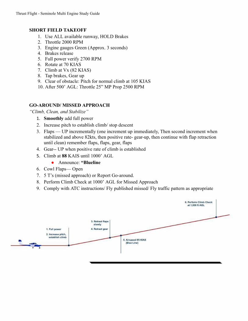
GO-AROUND/ MISSED APPROACH “Climb, Clean, and Stabilize”
1. Smoothly add full power 2. Increase pitch to establish climb/ stop descent 3. Flaps — UP incrementally (one increment up immediately, Then second increment when
stabilized and above 82kts, then positive rate- gear-up, then continue with flap retraction until clean) remember flaps, flaps, gear, flaps
4. Gear-- UP when positive rate of climb is established 5. Climb at 88 KAIS until 1000’ AGL
● Announce: “Blueline 6. Cowl Flaps— Open 7. 5 T’s (missed approach) or Report Go-around. 8. Perform Climb Check at 1000’ AGL for Missed Approach 9. Comply with ATC instructions/ Fly published missed/ Fly traffic pattern as appropriate
Thrust Flight - Seminole Multi Engine Study Guide
PRECISION APPROACH 1. Enroute: Approach should be fully briefed/ NAVaids set/checked/ Instruments checked 2. Slow to 100 KIAS (16” MP) within approx. 5 NM from initial approach fix / or while given vectors to
approach 3. HSI Set and Checked 4. Before Landing Checklist 5. Within 2nm from final approach
1. Throttle to 16” MP 2. Flaps 25 ( Flaps 10 or up on single engine approach) 3. Maintain 88 KIAS , Trim 4. GUMPS check 5. Re-Brief Approach mins and missed approach procedures
6. Gear should be extended when glideslope captured 1. Verify gear down, 3 green, no red, check visually
7. At FAF 1. 5 T’s 2. Announce: “Gear Down, Before Landing Checklist Complete” 3. Descent with approximately 15” MP
8. Announce 100’ above minimums: “100 to go” 9. Decision Altitude, Announce : “Minimum” 10. Flaps—as required on final 11. Airspeed 88 (blueline) until landing is assured 12. Final GUMPS check 13. Follow glideslope down to runway 14. Reduce power smoothly when landing is assured
NON-PRECISION APPROACH 1. En-route: Approach should be fully briefed/ NAVaids set/checked/ Instruments checked 2. Slow to 100 KIAS (16” MP) within approx. 5 nm from initial approach fix / or while given vectors to
approach 3. HSI Set and Checked 4. Before Landing Checklist 5. Within 2 nm from final approach
1. Throttle - 16” MP 2. Flaps - 25 (2 engines), Flaps 10 or up on single engine approach 3. Maintain 88 KIAS, Trim 4. GUMPS check ,Gear - Down , verify 3 green, no red, check visually 5. Re-Brief approach mins and missed approach
6. FAF 1. 5 T’s 2. Announce : “Gear Down, Before Landing Checklist Complete” 3. Descend approx 700 fpm when established, 13” MP, maintain 88 KIAS
7. Announce 100’ from MDA: “100 to go” 8. MDA
1. Announce : “Minimum” 2. Level off at MDA using approx 20” MP
9. Flaps- as required on final

Thrust Flight - Seminole Multi Engine Study Guide
10. Airspeed 88 (blueline) until landing is assured 11. Final GUMPS check 12. Continue stabilize approach to runway 13. Reduce power smoothly when landing is assured
CIRCLING APPROACH Before reaching FAF brief plan for circling approach:
● From MDA circle (left/right) for RWY . Remain within 1.3 nm from RWY. If visual of RWY is lost, execute the missed approach. (turn to parallel approach course and execute published missed)
Continuing from Precision or Non-precision approach 1. Announce 100’ from MDA: “100 to go” 2. MDA
1. Announce: “Minimum” 2. Level off at MDA using approx 20” MP, 88-100 KIAS
3. Commence circling approach procedures, Maintain 88-100 KIAS and stay within 1.5 nm from runway (category B minimums)
4. While turning base still above MDA 5. Announce: “Landing, leaving MDA” before descending below MDA (must be able
to make a stabilized approach to land on base or final before descending below MDA)
6. Flaps—as required 7. Airspeed 88 (blueline) until landing is assured 8. Final GUMPS check 9. Continue stabilize approach to runway (no more than 600 fpm descent) 10. Reduce power smoothly when landing is assured
HOLDING 1. Slow to 100 KIAS holding speed 3 minutes to fix 2. Acquire EFC 3. Hold at 100 KIAS, approx 15” MP, established in hold when passing holding fix, 5 T’s 4. Report altitude and time at holding fix

Thrust Flight - Seminole Multi Engine Study Guide
Section 4:
Emergency Procedures
These are emergency memory/review items only , they do not encompass all the emergency procedures listed in the POH. In any emergency or abnormal condition the POH should be consulted.
MEMORIZE! IN-FLIGHT ENGINE FAILURE
1 Airspeed 88(Blue Line) 2 Mixtures Full FWD 3 Props Full FWD 4 Throttles Full FWD 5 Gear RETRACT 6 Flaps UP 7 Identify Dead Foot 8 Verify/ Throttle CLOSE(Slowly) 9 Troubleshoot “Fix or Feather” If Alt Permits
10 Prop (bad engine) FEATHER 11 Mixture (bad engine) IDLE Cut Off 12 Emergency Checklist Applicable 13 Declare Emergency
After going through the in-flight engine failure flow, a decision will be made to try to fix the dead engine or to immediately feather. (i.e. “fix or feather.”) If an engine is lost below 2000 ft AGL feather the prop on the dead engine. If an engine is lost above 2000 ft AGL and there is sufficient time/ground clearance, “fix” and troubleshoot the dead engine. The zero sideslip condition should be established. (“raise the dead.”) After going through the engine failure memory items always remember to consult the appropriate emergency checklist and declare an emergency.
MEMORIZE! ENGINE FAILURE DURING GROUND ROLL
1 Throttles IDLE 2 Braking MAXIMUM 3 Master/Magnetos OFF
This checklist should be accomplished if an engine failure occurs after rotation with gear down and there is sufficient usable runway remaining to reject takeoff… even if it means rolling off the end of the runway (as briefed prior to takeoff). If an engine fails on takeoff, think: “Abort, Abort, Abort.”

Thrust Flight - Seminole Multi Engine Study Guide
REVIEW
ENGINE TROUBLESHOOT “FIX” ABOVE 2000 AGL Continuing from in-flight engine failure flow.
1 Trim As Req 2 Aux pumps on 3 Magnetos on 4 Engine gauges check 5 Mixtures check
6 Carb heat check 7 Primers locked 8 Fuel selectors on 9 Verify with checklist
10 Secure the dead engine and declare emergency
ENGINE FAILURE-- SECURE INOP ENGINE “FEATHER” BELOW 2000’ AGL Continuing from in-flight engine failure flow.
1 Trim As Req 2 Mixture (inop eng) Idle Cut-Off 3 Fuel Selector (inop eng) Off 4 Aux Fuel Pump (inop eng) Off 5 Magneto (inop eng) Off 6 Alternator Switch Off 6 Cowl Flap (inop eng) Closed 7 Airspeed 88 (Blueline) 8 Electrical Load Monitor 9 Refer to appropriate Checklist
NOTE: The most important aspect of engine failure is the necessity to maintain lateral and directional control. If airspeed is at 56 knots, reduce power on operative engine as required to maintain control
![180 Degrees Pa V2[1]](https://static.fdocuments.us/doc/165x107/554c4880b4c90570648b548e/180-degrees-pa-v21.jpg)