P9 addressing signal_integrity_ in_ew_2015_final
35
Addressing Signal Integrity in Radar and Electronic Warfare Systems 2015 Aerospace Defense Symposium [ Speaker Name ] Keysight Technologies
-
Upload
aamir-habib -
Category
Engineering
-
view
20 -
download
1
Transcript of P9 addressing signal_integrity_ in_ew_2015_final

Addressing Signal Integrity in Radar and Electronic Warfare Systems2015 Aerospace Defense Symposium
[ Speaker Name ] Keysight Technologies

Page
Paper Summary
Increasing data bus rates in today’s Radar and EW systems can lead to electrical impairments, affecting the signal integrity of the transmitted signals. Signal Integrity can be measured and characterized to help design engineers avoid potential problems.
2015 AD Symposium 2

Page 3
Agenda2015 AD Symposium
– What is Signal Integrity?
– What challenges can occur at high data rates?
– Where are the high data rates occurring in Radar/EW applications?
– How do we address those with our solutions?

Page
What is Signal Integrity?
Even digital signals, 0’s and 1’s, are represented by a voltage waveform.
Those digital signals implemented into real systems with PC board traces, connectors, and cables will be subject to analog parametric issues.
Short distances, low bit rates… no problem.
High bit rates, longer distances? Various effects will degrade the signal.
Think Signal Quality…
• Set of measures of the quality of an electrical signal
Signal Integrity (SI)
2015 AD Symposium 4

Channel ResponseSource Signal
Received signal
Signal Integrity is Critical…
2015 AD Symposium 5Page

Page
Transmitter(TX)
Receiver(RX)Channel
0 1 0 1 1 0 0
All transmitted signals shall be received correctly
Beyond some speed everything affects signal integrity
High Speed Drives Signal Integrity
2015 AD Symposium 6

Page
Receiver(RX)Channel
0 1 0 1 1 0 0
All transmitted signals shall be received correctly
Beyond some speed everything affects signal integrity
High Speed Drives Signal Integrity
2015 AD Symposium 7

Page
Transmitter(TX)
Receiver(RX)Channel
0 1 0 1 1 0 0
All transmitted signals shall be received correctly
Beyond some speed everything affects signal integrity
High Speed Drives Signal Integrity
Channel responses of two backplane topologies(1)
2015 AD Symposium 8

Page
Transmitter(TX)
Receiver(RX)Channel
0 1 0 1 1 0 0
All transmitted signals shall be received correctly
Beyond some speed everything affects signal integrity
High Speed Drives Signal Integrity
Channel responses of two backplane topologies(1)
S-Parameter of PCIe channel
2015 AD Symposium 9

Page
Transmitter(TX)
Receiver(RX)Channel
0 1 0 1 1 0 0
All transmitted signals shall be received correctly
Beyond some speed everything affects signal integrity
Channel responses of two backplane topologies(1)
S-Parameter of PCIe channel
High Speed Drives Signal Integrity
2015 AD Symposium 10

Page
Agenda2015 AD Symposium 11
– What is Signal Integrity?
– What challenges can occur at high data rates?
– Where are the high data rates occurring in Radar/EW applications?
– How do we address those with our solutions?

Page
Effects That Can Degrade the Signal
System Performance Power Supply Noise
Material Loss vs Frequency EMI/ Crosstalk
InterconnectionsImpedance TDR
PackageConnector Cable
PCB
ConnectorPackage
PCB
ICIC
PassiveTx ActiveRx
Active
ImpedanceMatching
Channel Skin Effect
2015 AD Symposium 12

Page
Agenda2015 AD Symposium 13
– What is Signal Integrity?
– What challenges can occur at high data rates?
– Where are the high data rates occurring in Radar/EW applications?
– How do we address those with our solutions?

Page
Sample Scenario
#1) Radar Guided Missile Capture and Playback
X-band Radar10 GHz
Target
2015 AD Symposium 14

Page
– Time of Arrival (TOA)
– Angle of Arrival (AOA)
– Frequency (RF)
– Amplitude (PA)
– Pulse Width (PW)
#2) Radar Warning Receiver (PDWs)
AOA
RFPA
PWTOA
Sample Scenario
2015 AD Symposium 15

Page
RF Converter ADCs Spectrum
EstimatorPara
EncoderDigital
Processor
#2) Radar Warning Receiver (PDWs) cont’d
Digital EW Receiver
Digital WordsIF Freq
Sample Scenario
2015 AD Symposium 16

Page
Digital Commercial Off the Shelf (COTS )
• Double data rate DRAM• Class of memory used in computer systems and
embedded systems• ie: Store incoming waveform data for playback
DDR Memory
• Serial high-speed interconnect/link• ie: Interface to stream data from receiving
antenna to processing PC.PCIe
• Serial high-speed interconnect/link• ie: Many applications, wherever you see Ethernet
now.
10 Gb Ethernet
2015 AD Symposium 17

Page
Agenda2015 AD Symposium 18
– What is Signal Integrity?
– What challenges can occur at high data rates?
– Where are the high data rates occurring in Radar/EW applications?
– How do we address those with our solutions?

Page
SI Measurement Needs
Upward trend of bus rates calls for special kind of design engineer.
High-speed interconnects are critical elements of differential channels that must be designed using today’s most powerful analysis and characterization tools.
Both simulation and measurements must be done on DUT and resulting data needs to correlate with each other.
2015 AD Symposium 19

Page
High Speed Digital Design-Flow
20
ComplianceTest
System Design
InterconnectDesign
Analysis Debug
• Build accurate models
• Accurate Simulation
• Refine models & simulations
• Accurate Design Analysis
• Correlation
• Accurate Design Analysis
• Measurement Automation
• Debug• Correlation
• Stress test• Protocol test• Measurement
Automation• Compliance
2015 AD Symposium 20

Page
Channel Simulation with Keysight ADS
– Extremely Fast and Accurate
– Waveforms/BER/Eye Diagrams.
– Electrical & Optical S-parameters from EM/VNA/TDR/LCA
System
Design
2015 AD Symposium 21

Page
TDR/TDT
Time Domain Reflectometry (TDR)
– Example measurements:• Impedance - locate the position and nature
of each discontinuity• Propagation/Time delay• Excess Reactance
(Capacitance or Inductance)
Time Domain Reflectometry (TDR)
Incident wave
Reflected wave
DUT- PCB- Connector- Cable- Interconnect
Step Generator
Sampler
TDR (impedance Profile)S11 (Return Loss)
TDR Module
Time Domain Reflectometry (TDR)
Incident wave
Reflected wave
DUT- PCB- Connector- Cable- Interconnect
Step Generator
Sampler
TDR (impedance Profile)TDR Module
Time Domain Transmission (TDT)
Incident wave
Reflected wave
DUT- PCB- Connector- Cable- Interconnect
Step Generator
Sampler
TDR S11
TDR Module
Transmitted wave
Step Generator
Sampler
TDR or RX onlyModule
TDT (Step Response)
Time Domain Transmission (TDT)
Example Measurements:• Step Response• Propagation/Time delay• Rise time degradation • Near-end crosstalk (NEXT)• Far-end crosstalk (FEXT)• Skew
Interconnect
Design
2015 AD Symposium 22

Page
Physical Layer Test System
Industry Standard for High Speed Digital Interconnect Analysis• Calibrate, measure and characterize
backplanes, PCBs, cables, connectors and IC packages
• Leverage multi-domain analysis to use one test system for all time domain, frequency domain, eye diagram, and RLCG analysis
• Extract full 4-port s-parameters of fixtures from a simple reflection measurement
• Commonly used for multi-port/channel. (Up to 32)
Interconnect
Design
2015 AD Symposium 23
Page
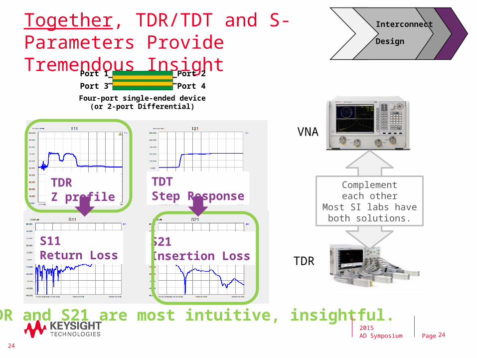
Together, TDR/TDT and S-Parameters Provide Tremendous Insight
TDR and S21 are most intuitive, insightful.
TDRZ profile
TDTStep Response
S11Return Loss
S21Insertion Loss
24
Four-port single-ended device(or 2-port Differential)
Port 1
Port 3
Port 2
Port 4
Complementeach other
Most SI labs have both solutions.
VNA
TDR
Interconnect
Design
2015 AD Symposium 24

Page
Eye Diagram
• The easiest way to get an overall idea of the quality of the serial signal
• Measurement commonly made on an Oscilloscope
• Eye Diagram is the superposition of all combination of bit sequences
• Multiple cases combined form the Eye
• Trigger on Clock signal (if available) as the rough first pass to build Eye Diagram
101 Sequence 011 Sequence Overlay of all combinations
Analysis
Debug
Infiniium 90000 X-Series
2015 AD Symposium 25

Page
What Closes the Eye
• Eye “closing” indicates variations in both voltage levels of bits and timing issues.
• Various SI issues can cause the eye to close.
- Attenuation due to Material Loss or Channel Skin Effect
- Noise from power supply
- Glitches from reflections or other data lines (Impedance mismatches, EMI/X-talk)
- System Bandwidth limitations
Analysis
Debug
2015 AD Symposium 26

Analysis
Debug
Eye Diagrams – Simulation vs. Measurement
5 Gb/s 10 Gb/s
5 Gb/s 10 Gb/s
Simulation Simulation
MeasurementMeasurement
- Simulation using saved .s4p file
SIMULATION
MEASUREMENT
2015 AD Symposium 27Page
- Good correlation between simulation and measurement- As expected, edge speeds at 10 Gbps are much slower (lack of 3rd harmonic content)

Page
Bit Error Ratio Tester (BERT)
J-BERT M8020A
Analysis
Debug
• Primary quality metric of a transmission link.
• Measures number of failed bits at receiver compared to total number of transmitted bits.
• Common BER level is 10-12
Pattern Generator
Error Detector
2015 AD Symposium 28

Page
Keysight’s solution set for high-speed digital test is a combination of instrumentation and broad expertise built on our ongoing involvement with industry experts. By sharing our latest experiences, we can help anticipate challenges and accelerate your ability to create products you’ll be proud of.
Advanced Design System
(ADS) and EMPro
N1930B Physical Layer Test
System (PLTS)
Bit Error Ratio Testers (BERTs)
ENA-TDR
Infiniium 90000 X-Series
AXIe-based Logic
Analyzer Module86100D Infiniium
DCA-X
Insights For Your Best Design With Keysight
2015 AD Symposium 29

Page
Top 3 Take-Aways
At high data rates, there are various effects that can distort the integrity of a signal that you are trying to transmit.
These high data rates can be found in many Radar and EW applications and
will only continue to grow.
Keysight has the solutions and expertise to address these Signal Integrity
challenges from beginning to end.
2015 AD Symposium 30

Questions?

Page
Back Up (Resources)
2015 AD Symposium 32

Page
– Signal Integrity Keysight Homepage
– Signal Integrity YouTube Videos
– Signal Integrity
• Basic Principles of Signal Integrity and how to combat those issues
• Signal Integrity Characterization techniques (Book)
• New Calibration Method Simplifies Measurements of Fixtured Devices
2015 AD Symposium 33
Resources (Presentations, Application Notes, Web links)

Page
Resources (Presentations, Application Notes, Web links)
– Design/Simulation(EEsof)
• SI Q&A collections using Keysight ADS
• Tutorials in SI Webcasts library
• EEsof High Speed Digital Internal site
• Signal Integrity Blog
• Presentations
- TDR/TDT Simulation skills (June, 2014)
- EMI/EMC Analysis for HSD Designs (July, 2014)
- How to optimize your SerDes design during pre-layout phase (Sept, 2014)
2015 AD Symposium 34

Page
Resources (Presentations, Application Notes, Web links)
– TDR/PLTS
• Breakthrough Developments in TDR/TDT Measurement Technology (June, 2014)
• PLTS 2015 Software Technical Overview
– Oscilloscopes
• Measure your Signal, not your Measurement System
• How Understanding and Characterizing an Oscilloscope Impacts Signal Integrity
• Perform Deep Real-Time Eye Analysis
• Practical Guide to Making Advanced Jitter Measurements
• Evaluating Oscilloscope Signal Integrity (Application Note)
2015 AD Symposium 35