P25 EOM - Wilden · PDF fileP25 WIL-11020-E-03 REPLACES WIL-11020-E-02 EOM Advance your...
22
P25 WIL-11020-E-03 REPLACES WIL-11020-E-02 EOM Advance your process Engineering Operation & Maintenance Advanced ™ Series PLASTIC Pumps
-
Upload
hoangtuyen -
Category
Documents
-
view
232 -
download
1
Transcript of P25 EOM - Wilden · PDF fileP25 WIL-11020-E-03 REPLACES WIL-11020-E-02 EOM Advance your...

P25
WIL-11020-E-03REPLACES WIL-11020-E-02
EOM
A d v a n c e y o u r p r o c e s s
E n g i n e e r i n g O p e r a t i o n &M a i n t e n a n c eAdvanced™ Series PLASTIC Pumps

T A B L E O F C O N T E N T S
SECTION 1 CAUTIONS—READ FIRST! . . . . . . . . . . . . . . . . . . . . . . . . . . . . . . . . . . . . . . . . . . . . . .1
SECTION 2 WILDEN PUMP DESIGNATION SYSTEM . . . . . . . . . . . . . . . . . . . . . . . . . . . . . . . . .2
SECTION 3 HOW IT WORKS—PUMP & AIR DISTRIBUTION SYSTEM . . . . . . . . . . . . . . . .3
SECTION 4 DIMENSIONAL DRAWING . . . . . . . . . . . . . . . . . . . . . . . . . . . . . . . . . . . . . . . . . . . . . .4
SECTION 5 PERFORMANCE
A. Performance Curves
PTFE-Fitted . . . . . . . . . . . . . . . . . . . . . . . . . . . . . . . . . . . . . . . . . . . . . . . . . . . . . . . . . .5
B. Suction Lift Curve . . . . . . . . . . . . . . . . . . . . . . . . . . . . . . . . . . . . . . . . . . . . . . . . . . . . . .5
SECTION 6 SUGGESTED INSTALLATION, OPERATION & TROUBLESHOOTING . . . . . . . .6
SECTION 7 DISASSEMBLY / REASSEMBLY . . . . . . . . . . . . . . . . . . . . . . . . . . . . . . . . . . . . . . . . .9
SECTION 8 EXPLODED VIEW & PARTS LISTING
PTFE-Fitted . . . . . . . . . . . . . . . . . . . . . . . . . . . . . . . . . . . . . . . . . . . . . . . . . . . . . . . . . . . . .16
SECTION 9 ELASTOMER OPTIONS . . . . . . . . . . . . . . . . . . . . . . . . . . . . . . . . . . . . . . . . . . . . . . . . .18

CAUTION: Do not apply compressed air to the exhaust port — pump will not function.
CAUTION: Do not over-lubricate air supply — excess lubrication will reduce pump performance. Pump is pre-lubed.
TEMPERATURE LIMITS:
Polypropylene 0°C to 79.4°C 32°F to 175°F PVDF –12.2°C to 107.2°C 10°F to 225°F Neoprene –17.8°C to 93.3°C 0°F to 200°F Buna-N –12.2°C to 82.2°C 10°F to 180°F EPDM –51.1°C to 137.8°C –60°F to 280°F Viton® –40°C to 176.7°C –40°F to 350°F Wil-Flex™ –40°C to 107.2°C –40°F to 225°F Sanifl ex™ –28.9°C to 104.4°C –20°F to 220°F Polyurethane –12.2°C to 65.6°C 10°F to 150°F
Tetra-Flex™ PTFE w/Neoprene Backed 4.4°C to 107.2°C 40°F to 225°F
Tetra-Flex™ PTFE w/EPDM Backed -10°C to 137.8°C 14°F to 280°F
PTFE 4.4°C to 104.4°C 40°F to 220°F
CAUTION: When choosing pump materials, be sure to check the temperature limits for all wetted components. Example: Viton® has a maximum limit of 176.7°C (350°F) but polypropylene has a maximum limit of only 79.4°C (175°F).
CAUTION: Maximum temperature limits are based upon mechanical stress only. Certain chemicals will signifi cantly reduce maximum safe operating temperatures. Consult Chemical Resistance Guide (E4) for chemical compatibility and temperature limits.
WARNING: Prevention of static sparking — If static sparking occurs, fi re or explosion could result. Pump, valves, and containers must be grounded to a proper grounding point when handling fl ammable fl uids and whenever discharge of static electricity is a hazard.
CAUTION: Do not exceed 8.6 bar (125 psig) air supply pressure.
CAUTION: The process fl uid and cleaning fl uids must be chemically compatible with all wetted pump components (see E4).
CAUTION: Pumps should be thoroughly fl ushed before installing into process lines. FDA and USDA approved pumps should be cleaned and/or sanitized before being used.
CAUTION: Always wear safety glasses when operating pump. If diaphragm rupture occurs, material being pumped may be forced out air exhaust.
CAUTION: Before any maintenance or repair is attempted, the compressed air line to the pump should be disconnected and all air pressure allowed to bleed from pump. Disconnect all intake, discharge and air lines. Drain the pump by turning it upside down and allowing any fl uid to fl ow into a suitable container.
CAUTION: Blow out air line for 10 to 20 seconds before attaching to pump to make sure all pipeline debris is clear. Use an in-line air fi lter. A 5µ (micron) air fi lter is recommended.
NOTE: Before starting disassembly, mark a line from each liquid chamber to its corresponding air chamber. This line will assist in proper alignment during reassembly.
CAUTION: Pro-Flo® pumps cannot be used in submersible applications. Pro-Flo V™ is available in both submersible and non-submersible options. Do not use non-submersible Pro-Flo V™ models in submersible applications. Turbo-Flo™ pumps can be used in submersible applications.
CAUTION: Tighten all hardware prior to installation.
WIL-11020-E-03 1 WILDEN PUMP & ENGINEERING, LLC
S e c t i o n 1
C A U T I O N S — R E A D F I R S T !
NOTE: MOST ELASTOMERIC MATERIALS USE COLORED DOTS FOR IDENTIFICATION
Viton® is a registered trademark of Dupont Dow Elastomers.
WILDEN PUMP & ENGINEERING, LLC 2 WIL-11020-E-03
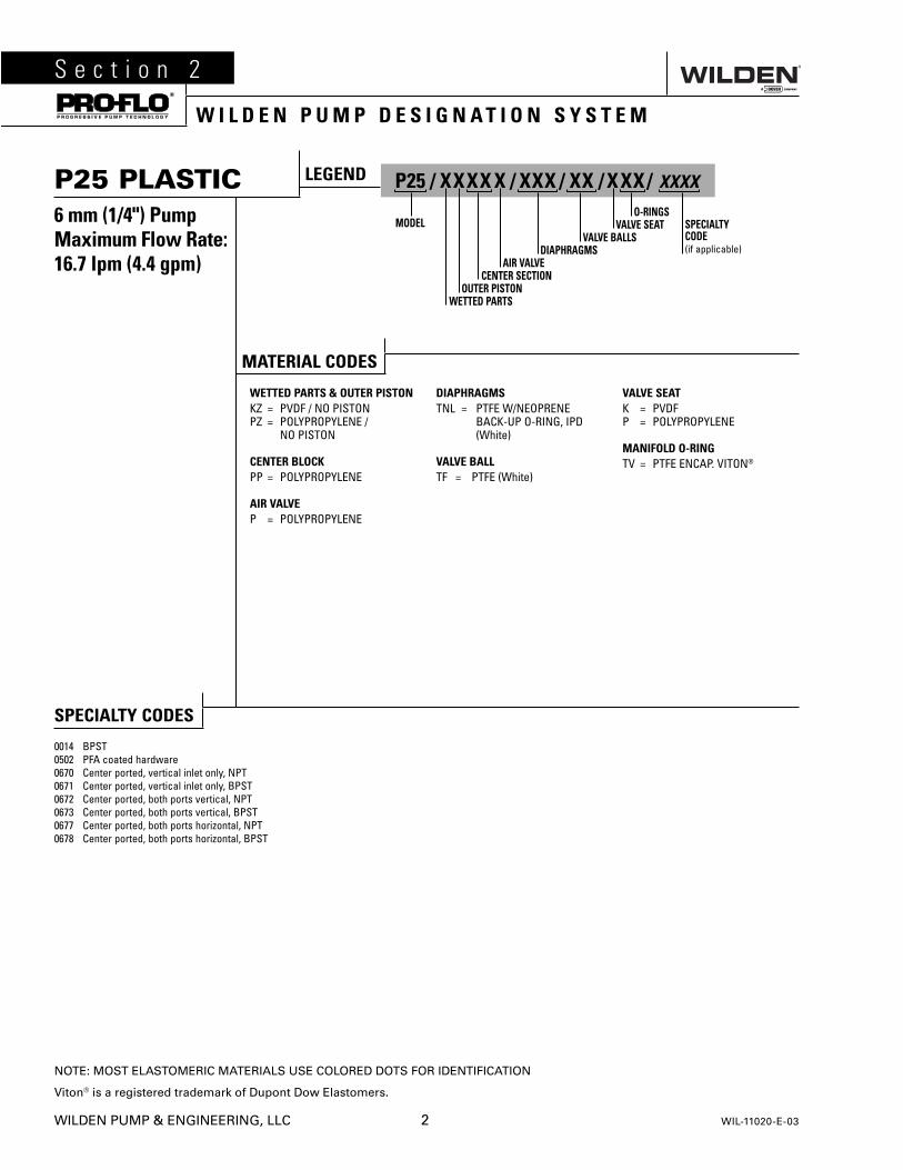
P25 PLASTIC6 mm (1/4") PumpMaximum Flow Rate:16.7 lpm (4.4 gpm)
S e c t i o n 2
W I L D E N P U M P D E S I G N A T I O N S Y S T E M
SPECIALTY CODES
0014 BPST0502 PFA coated hardware0670 Center ported, vertical inlet only, NPT0671 Center ported, vertical inlet only, BPST0672 Center ported, both ports vertical, NPT0673 Center ported, both ports vertical, BPST0677 Center ported, both ports horizontal, NPT0678 Center ported, both ports horizontal, BPST
LEGEND P25 / XXXX X / XXX / XX / XXX / XXXX
O-RINGSMODEL VALVE SEAT
VALVE BALLSDIAPHRAGMS
AIR VALVECENTER SECTION
OUTER PISTONWETTED PARTS
SPECIALTYCODE(if applicable)
MATERIAL CODES
WETTED PARTS & OUTER PISTONKZ = PVDF / NO PISTONPZ = POLYPROPYLENE / NO PISTON
CENTER BLOCKPP = POLYPROPYLENE
AIR VALVEP = POLYPROPYLENE
DIAPHRAGMSTNL = PTFE W/NEOPRENE BACK-UP O-RING, IPD (White)
VALVE BALLTF = PTFE (White)
VALVE SEATK = PVDFP = POLYPROPYLENE
MANIFOLD O-RINGTV = PTFE ENCAP. VITON®
S e c t i o n 3
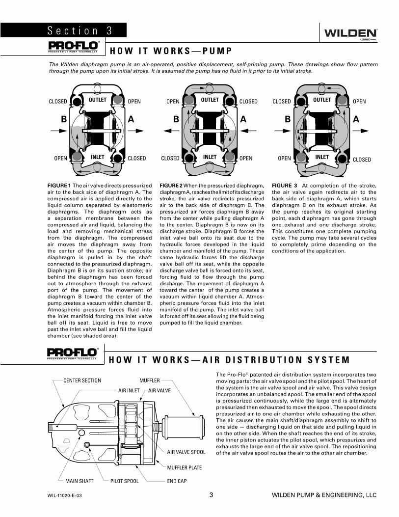
H O W I T W O R K S — P U M P The Wilden diaphragm pump is an air-operated, positive displacement, self-priming pump. These drawings show fl ow pattern through the pump upon its initial stroke. It is assumed the pump has no fl uid in it prior to its initial stroke.
FIGURE 1 The air valve directs pressurized air to the back side of diaphragm A. The compressed air is applied directly to the liquid column separated by elastomeric diaphragms. The diaphragm acts as a separation membrane between the compressed air and liquid, balancing the load and removing mechanical stress from the diaphragm. The compressed air moves the diaphragm away from the center of the pump. The opposite diaphragm is pulled in by the shaft connected to the pressurized diaphragm. Diaphragm B is on its suction stroke; air behind the diaphragm has been forced out to atmosphere through the exhaust port of the pump. The movement of diaphragm B toward the center of the pump creates a vacuum within chamber B. Atmospheric pressure forces fl uid into the inlet manifold forcing the inlet valve ball off its seat. Liquid is free to move past the inlet valve ball and fi ll the liquid chamber (see shaded area).
FIGURE 2 When the pressurized diaphragm, diaphragm A, reaches the limit of its discharge stroke, the air valve redirects pressurized air to the back side of diaphragm B. The pressurized air forces diaphragm B away from the center while pulling diaphragm A to the center. Diaphragm B is now on its discharge stroke. Diaphragm B forces the inlet valve ball onto its seat due to the hydraulic forces developed in the liquid chamber and manifold of the pump. These same hydraulic forces lift the discharge valve ball off its seat, while the opposite discharge valve ball is forced onto its seat, forcing fl uid to fl ow through the pump discharge. The movement of diaphragm A toward the center of the pump creates a vacuum within liquid chamber A. Atmos-pheric pressure forces fl uid into the inlet manifold of the pump. The inlet valve ball is forced off its seat allowing the fl uid being pumped to fi ll the liquid chamber.
FIGURE 3 At completion of the stroke, the air valve again redirects air to the back side of diaphragm A, which starts diaphragm B on its exhaust stroke. As the pump reaches its original starting point, each diaphragm has gone through one exhaust and one discharge stroke. This constitutes one complete pumping cycle. The pump may take several cycles to completely prime depending on the conditions of the application.
The Pro-Flo® patented air distribution system incorporates two moving parts: the air valve spool and the pilot spool. The heart of the system is the air valve spool and air valve. This valve design incorporates an unbalanced spool. The smaller end of the spool is pressurized continuously, while the large end is alternately pressurized then exhausted to move the spool. The spool directs pressurized air to one air chamber while exhausting the other. The air causes the main shaft/diaphragm assembly to shift to one side — discharging liquid on that side and pulling liquid in on the other side. When the shaft reaches the end of its stroke, the inner piston actuates the pilot spool, which pressurizes and exhausts the large end of the air valve spool. The repositioning of the air valve spool routes the air to the other air chamber.
H O W I T W O R K S — A I R D I S T R I B U T I O N S Y S T E M
WIL-11020-E-03 3 WILDEN PUMP & ENGINEERING, LLC

DIMENSIONS
ITEM METRIC (mm) STANDARD (inch)
A 173 6.8B 102 4.0C 25 1.0D 157 6.2E 127 5.0F 173 6.8G 61 2.4H 99 3.9J 53 2.1K 81 3.2L 10 0.4M 5 0.2N 150 5.9
P25 Advanced™ Plastic
S e c t i o n 4
D I M E N S I O N A L D R A W I N G S
WILDEN PUMP & ENGINEERING, LLC 4 WIL-11020-E-03
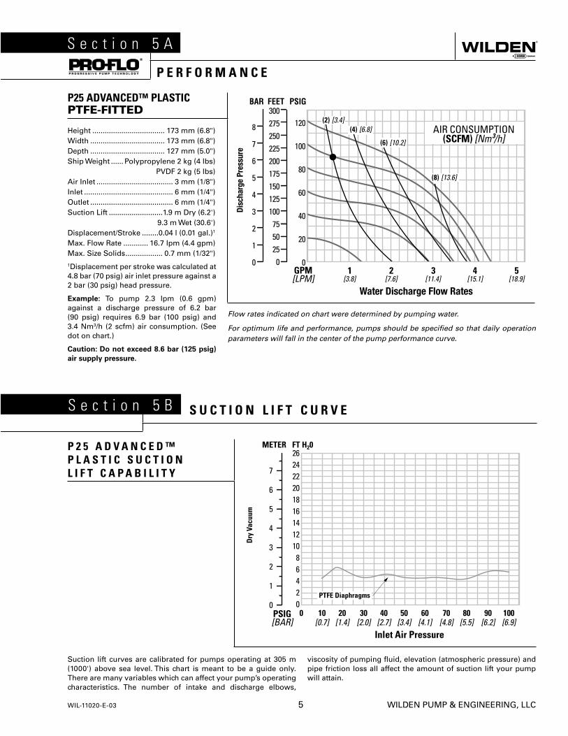
Suction lift curves are calibrated for pumps operating at 305 m (1000') above sea level. This chart is meant to be a guide only. There are many variables which can affect your pump’s operating characteristics. The number of intake and discharge elbows,
viscosity of pumping fl uid, elevation (atmospheric pressure) and pipe friction loss all affect the amount of suction lift your pump will attain.
P 2 5 A D V A N C E D ™ P L A S T I C S U C T I O N L I F T C A P A B I L I T Y
P25 ADVANCED™ PLASTICPTFE-FITTED
Flow rates indicated on chart were determined by pumping water.
For optimum life and performance, pumps should be specifi ed so that daily operation parameters will fall in the center of the pump performance curve.
Height ................................... 173 mm (6.8")Width .................................... 173 mm (6.8")Depth .................................... 127 mm (5.0")Ship Weight ...... Polypropylene 2 kg (4 lbs) PVDF 2 kg (5 lbs)Air Inlet ..................................... 3 mm (1/8")Inlet ........................................... 6 mm (1/4")Outlet ........................................ 6 mm (1/4")Suction Lift ..........................1.9 m Dry (6.2') 9.3 m Wet (30.6')Displacement/Stroke ........0.04 l (0.01 gal.)1
Max. Flow Rate ............ 16.7 lpm (4.4 gpm)Max. Size Solids .................. 0.7 mm (1/32")1Displacement per stroke was calculated at 4.8 bar (70 psig) air inlet pressure against a 2 bar (30 psig) head pressure.
Example: To pump 2.3 lpm (0.6 gpm) against a discharge pressure of 6.2 bar (90 psig) requires 6.9 bar (100 psig) and 3.4 Nm3/h (2 scfm) air consumption. (See dot on chart.)
Caution: Do not exceed 8.6 bar (125 psig)
air supply pressure.
S e c t i o n 5 A
P E R F O R M A N C E
S e c t i o n 5 B S U C T I O N L I F T C U R V E
WIL-11020-E-03 5 WILDEN PUMP & ENGINEERING, LLC

WILDEN PUMP & ENGINEERING, LLC 6 WIL-11020-E-03
S e c t i o n 6
S U G G E S T E D I N S T A L L A T I O NWilden pumps are designed to meet the performance requirements of even the most demanding pumping applications. They have been designed and manufactured to the highest standards and are available in a variety of liquid path materials to meet your chemical resistance needs. Refer to the performance section of this manual for an in-depth analysis of the performance characteristics of your pump. Wilden offers the widest variety of elastomer options in the industry to satisfy temperature, chemical compatibility, abrasion resistance and fl ex concerns.
The suction pipe size should be at least the equivalent or larger than the diameter size of the suction inlet on your Wilden pump. The suction hose must be non-collapsible, reinforced type as these pumps are capable of pulling a high vacuum. Discharge piping should also be the equivalent or larger than the diameter of the pump discharge which will help reduce friction losses. It is critical that all fi ttings and connections are airtight or a reduction or loss of pump suction capability will result.
INSTALLATION: Months of careful planning, study, and selection efforts can result in unsatisfactory pump performance if installation details are left to chance.
Premature failure and long term dissatisfaction can be avoided if reasonable care is exercised throughout the installation process.
LOCATION: Noise, safety, and other logistical factors usually dictate where equipment will be situated on the production fl oor. Multiple installations with confl icting requirements can result in congestion of utility areas, leaving few choices for additional pumps.
Within the framework of these and other existing conditions, every pump should be located in such a way that six key factors are balanced against each other to maximum advantage.
ACCESS: First of all, the location should be accessible. If it’s easy to reach the pump, maintenance personnel will have an easier time carrying out routine inspections and adjustments. Should major repairs become necessary, ease of access can play a key role in speeding the repair process and reducing total downtime.
AIR SUPPLY: Every pump location should have an air line large enough to supply the volume of air necessary to achieve the desired pumping rate. Use air pressure up to a maximum of 8.6 bar (125 psig) depending on pumping requirements.
For best results, the pumps should use a 5µ (micron) air fi lter, needle valve and regulator. The use of an air fi lter before the pump will ensure that the majority of any pipeline contaminants will be eliminated.
SOLENOID OPERATION: When operation is controlled by a solenoid valve in the air line, three-way valves should be used. This valve allows trapped air between the valve and the pump to bleed off which improves pump performance. Pumping volume can be estimated by counting the number of strokes per minute and then multiplying the fi gure by the displacement per stroke.
MUFFLER: Sound levels are reduced below OSHA
specifi cations using the standard Wilden muffl er. Other muffl ers can be used to further reduce sound levels, but they usually reduce pump performance.
ELEVATION: Selecting a site that is well within the pump’s dynamic lift capability will assure that loss-of-prime issues will be eliminated. In addition, pump effi ciency can be adversely affected if proper attention is not given to site location.
PIPING: Final determination of the pump site should not be made until the piping challenges of each possible location have been evaluated. The impact of current and future installations should be considered ahead of time to make sure that inadvertent restrictions are not created for any remaining sites.
The best choice possible will be a site involving the shortest and straightest hook-up of suction and discharge piping. Unnecessary elbows, bends, and fi ttings should be avoided. Pipe sizes should be selected to keep friction losses within practical limits. All piping should be supported independently of the pump. In addition, the piping should be aligned to avoid placing stress on the pump fi ttings.
Flexible hose can be installed to aid in absorbing the forces created by the natural reciprocating action of the pump. If the pump is to be bolted down to a solid location, a mounting pad placed between the pump and the foundation will assist in minimizing pump vibration. Flexible connections between the pump and rigid piping will also assist in minimizing pump vibration. If quick-closing valves are installed at any point in the discharge system, or if pulsation within a system becomes a problem, a surge suppressor (SD Equalizer®) should be installed to protect the pump, piping and gauges from surges and water hammer.
If the pump is to be used in a self-priming application, make sure that all connections are airtight and that the suction lift is within the model’s ability. Note: Materials of construction and elastomer material have an effect on suction lift parameters. Please refer to the performance section for specifi cs.
When pumps are installed in applications involving fl ooded suction or suction head pressures, a gate valve should be installed in the suction line to permit closing of the line for pump service.
Pumps in service with a positive suction head are most effi cient when inlet pressure is limited to 0.5–0.7 bar (7–10 psig). Premature diaphragm failure may occur if positive suction is 0.7 bar (10 psig) and higher.
SUBMERSIBLE APPLICATIONS: Pro-Flo V™ pumps can be used for submersible applications, when using the Pro-Flo V™ submersible option. Turbo-Flo™ pumps can also be used for submersible applications.
NOTE: Pro-Flo® and Accu-Flo™ pumps are not submersible.
ALL WILDEN PUMPS ARE CAPABLE OF PASSING SOLIDS. A STRAINER SHOULD BE USED ON THE PUMP INTAKE TO ENSURE THAT THE PUMP'S RATED SOLIDS CAPACITY IS NOT EXCEEDED.
CAUTION: DO NOT EXCEED 8.6 BAR (125 PSIG) AIR SUPPLY PRESSURE.
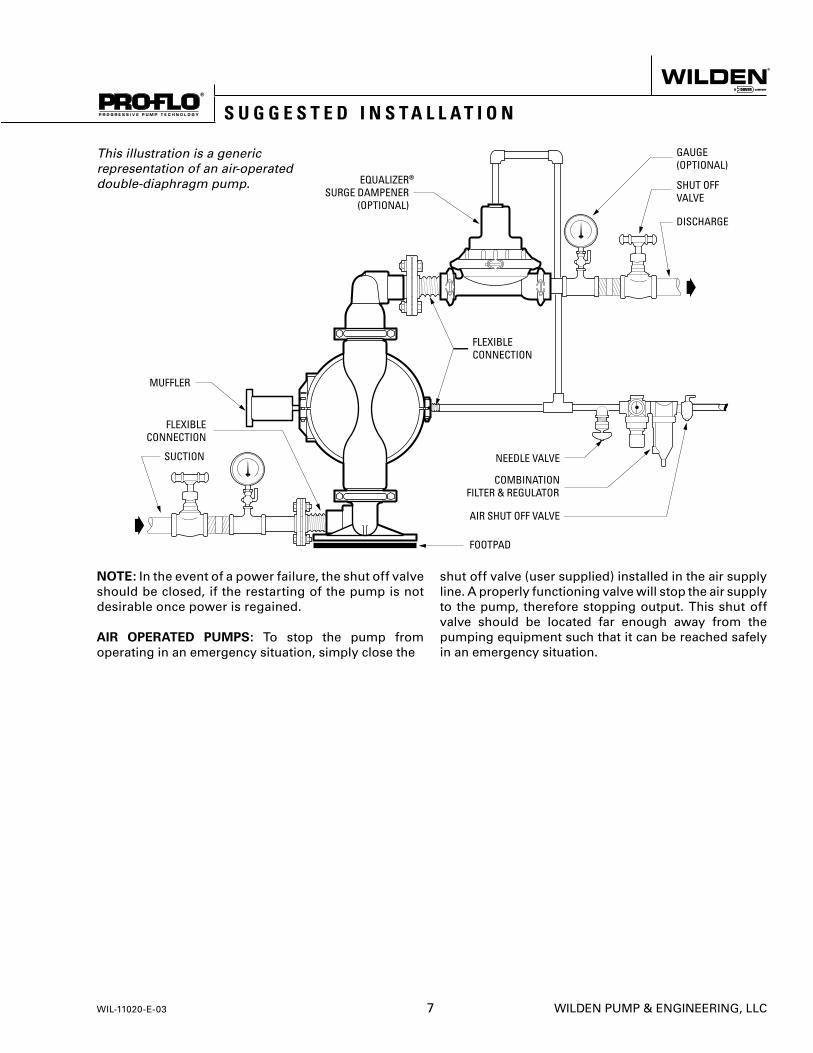
NOTE: In the event of a power failure, the shut off valve should be closed, if the restarting of the pump is not desirable once power is regained.
AIR OPERATED PUMPS: To stop the pump from operating in an emergency situation, simply close the
shut off valve (user supplied) installed in the air supply line. A properly functioning valve will stop the air supply to the pump, therefore stopping output. This shut off valve should be located far enough away from the pumping equipment such that it can be reached safely in an emergency situation.
This illustration is a generic representation of an air-operated double-diaphragm pump.
WIL-11020-E-03 7 WILDEN PUMP & ENGINEERING, LLC
S U G G E S T E D I N S T A L L A T I O N

T R O U B L E S H O O T I N G
WILDEN PUMP & ENGINEERING, LLC 8 WIL-11020-E-03
For best results, the pumps should use an air fi lter and regulator. The use of an air fi lter before the pump will insure that the majority of any pipeline contaminants will be eliminated. The P25 Advanced™ plastic is permanently lubricated and does not require in-line lubrication. Additional lubrication will not damage the pump, however if the pump is heavily lubricated by an external source, the pump’s internal lubrication may be washed away. If the pump is then moved to a non-lubricated location, it may need to be disassembled and re-lubricated as described in the ASSEMBLY/ DISASSEMBLY INSTRUCTIONS.
Pump discharge rate can be controlled by limiting the volume and/or pressure of the air supply to the pump (preferred method). A regulator is used to regulate air pressure. A needle valve is used to regulate air volume. Pump discharge rate can also be controlled by throttling the pump discharge by installing a valve in the discharge line of the pump. This is useful when the need exists to control the pump from a remote
location. When the pump discharge pressure equals or exceeds the air supply pressure, the pump will stop; no bypass or pressure relief valve is needed, and pump damage will not occur. When operation is controlled by a solenoid valve in the air line, two-way or three-way valves may be used. Pumping volume can be set by counting the number of strokes per minute.
INSPECTIONS: Periodic inspections have been found to offer the best means for preventing unscheduled pump downtime. Personnel familiar with the pump’s construction and service should be informed of any abnormalities that are detected during operation.
RECORDS: When service is required, a record should be made of all necessary repairs and replacements. Over a period of time, such records can become a valuable tool for predicting and preventing future maintenance problems and unscheduled downtime. In addition, accurate records make it possible to identify pumps that are poorly suited to their applications.
S U G G E S T E D O P E R A T I O N & M A I N T E N A N C E
Pump will not run or runs slowly.
1. Ensure that the air inlet pressure is at least 0.3 Bar (5 psig) above startup pressure and that the differential pressure (the difference between air inlet and liquid discharge pressures) is not less than 0.7 Bar (10 psig).
2. Check air inlet fi lter for debris (see recommended installation).
3. Check for extreme air leakage (blow by) which would indicate worn seals/bores in the air valve, pilot spool, main shaft.
4. Disassemble pump and check for obstructions in the air passageways or objects which would obstruct the movement of internal parts.
5. Check for sticking ball check valves. If material being pumped is not compatible with pump elastomers, swelling may occur. Replace ball check valves and seals with proper elastomers. Also, as the check valve balls wear out, they become smaller and can become stuck in the seats. In this case, replace balls and seats.
6. Check for broken inner piston which will cause the air valve spool to be unable to shift.
7. Remove plug from pilot spool exhaust.
Pump runs but little or no product fl ows.
1. Check for pump cavitation; slow pump speed down to allow thick material to fl ow into liquid chambers.
2. Verify that vacuum required to lift liquid is not greater than the vapor pressure of the material being pumped (cavitation).
3. Check for sticking ball check valves. If material being pumped is not compatible with pump elastomers, swelling may occur. Replace ball check valves and seats with proper elastomers. Also, as the check valve balls wear out, they become smaller and can become stuck in the seats. In this case, replace balls and seats.
Pump air valve freezes.
1. Check for excessive moisture in compressed air. Either install a dryer or hot air generator for compressed air. Alternatively, a coalescing fi lter may be used to remove the water from the compressed air in some applications.
Air bubbles in pump discharge.
1. Check for ruptured diaphragm.
2. Check tightness of outer pistons (refer to Section 7).
3. Check tightness of fasteners and integrity of o-rings and seals, especially at intake manifold.
4. Ensure pipe connections are airtight.
Product comes out air exhaust.
1. Check for diaphragm rupture.
2. Check tightness of outer pistons to shaft.
T O O L S R E Q U I R E D
• 7/16" Wrench or Socket for Rubber-Fitted
• 3/8" Wrench
CAUTION Before any maintenance or repair is attempted, the compressed air line to the pump should be disconnected and all air pressure allowed to bleed from pump. Disconnect all intake, discharge, and air lines. Drain the pump by turning it upside down and allowing any fl uid to fl ow into a suitable container. Wetted fl ushing of parts may be required prior to handling.
To expedite parts ordering, please fi nd an exploded view of the P25 model at the back of this manual.
PLEASE read all directions before starting disassembly.
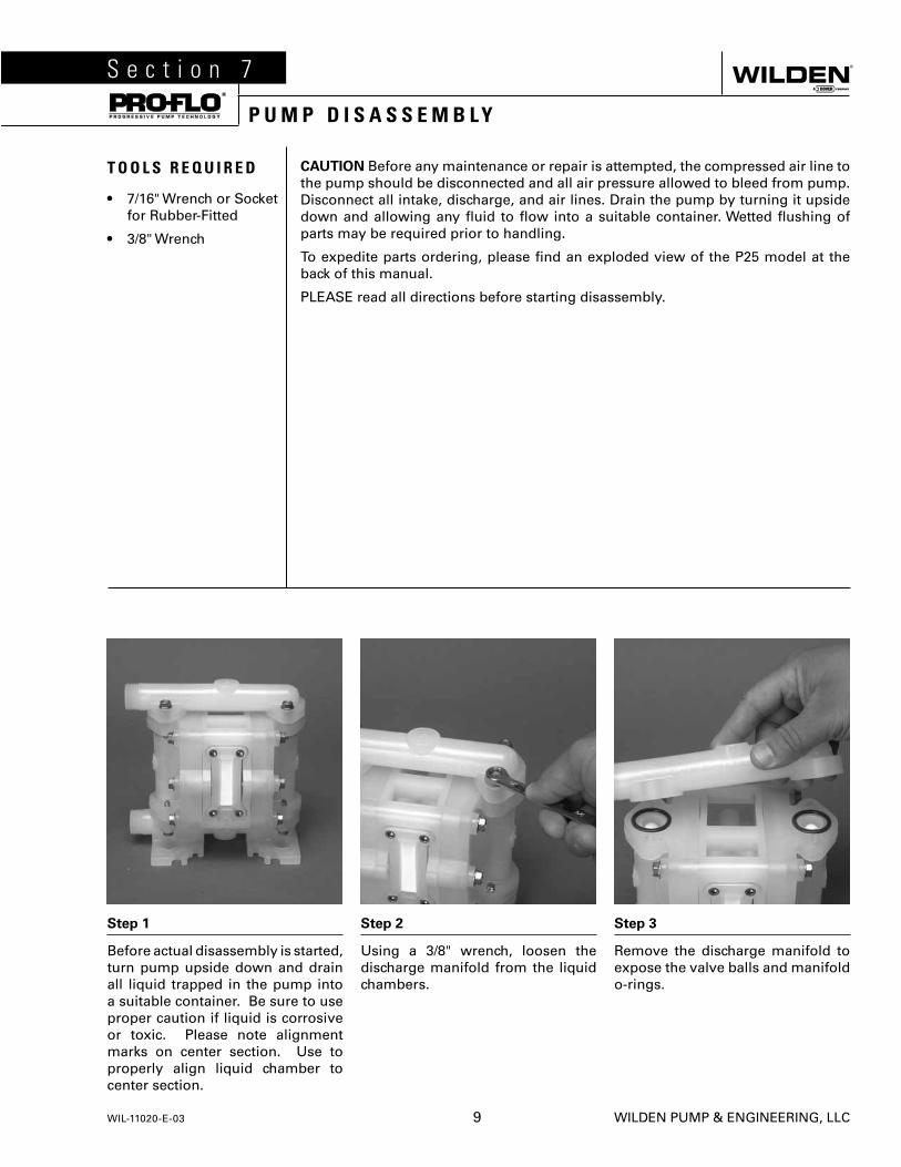
Step 1
Before actual disassembly is started, turn pump upside down and drain all liquid trapped in the pump into a suitable container. Be sure to use proper caution if liquid is corrosive or toxic. Please note alignment marks on center section. Use to properly align liquid chamber to center section.
Step 2
Using a 3/8" wrench, loosen the discharge manifold from the liquid chambers.
Step 3
Remove the discharge manifold to expose the valve balls and manifold o-rings.
S e c t i o n 7
P U M P D I S A S S E M B L Y
WIL-11020-E-03 9 WILDEN PUMP & ENGINEERING, LLC
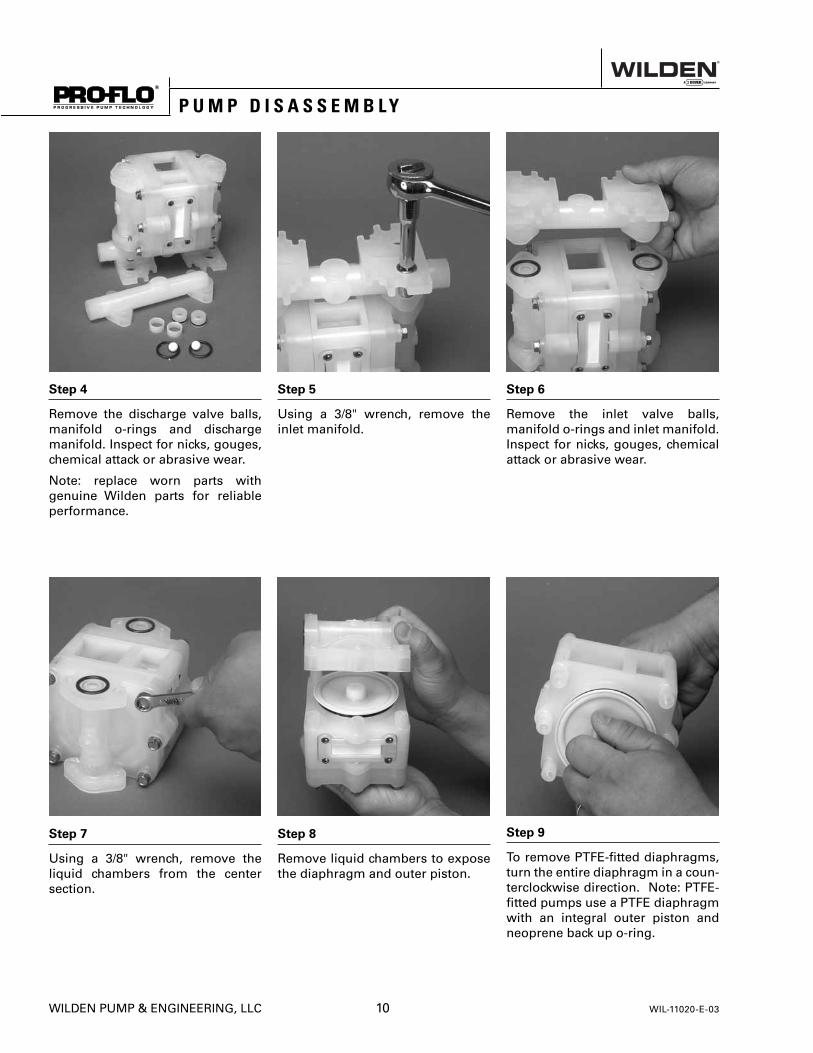
Step 4
Remove the discharge valve balls, manifold o-rings and discharge manifold. Inspect for nicks, gouges, chemical attack or abrasive wear.
Note: replace worn parts with genuine Wilden parts for reliable performance.
Step 5
Using a 3/8" wrench, remove the inlet manifold.
Step 6
Remove the inlet valve balls, manifold o-rings and inlet manifold. Inspect for nicks, gouges, chemical attack or abrasive wear.
Step 7
Using a 3/8" wrench, remove the liquid chambers from the center section.
Step 8
Remove liquid chambers to expose the diaphragm and outer piston.
Step 9
To remove PTFE-fi tted dia phragms, turn the entire diaphragm in a coun-terclockwise direction. Note: PTFE-fi tted pumps use a PTFE diaphragm with an integral outer piston and neoprene back up o-ring.
P U M P D I S A S S E M B L Y
WILDEN PUMP & ENGINEERING, LLC 10 WIL-11020-E-03
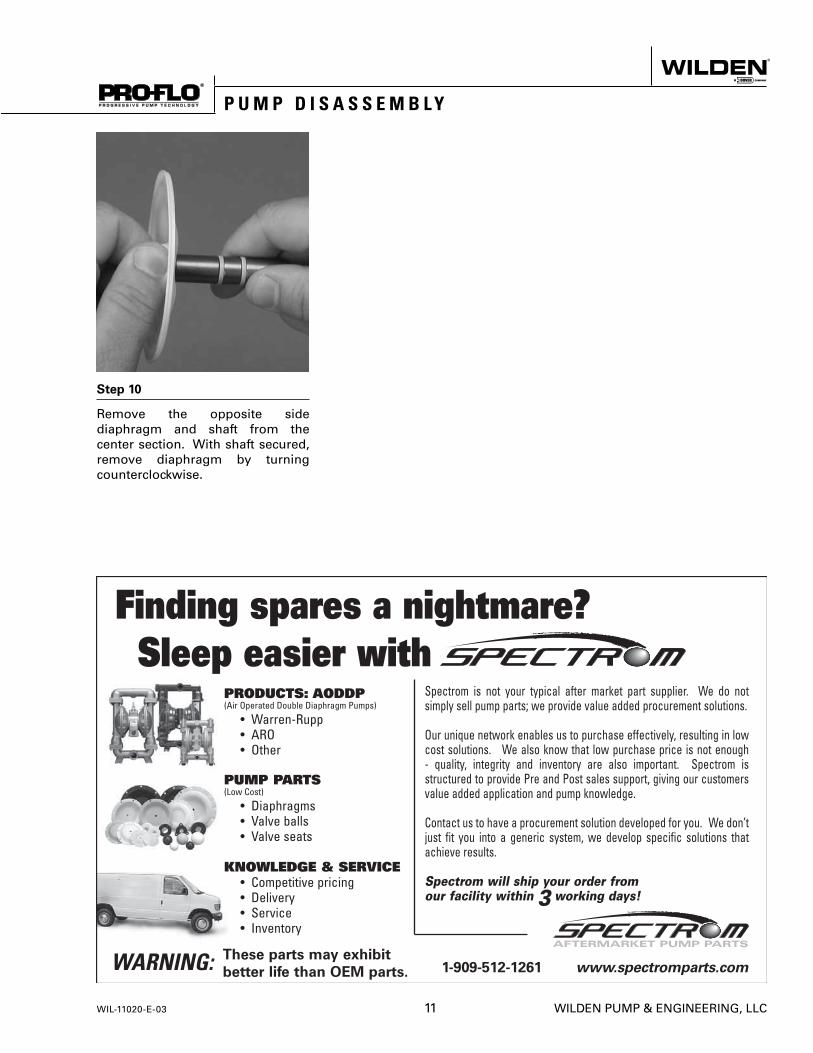
Step 10
Remove the opposite side diaphragm and shaft from the center section. With shaft secured, remove diaphragm by turning counterclockwise.
P U M P D I S A S S E M B L Y
WIL-11020-E-03 11 WILDEN PUMP & ENGINEERING, LLC

A I R V A L V E / C E N T E R S E C T I O N D I S A S S E M B L Y
To o l s R e q u i r e d :
• 5/32" Hex Head Wrench
• O-ring Pick
CAUTION: Before any maintenance or repair is attempted, the compressed air line to the pump should be disconnected and all air pressure allowed to bleed from the pump. Disconnect all intake, discharge, and air lines. Drain the pump by turning it upside down and allowing any fl uid to fl ow into a suitable container. Be aware of hazardous effects of contact with your process fl uid.
The Wilden P25 Advanced™ plastic utilizes a revolutionary Pro-Flo® air distribution system. Proprietary composite seals reduce the coeffi cient of friction and allow the P25 to run lube-free. Constructed of polypropylene, the Pro-Flo® air distribution system is designed to perform in on/off, non-freezing, non-stalling, tough duty applications.
Step 1
Remove air valve screws from center section with a 5/32" hex head wrench.
Step 2
Take care while removing air valve not to damage gasket.
NOTE: Air valve has molded-in alignment pins for proper positioning during assembly.
Step 3
Remove air valve end cap by simply pulling it away from air valve body (no tools required). Inspect o-ring and replace as needed with genuine Wilden parts.
WILDEN PUMP & ENGINEERING, LLC 12 WIL-11020-E-03

Step 4
The air valve spool can now be removed. A 10-24 UNC (Unifi ed National Coarse thread) screw can be screwed into the threaded hole located in the center of the spool. Grip the screw with pliers and remove. If a 10-24 UNC screw is not available, the spool can be tapped out against a wood block or blown out with compressed air. Upon reassembly, lubricate air valve with NLGI grade 2 white EP bearing grease.
Step 5
Remove the porous polyethylene muffl er element by sliding it toward the end cap opening. The element can be cleaned by soaking it in a cleaning solution (no solvents). If the muffl er restricts the air exhaust, replace muffl er element.
Step 6
Remove pilot spool retaining ring with an o-ring pick.
Step 7
Push pilot spool through center section and remove. Inspect seals for integrity and spool for damage. Replace pilot spool assembly if necessary. Upon reassembly of spool, apply a small amount of NLGI grade 2 white EP bearing grease or equivalent (P/N 99-8310-99).
A I R V A L V E / C E N T E R S E C T I O N D I S A S S E M B L Y
WIL-11020-E-03 13 WILDEN PUMP & ENGINEERING, LLC

MAXIMUM TORQUE SPECIFICATIONS
Description of Part Torque
Air Valve [2.3 N•m] 20 in.-lbs.
Liquid Chamber Bolt [6.2 N•m] 55 in.-lbs.
Manifold Bolt [6.2 N•m] 55 in.-lbs.
P U M P R E A S S E M B L Y
WILDEN PUMP & ENGINEERING, LLC 14 WIL-11020-E-03
Upon performing applicable maintenance to the air distribution system, the pump can now be reassembled. Please refer to the disassembly instructions for photos and parts placement. To reassemble pump, follow
the disassembly instructions in reverse order. The air distribution system needs to be assembled fi rst, then the diaphragms, and fi nally the wetted parts. Please fi nd applicable torque specifi cations in this section.
PTFE diaphragm confi guration
Lubricate the main shaft assembly with NLGI grade 2 white EP bearing grease or equivalent and insert through main shaft bore in center section. Assemble the other side and torque to proper value as listed below. Please review the photos above for proper alignment.

WIL-11020-E-03 15 WILDEN PUMP & ENGINEERING, LLC
9
3
2
5 8
6
1 4
17
1920212223
18
1112 13
14
15
107
16
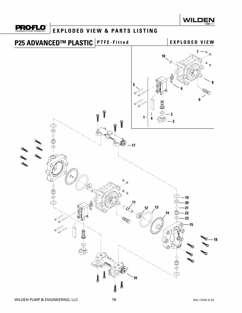
E X P L O D E D V I E W & P A R T S L I S T I N G
P25 ADVANCED™ PLASTIC P T F E - F i t t e d E X P L O D E D V I E W
WILDEN PUMP & ENGINEERING, LLC 16 WIL-11020-E-03
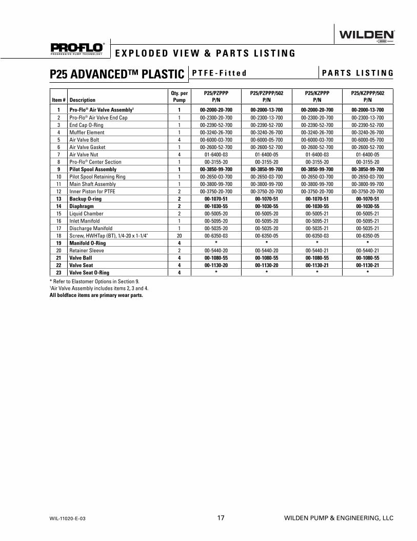
E X P L O D E D V I E W & P A R T S L I S T I N G
P25 ADVANCED™ PLASTIC P T F E - F i t t e d P A R T S L I S T I N G
Item # DescriptionQty. per Pump
P25/PZPPPP/N
P25/PZPPP/502P/N
P25/KZPPPP/N
P25/KZPPP/502P/N
1 Pro-Flo® Air Valve Assembly1 1 00-2000-20-700 00-2000-13-700 00-2000-20-700 00-2000-13-7002 Pro-Flo® Air Valve End Cap 1 00-2300-20-700 00-2300-13-700 00-2300-20-700 00-2300-13-7003 End Cap O-Ring 1 00-2390-52-700 00-2390-52-700 00-2390-52-700 00-2390-52-7004 Muffl er Element 1 00-3240-26-700 00-3240-26-700 00-3240-26-700 00-3240-26-7005 Air Valve Bolt 4 00-6000-03-700 00-6000-05-700 00-6000-03-700 00-6000-05-7006 Air Valve Gasket 1 00-2600-52-700 00-2600-52-700 00-2600-52-700 00-2600-52-7007 Air Valve Nut 4 01-6400-03 01-6400-05 01-6400-03 01-6400-058 Pro-Flo® Center Section 1 00-3155-20 00-3155-20 00-3155-20 00-3155-209 Pilot Spool Assembly 1 00-3850-99-700 00-3850-99-700 00-3850-99-700 00-3850-99-700
10 Pilot Spool Retaining Ring 1 00-2650-03-700 00-2650-03-700 00-2650-03-700 00-2650-03-70011 Main Shaft Assembly 1 00-3800-99-700 00-3800-99-700 00-3800-99-700 00-3800-99-70012 Inner Piston for PTFE 2 00-3750-20-700 00-3750-20-700 00-3750-20-700 00-3750-20-70013 Backup O-ring 2 00-1070-51 00-1070-51 00-1070-51 00-1070-5114 Diaphragm 2 00-1030-55 00-1030-55 00-1030-55 00-1030-5515 Liquid Chamber 2 00-5005-20 00-5005-20 00-5005-21 00-5005-2116 Inlet Manifold 1 00-5095-20 00-5095-20 00-5095-21 00-5095-2117 Discharge Manifold 1 00-5035-20 00-5035-20 00-5035-21 00-5035-2118 Screw, HWHTap (BT), 1/4-20 x 1-1/4" 20 00-6350-03 00-6350-05 00-6350-03 00-6350-0519 Manifold O-Ring 4 * * * *20 Retainer Sleeve 2 00-5440-20 00-5440-20 00-5440-21 00-5440-2121 Valve Ball 4 00-1080-55 00-1080-55 00-1080-55 00-1080-5522 Valve Seat 4 00-1130-20 00-1130-20 00-1130-21 00-1130-2123 Valve Seat O-Ring 4 * * * *
* Refer to Elastomer Options in Section 9. 1Air Valve Assembly includes items 2, 3 and 4.All boldface items are primary wear parts.
WIL-11020-E-03 17 WILDEN PUMP & ENGINEERING, LLC

S e c t i o n 9
E L A S T O M E R O P T I O N S
P25 ADVANCED™ PLASTIC
MATERIAL DIAPHRAGM BACK-UP O-RINGVALVE SEAT
O-RING MANIFOLD O-RINGNeoprene - 00-1070-51 - -PTFE 00-1030-55 - - -Viton® - 00-1070-53 - -EPDM - 00-1070-54 - -PTFE Encapsulated Viton® - - 00-1206-60 01-1200-60-520
WILDEN PUMP & ENGINEERING, LLC 18 WIL-11020-E-03

WIL-11020-E-03 19 WILDEN PUMP & ENGINEERING, LLC
Item # Serial #
Company Where Purchased
Company Name
Industry
Name Title
Street Address
City State Postal Code Country
Telephone Fax E-mail Web Address
Number of pumps in facility? Number of Wilden pumps?
Types of pumps in facility (check all that apply): Diaphragm Centrifugal Gear Submersible Lobe
Other
Media being pumped?
How did you hear of Wilden Pump? Trade Journal Trade Show Internet/E-mail Distributor
Other
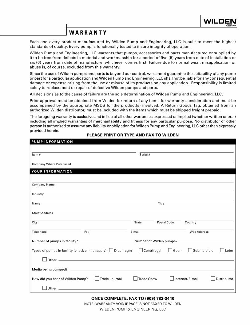
P U M P I N F O R M AT I O N
PLEASE PRINT OR TYPE AND FAX TO WILDEN
YO U R I N F O R M AT I O N
ONCE COMPLETE, FAX TO (909) 783-3440
NOTE: WARRANTY VOID IF PAGE IS NOT FAXED TO WILDEN
WILDEN PUMP & ENGINEERING, LLC
W A R R A N T YEach and every product manufactured by Wilden Pump and Engineering, LLC is built to meet the highest standards of quality. Every pump is functionally tested to insure integrity of operation.
Wilden Pump and Engineering, LLC warrants that pumps, accessories and parts manufactured or supplied by it to be free from defects in material and workmanship for a period of five (5) years from date of installation or six (6) years from date of manufacture, whichever comes first. Failure due to normal wear, misapplication, or abuse is, of course, excluded from this warranty.
Since the use of Wilden pumps and parts is beyond our control, we cannot guarantee the suitability of any pump or part for a particular application and Wilden Pump and Engineering, LLC shall not be liable for any consequential damage or expense arising from the use or misuse of its products on any application. Responsibility is limited solely to replacement or repair of defective Wilden pumps and parts.
All decisions as to the cause of failure are the sole determination of Wilden Pump and Engineering, LLC.
Prior approval must be obtained from Wilden for return of any items for warranty consideration and must be accompanied by the appropriate MSDS for the product(s) involved. A Return Goods Tag, obtained from an authorized Wilden distributor, must be included with the items which must be shipped freight prepaid.
The foregoing warranty is exclusive and in lieu of all other warranties expressed or implied (whether written or oral) including all implied warranties of merchantability and fitness for any particular purpose. No distributor or other person is authorized to assume any liability or obligation for Wilden Pump and Engineering, LLC other than expressly provided herein.