P1M Series Swing Clamp - SeekPartfile.seekpart.com/keywordpdf/2011/3/30/2011330105215208.pdf · 3...
16
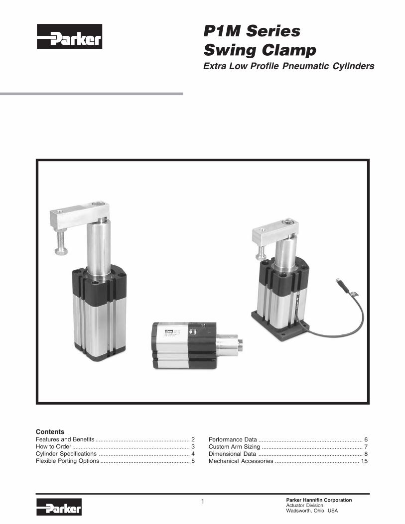
1 Parker Hannifin Corporation Actuator Division Wadsworth, Ohio USA P1M Series Swing Clamp Extra Low Profile Pneumatic Cylinders zc03 Contents Features and Benefits ......................................................... 2 How to Order ....................................................................... 3 Cylinder Specifications ....................................................... 4 Flexible Porting Options ...................................................... 5 Performance Data ............................................................... 6 Custom Arm Sizing ............................................................. 7 Dimensional Data ............................................................... 8 Mechanical Accessories ................................................... 15
Transcript of P1M Series Swing Clamp - SeekPartfile.seekpart.com/keywordpdf/2011/3/30/2011330105215208.pdf · 3...
1 Parker Hannifin CorporationActuator DivisionWadsworth, Ohio USA
P1M SeriesSwing ClampExtra Low Profile Pneumatic Cylinders zc03
ContentsFeatures and Benefits ......................................................... 2How to Order ....................................................................... 3Cylinder Specifications ....................................................... 4Flexible Porting Options ...................................................... 5
Performance Data ............................................................... 6Custom Arm Sizing ............................................................. 7Dimensional Data ............................................................... 8Mechanical Accessories ................................................... 15

Swing Clamp CylindersP1M Series
Parker Hannifin CorporationActuator DivisionWadsworth, Ohio USA
2
C086
Parker is pleased to announce the addition of theP1M Swing Clamp Cylinder to the P1M Series productline. The P1M Swing Clamp Cylinder incorporatesseveral innovative features including: 3-piece boltedconstruction, internal transfer tube, long bearing headoption standard, bumpers standard, outboard rotating
guide mechanism, and recessed sensor grooves.The combination of these features, in addition tomaintaining the smallest dimensional envelopepossible, make the P1M Swing Clamp Cylinder idealfor applications that require a compact design andsuperior clamping capability.
Catalog AU03-0900P-2/NA
Features and Benefits

3 Parker Hannifin CorporationActuator DivisionWadsworth, Ohio USA
Swing Clamp CylindersP1M Series
C086
How to Order P1M Series Swing Clamp Cylinders
* Cylinder with mounting fitted** Designator # 3 should be selected for special rod ends only. When selecting this option, please provide
rod style (male or female), thread pitch, thread depth, and wrench flat dimension.*** Both Ports Head NPT is the standard porting arrangement for this cylinder. Alternate porting
arrangements are available at an additional cost.+ Bumpers for this option are polyurethane. Piston, rod and body end seals are fluorocarbon.
Please review the following specification page for additional information.! Designator J should be selected for cylinders that require a special option not covered in catalog.!! See specification table for stroke lengths available per a given bore size.
Note: For sensor specifications and part numbers, please refer to the electronic sensors section.
PneumaticActuators
P 1 M 0 3 2 C H F M C 6 M 0 2 0
Series
Bore Size
CylinderStyle
C Basic, no mountingH Rear Flange*K Clamp Arm*
L Rear Flange &Clamp Arm*
CylinderOption
H Swing Clamp
J Swing Clamp Special(MTO) !
Function
F Right Hand RotationL Left Hand Rotation
Strokein mm !!
Port Type& Location
BSPP “G” ThreadsG Head & Cap RadialH Both in HeadJ Both in Cap RadialK Both in Cap Axial
NPT ThreadsN Head & Cap RadialM Both in Head***L Both in Cap RadialP Both in Cap Axial
BSPT “R” ThreadsQ Head & Cap RadialR Both in HeadS Both in Cap RadialT Both in Cap Axial
6 Metric Female3 Special**
RodThreads
Piston Rod& Bearings
C Chrome PlatedCarbon SteelB No Magnet, Bumpers,
Standard Seals
F No Magnet, Bumpers,Fluorocarbon Seals +
M Magnetic Piston,Bumpers, Std. SealsMagnetic Piston,
V Bumpers,Fluorocarbon Seals +
Bumpers,Magnet& Seals
032 32mm040 40mm050 50mm
Catalog AU03-0900P-2/NA
How to Order
Bore Class 132 L07866003240 L07866004050 L078660050
Seal Kit Part NumbersClass 5
L078670032L078670040L078670050
Service kits of expendable parts for fluid power cylinders arestocked in principal industrial locations across the U.S.A.and other countries. For prompt delivery and completeinformation, contact your nearest distributor.

Swing Clamp CylindersP1M Series
Parker Hannifin CorporationActuator DivisionWadsworth, Ohio USA
4
C086
Catalog AU03-0900P-2/NA
Cylinder Specifications
Cylinder Specifications• Bore Sizes: 32, 40 and 50mm• Maximum Operating Pressure: 10 Bar or 145 PSI• Standard Operating Temperature: -20°C to +80°C or -4°F to +176°F• Optional High Temperature: -10°C to +121°C or +14°F to +250°F
Material Specifications• Piston Rod: Hard Chrome Plated Steel, 100,000 PSI Yield• Piston Rod Bearing: Multilayer PTFE with Steel Backing• Outboard Rotating Mechanism Cover: 2011 T3 Aluminum• End Covers: Black Anodized Aluminum• End Cover Fasteners: Zinc Plated Carbon Steel• Cylinder Body: Clear Anodized Aluminum• O-Rings: Nitrile Rubber, NBR• Piston: Aluminum Alloy• Piston Seal: Nitrile Rubber, NBR• Magnet: Plastic Coated Magnetic Material• Bumpers: Polyurethane
High Temperature Seal Option Material*• End Cover O-Rings: Fluorocarbon, FPM• Piston Rod Seal: Fluorocarbon, FPM• Piston Seal: Fluorocarbon, FPM
*Option intended for limited exposure to temperatures over 80°C, or 176°F. Option isprimarily for applications which subject the cylinder to fluids and or chemicals that have anadverse effect on external seals. If continued exposure to elevated temperatures isrequired, please consult the Cylinder Division for alternative options.
Cylinder Weights, g (lbs)Bore, Clamp Stroke,mm mm
10 600 (1.32) 691 (1.52) 664 (1.46) 755 (1.66)
20 673 (1.48) 764 (1.68) 736 (1.62) 827 (1.82)
10 700 (1.54) 791 (1.74) 782 (1.72) 873 (1.92)
20 800 (1.76) 891 (1.96) 882 (1.94) 973 (2.14)
20 1355 (2.98) 1527 (3.36) 1500 (3.30) 1673 (3.68)
50 1736 (3.82) 1909 (4.20) 1882 (4.14) 2055 (4.52)
Arm & FlangeMount
32
40
Rear FlangeMount
50
BasicMount
Clamp ArmMount
Clamp Forces, N (lbs)Bore, Rod Dia, Net Area,mm mm cm2 0.2 (29) 0.4 (58) 0.6 (87) 0.8 (116) 1.0 (145)
32 16 6.03 121 (27) 241 (54) 362 (81) 483 (108) 603 (136)
40 16 10.56 211 (47) 422 (95) 633 (142) 844 (190) 1056 (237)
50 20 16.49 330 (74) 660 (148) 990 (222) 1319 (297) 1649 (371)
Operating Pressure, MPa (psi)
Specifications32 40 50
Rotary Stroke, mm 19
Clamp Stroke, mm 20 / 50Allowable Moment, N-m (ft-lbs) 27 (20) 47 (35) 107 (79)
Degree of Non-Rotation +/- 1.0o +/- 1.0o +/- 0.8o
15
10 / 20
Bore, mmSpecifications

5 Parker Hannifin CorporationActuator DivisionWadsworth, Ohio USA
Swing Clamp CylindersP1M Series
C086
Catalog AU03-0900P-2/NA
Flexible Porting Options
P1M Series Swing Clamp Flexible Porting Options
Both Ports Head* Both Ports Cap
Head and Cap PortedBoth Ports Cap Face
2
4
2
4
42
2
4
To retract cylinder, apply air to port #2.To extend cylinder, apply air to port #4.
* Both Ports Head (NPT) is the standard porting configuration for theP1M Swing Clamp Cylinder. Alternate porting options are available atan additional cost.
Right Hand (Clockwise)Clamping Rotation
Left Hand (Counter-Clockwise)Clamping Rotation

Swing Clamp CylindersP1M Series
Parker Hannifin CorporationActuator DivisionWadsworth, Ohio USA
6
C086
Catalog AU03-0900P-2/NA
Performance Data
The following graph represents maximum clamp arm lengths per a given bore and operatingpressure. Care should be taken not to exceed maximum operating limits outlined in this graph.
Guidelines for Custom Clamp Arms
0
25
50
75
100
125
150
175
200
225
250
0.1 0.2 0.3 0.4 0.5 0.6 0.7 0.8 0.9 1.0
Arm
Len
gth
(m
m)
32mm & 40mm Bores
50mm Bore
Pressure (MPa)
0.000
0.005
0.010
0.015
0.020
0.025
0.030
20 40 60 80 100 120 140 160 180 200
32mm & 40mm Bores
50mm Bore
Cylinder Speed (mm/s)
Mo
men
t o
f In
erti
a (k
g-m
2 )
The following graph represents maximum operating speeds per a given inertia moment whenincorporating a custom clamp arm. Exceeding the parameters outlined in the graph will lead tointernal cylinder component damage. Please refer to the following page for examples andformulas when designing the clamp arm to be applied.

7 Parker Hannifin CorporationActuator DivisionWadsworth, Ohio USA
Swing Clamp CylindersP1M Series
C086
Catalog AU03-0900P-2/NA
Custom Arm Sizing
Please use the following formulas and sizing examples when determiningwhat style of clamp arm will best suit your application requirements.
1) Round Bar (Asymmetric)Clamping arm is positioned 90° degrees to thepiston rod assembly, and is fixed at or near theend of the arm.
2) Round Bar (Symmetric)Clamping arm is positioned 90° degrees to thepiston rod assembly, and is fixed at the centerof the arm.
3) Rectangular Bar (Asymmetric)Clamping arm is positioned 90° degrees to thepiston rod assembly, and is fixed at or near theend of the arm.
4) Rectangular Bar (Symmetric)Clamping arm is positioned 90° degrees to thepiston rod assembly, and is fixed at the centerof the arm.
5) Rectangular Bar with BoltClamping arm is positioned 90° degrees to thepiston rod assembly, and is fixed at or near theend of the arm.
6) Round Bar with SphereClamping arm is positioned 90° degrees to thepiston rod assembly, and is fixed at or near theend of the arm.
ØDL
+=
163
22 DLmI
+=
1612
22 DLmI
L
ØD
L
W
+=
123
22 WLmI
L
W
+=12
22 WLmI
W
L2L1
ØD
L1
L2R
M2M1
ØD
++
+= 2
2
2
2
221
1 5
2
163L
rm
DLmI
++
+=
123163
222
2
221
1
WLm
DLmI

Swing Clamp CylindersP1M Series
Parker Hannifin CorporationActuator DivisionWadsworth, Ohio USA
8
C086
Catalog AU03-0900P-2/NA
Dimensions – Head Ported
Head Ported Dimensions
*Both Ports Head (NPT) is the standard porting configuration for the P1M Swing Clamp Cylinder.Alternate porting options are available at an additional cost.
BSPP NPTF
32 18 46.5 17 48 56 24 G 1/8 1/8 1.1 9 5.5 13.5 4 M10x1.5
40 18 39 17.5 56 62.5 28 G 1/8 1/8 1.5 9 5.5 10 4 M10x1.5
50 25 47.5 23.5 67 74.5 33.5 G 1/8 1/8 2 12 5.5 12 5 M12x1.75
-0.1-0.2 I79 ZH9 I78 ZH8
32 25 16 9.5 30.5 34 10.5 M6x1 3 6.5 30 h9 67 92.5 76 101.5
40 20 16 11.5 22 40 10.5 M6x1 3 6.5 30 h9 60 92.5 70 102.5
50 20 20 14.5 28 50 13.5 M8x1.25 3.5 7.5 37 h9 72.5 113 81.5 122
14
L Y
BG1 E E1 E2BG2
SWRT
I12
MM NB PM R R1
Rc 1/8
Rc 1/8
EE1AFBSPT
Rc 1/8
Bore
BoreEE
I91
14
17
MagneticNon-MagneticVD WH
I92 KFHL
R
E2
E1
ØMM
R
E
L˚ L˚
NB NB
SW
ØY
I12
WH
VD
PM
I79 (I78) + CLAMP STROKE
ZH9 (ZH8) + 2X CLAMP STROKE
KF AF
I91
BG1BG2
I92
RT HLØR1 I91
MTG. HOLES @180˚2 PLACES EACH SIDE
HLHL
ØR1
ØR1
MOUNTING HOLE CONFIGURATION(2 PLACES)
2X ØEE PORT, ØEE1 ORIFICE

9 Parker Hannifin CorporationActuator DivisionWadsworth, Ohio USA
Swing Clamp CylindersP1M Series
C086
Catalog AU03-0900P-2/NA
Dimensions – Head and Cap Ported
Head and Cap Ported Dimensions
BSPP BSPT
32 18 46.5 25 48 56 24 G 1/8 Rc 1/8 1.1 2.7 9 5.5 13.5 11.5 M10x1.5
40 18 39 25.5 56 62.5 28 G 1/8 Rc 1/8 1.5 3.4 9 5.5 10 12 M10x1.5
50 25 47.5 29.5 67 74.5 33.5 G 1/8 Rc 1/8 2 4 12 5.5 12 11 M12x1.75
-0.1-0.2 I79 ZH9 I78 ZH8
32 25 16 9.5 8 30.5 34 10.5 M6x1 3 6.5 30 h9 75 100.5 84 109.5
40 20 16 11.5 7.5 22 40 10.5 M6x1 3 6.5 30 h9 68 100.5 78 110.5
50 20 20 14.5 8 28 50 13.5 M8x1.25 3.5 7.5 37 h9 78.5 119 87.5 128
I91
17
MagneticNon-MagneticVD WH
I92 KFEE1 HLEE2
14
I12
R R1 SWRT
1/8
14
Bore
Bore AF
Y
BG1 E1 E2BG2EE
NPTF
L
E
1/8
1/8
PMMM NB PL
E2
E1
ØMM
R
E
R
NB NB
L˚ L˚
SW
I12
VD
I79 (I78) + CLAMP STROKE
ZH9 (ZH8) + 2X CLAMP STROKE
WH ØY
PM PL
KF AF
ØEE PORTØEE1 ORIFICE
ØEE PORTØEE2 ORIFICE
I91
BG1
ØR1
I92
BG2
ØR1HL
HL
MOUNTING HOLE CONFIGURATION(2 PLACES)
RT HLØR1 I91
MTG. HOLES @180˚2 PLACES EACH SIDE

Swing Clamp CylindersP1M Series
Parker Hannifin CorporationActuator DivisionWadsworth, Ohio USA
10
C086
Catalog AU03-0900P-2/NA
Dimensions – Cap Ported Radial
Cap Radial Ported Dimensions
BSPP NPTF
32 18 46.5 25 48 56 24 G 1/8 1/8 1.1 9 5.5 13.5 11.5 M10x1.5
40 18 39 25.5 56 62.5 28 G 1/8 1/8 1.5 9 5.5 10 12 M10x1.5
50 25 47.5 29.5 67 74.5 33.5 G 1/8 1/8 2 12 5.5 12 11 M12x1.75
-0.1-0.2 I79 ZH9 I78 ZH8
32 25 16 9.5 8 34 10.5 M6x1 3 6.5 30 h9 75 100.5 84 109.5
40 20 16 11.5 7.5 40 10.5 M6x1 3 6.5 30 h9 68 100.5 78 110.5
50 20 20 14.5 8 50 13.5 M8x1.25 3.5 7.5 37 h9 78.5 119 87.5 128
I91
14
L Y
BG1 E E1 E2BG2BSPT
I12
MM NB PL R
Rc 1/8
SWRTR1
Rc 1/8
AFEE
Bore
Bore
Rc 1/8
I92 KF
14
17
MagneticNon-MagneticVD WH
EE1 HL
R
ØMM
R
E
NB NB
L˚ L˚
E2
E1
SW
I12
VD
I79 (I78) + CLAMP STROKE
ZH9 (ZH8) + 2X CLAMP STROKE
KF AF
WH ØY
PLØEE PORTØEE1 ORIFICE
I91
BG1
ØR1
I92
BG2
ØR1HL
HL
MOUNTING HOLE CONFIGURATION(2 PLACES)
RT HLØR1 I91
MTG. HOLES @180˚2 PLACES EACH SIDE

11 Parker Hannifin CorporationActuator DivisionWadsworth, Ohio USA
Swing Clamp CylindersP1M Series
C086
Catalog AU03-0900P-2/NA
Dimensions – Cap Rear Face Porting
Cap Rear Face Ported Dimensions
BSPP BSPT
32 18 46.5 25 48 56 24 G 1/8 Rc 1/8 1.1 9 5.5 13.5 11.5 M10x1.5
40 18 39 25.5 56 62.5 28 G 1/8 Rc 1/8 1.5 9 5.5 10 12 M10x1.5
50 25 47.5 29.5 67 74.5 33.5 G 1/8 Rc 1/8 2 12 5.5 12 11 M12x1.75
-0.1-0.2 I79 ZH9 I78 ZH8
32 16 45.5 16.5 32 28.5 34 10.5 M6x1 3 6.5 30 h9 75 100.5 84 109.5
40 16 51 12 23 33 40 10.5 M6x1 3 6.5 30 h9 68 100.5 78 110.5
50 20 63 54.5 25 41.5 50 13.5 M8x1.25 3.5 7.5 37 h9 78.5 119 87.5 128
I92 KF
17
MagneticNon-MagneticVD WHSW
14
YBore
Bore I91
14
EE1 HL I12
MM P1 P4 R
AF
P2 P3
BG1 E E1 E2BG2EE
NPTF
1/8
RTR1
1/8
1/8
R
E2
E1
SW
P2
P3
P4
P1
ØMM
R
E
I12VD
I79 (I78) + CLAMP STROKE
ZH9 (ZH8) + 2X CLAMP STROKE
WH
ØY
2X ØEE PORT,ØEE1 ORIFICE
I91
BG1 I92
BG2
ØR1
HLHLØR1
MOUNTING HOLE CONFIGURATION(2 PLACES)
KF AF
RT HLØR1 I91
MTG. HOLES @180˚2 PLACES EACH SIDE
Swing Clamp CylindersP1M Series
Parker Hannifin CorporationActuator DivisionWadsworth, Ohio USA
12
C086
Catalog AU03-0900P-2/NA
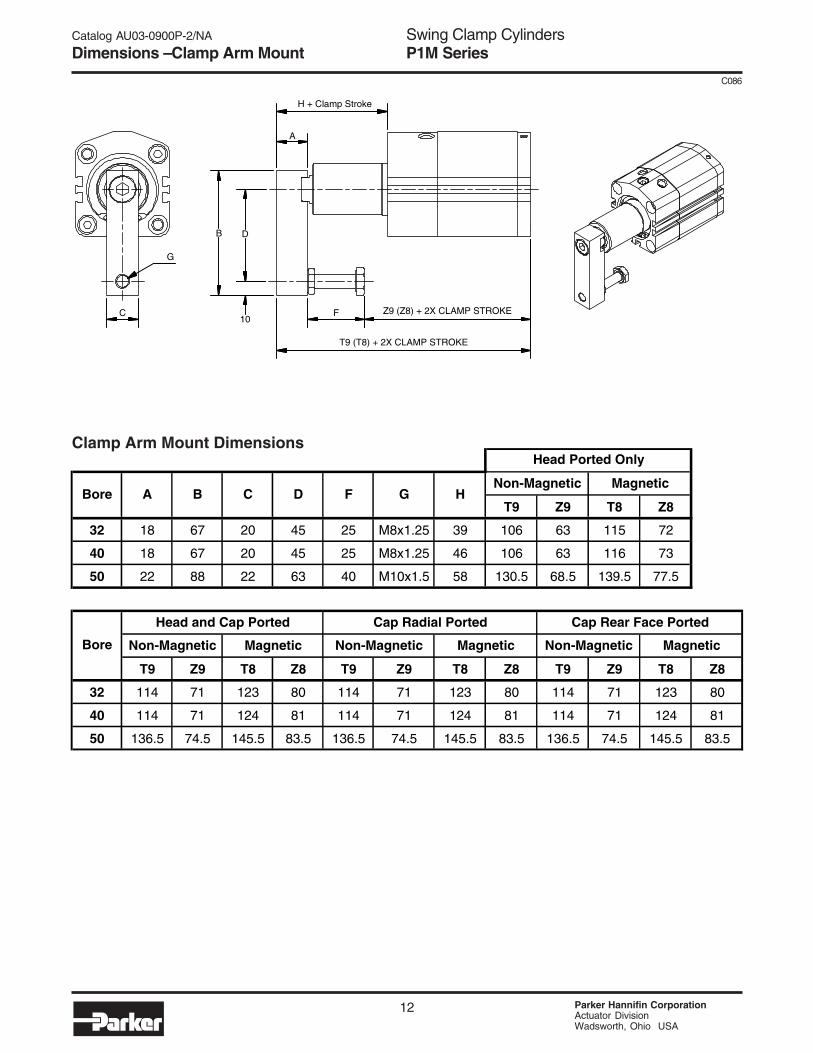
Dimensions – Clamp Arm Mount
C
D
10
B
F
G
A
H + Clamp Stroke
T9 (T8) + 2X CLAMP STROKE
Z9 (Z8) + 2X CLAMP STROKE
Clamp Arm Mount Dimensions
T9 Z9 T8 Z8
32 18 67 20 45 25 M8x1.25 39 106 63 115 72
40 18 67 20 45 25 M8x1.25 46 106 63 116 73
50 22 88 22 63 40 M10x1.5 58 130.5 68.5 139.5 77.5
T9 Z9 T8 Z8 T9 Z9 T8 Z8 T9 Z9 T8 Z8
32 114 71 123 80 114 71 123 80 114 71 123 80
40 114 71 124 81 114 71 124 81 114 71 124 81
50 136.5 74.5 145.5 83.5 136.5 74.5 145.5 83.5 136.5 74.5 145.5 83.5
Non-Magnetic Magnetic
Head Ported Only
Cap Rear Face Ported
Non-Magnetic MagneticBore
Head and Cap Ported
Non-Magnetic Magnetic
Cap Radial Ported
Non-Magnetic Magnetic
Bore CA B D F G H

13 Parker Hannifin CorporationActuator DivisionWadsworth, Ohio USA
Swing Clamp CylindersP1M Series
C086
Catalog AU03-0900P-2/NA
Dimensions – Rear Flange Mount
RE
R
TF
UF
MF
4X ØFB
ZF2 (ZF3) + 2X CLAMP STROKE
Rear Flange Mount Dimensions
Bore E
ZF2
Head Ported Only
79
FB MF R
32
ZF3 ZF2
Bore
5.5
Head and Cap Ported
ZF3
Non-Magnetic
67 6.6
Cap Radial Ported
40
50
8 40 66 76
9
108.5
TF UF
48
54
5.5 8 34 58 68
128
90
32
40
117.5
Magnetic Non-Magnetic Magnetic
50
Rear Flange Mounting Kits can be ordered assembled to the cylinder or separately as needed. Please refer to Page #?? for proper rear flange mounting kits associated with a given bore size.
118.5
50
100.5 109.5 108.5
100.5 110.5 108.5
122 131
Non-Magnetic
137 128 137
Magnetic
108.5
118.5
ZF2 ZF3
117.5
Rear Flange Mounting Kits can beordered assembled to the cylinder orseparately as needed. Please referto page 15 for proper rear flangemounting kits associated with a givenbore size.

Swing Clamp CylindersP1M Series
Parker Hannifin CorporationActuator DivisionWadsworth, Ohio USA
14
C086
Catalog AU03-0900P-2/NA
Dimensions – Rear Flange/Clamp Arm Mount
Rear Flange and Clamp Arm Mount Dimensions
C
G
DB
10
A
H + CLAMP STROKE
F Z2 (Z3) + 2X CLAMP STROKE
T2 (T3) + 2X CLAMP STROKE
MF
RE
4X ØFB
R
TF
UF
154.5 92.5
6.5 9
122
122
58
45 48
5.5
80
54
63 67
Z3
25
40
40 18 67 4520
M10x1.5
58
40 66
FB MF R
85.520
C UF
39
H TFD E F
34
Bore A B
8
G
M8x1.25
M8x1.25
32 18 67
76
50 22 88 22 50 79 90
4625
68
Bore Non-Magnetic Magnetic Non-Magnetic
T2 Z2 T3 T2 Z2
Magnetic
Head Ported Only Head and Cap Ported Cap Radial Ported
Magnetic Non-Magnetic
Z3
114 71 123 122 79 131 88
T3 Z3 Z2 T3T2
83.5 154.5145.5
88
114 71 124 122 79 132 8981
77.5 148.5 145.5 83.586.5 92.5
32
40
50
79 132 89
139.5
79 131
SPANNER WRENCHPART # 0116760000
GLAND WRENCHPART # 0883060000
32mm Bore Assembly
To disassemble the front end cover, therod cover must first be removed. To dothis the ring nut must be unscrewed(right-hand thread) using the spannerand gland wrench shown to the left.Order each component separately.

15 Parker Hannifin CorporationActuator DivisionWadsworth, Ohio USA
Swing Clamp CylindersP1M Series
C086
Catalog AU03-0900P-2/NA
Mechanical Accessories
Clamp Arm Mounting Kit 32, 40, and 50mm Bore
Clamp Arm Mounting Kit Component Identification
Rear Flange Mount Kit 32, 40, and 50mm Bore
Rear Flange Mounting Kit Component Identification
1
5
4
2
3
Bore, Partmm Number N-m Inch-lbs32 L078550000 8 - 10 70 - 88
40 L078550000 8 - 10 70 - 88
50 L078560000 14 - 16 124 - 142
Fastener Torque Item PartNumber Description Material
1 Clamp Arm Aluminum
2 Clamp Bolt Steel
3 Hex Jam Nut Steel
4 Socket Head Cap Screw Steel
5 Lock Washer Steel
Note: To remove or install the arm on the piston rod, use a wrench to secure the arm while looseningor tightening the socket head cap screw. Do not secure any other part of the cylinder.
1
2
2
Bore, Partmm Number N-m Inch-lbs32 P1M-4KMB 3.6 - 4.0 32 - 36
40 P1M-4LMB 3.6 - 4.0 32 - 36
50 P1M-4MMB 8.0 - 9.0 72 - 80
Fastener Torque Item PartNumber Description Material
1 Flange Aluminum
2 Socket Head Cap Screw Steel

Swing Clamp CylindersP1M Series
Parker Hannifin CorporationActuator DivisionWadsworth, Ohio USA
16
C086
Catalog AU03-0900P-2/NA
Notes
NOTES