P14x RNC1 TM en 1 Release Notes
18
MiCOM P14x © ALSTOM 2013. All rights reserved. Information contained in this document is indicative only. No representation or warranty is given or should be relied on that i t is complete or correct or will apply to any particular project. This will depend on the technical and commercial circumstances. It is provided without liability and is subject to change without notice. Reproduction, use or disclosure to third parties, without express written authority, is strictly prohibited. Release Notes P14x Upgrade Platform Hardware Version: J Platform Software Version: 50 Publication Reference: P14x-RNC1-TM-EN-1
-
Upload
vijayaganthaan-visvanatthan -
Category
Documents
-
view
234 -
download
0
Transcript of P14x RNC1 TM en 1 Release Notes

8/11/2019 P14x RNC1 TM en 1 Release Notes
http://slidepdf.com/reader/full/p14x-rnc1-tm-en-1-release-notes 1/18
MiCOM P14x
© ALSTOM 2013. All rights reserved. Information contained in this document is indicative only. No representation or warranty is
given or should be relied on that i t is complete or correct or will apply to any particular project. This will depend on the technical
and commercial circumstances. It is provided without liability and is subject to change without notice. Reproduction, use or
disclosure to third parties, without express written authority, is strictly prohibited.
Release Notes
P14x Upgrade
Platform Hardware Version: J
Platform Software Version: 50
Publication Reference: P14x-RNC1-TM-EN-1

8/11/2019 P14x RNC1 TM en 1 Release Notes
http://slidepdf.com/reader/full/p14x-rnc1-tm-en-1-release-notes 2/18
8/11/2019 P14x RNC1 TM en 1 Release Notes
http://slidepdf.com/reader/full/p14x-rnc1-tm-en-1-release-notes 3/18
Contents
Supplement
1
P14x Release Notes 1
1 Introduction 3
2 Second Harmonic Blocking Using SEF Input 4
2.1 Second Harmonic Blocking Using SEF Protection DDBs 4
2.2 Second Harmonic Blocking Using SEF Input Settings 4
2.3 Second Harmonic Blocking Using SEF Input Logic 4
3 Display Check Sync Difference Voltage 6
4 Hot-Standby Ethernet Failover 7
4.1 Hot-Standby Ethernet Failover Settings 7
5 Loss of SNTP Server Signal Alarm 8
6 Circuit Breaker Fail Logic 9
7 CB Fail DDB signals 12

8/11/2019 P14x RNC1 TM en 1 Release Notes
http://slidepdf.com/reader/full/p14x-rnc1-tm-en-1-release-notes 4/18
Contents P14x
ii P14x-RNC1-TM-EN-1
8/11/2019 P14x RNC1 TM en 1 Release Notes
http://slidepdf.com/reader/full/p14x-rnc1-tm-en-1-release-notes 5/18
P14X RELEASE NOTES
SUPPLEMENT 1

8/11/2019 P14x RNC1 TM en 1 Release Notes
http://slidepdf.com/reader/full/p14x-rnc1-tm-en-1-release-notes 6/18
Supplement 1 - P14x Release Notes P14x
2 P14x-RNC1-TM-EN-1
8/11/2019 P14x RNC1 TM en 1 Release Notes
http://slidepdf.com/reader/full/p14x-rnc1-tm-en-1-release-notes 7/18
1 INTRODUCTION
These release notes apply to the following products:
● P141● P142
● P143
● P144
● P145
P14x Supplement 1 - P14x Release Notes
P14x-RNC1-TM-EN-1 3

8/11/2019 P14x RNC1 TM en 1 Release Notes
http://slidepdf.com/reader/full/p14x-rnc1-tm-en-1-release-notes 8/18

8/11/2019 P14x RNC1 TM en 1 Release Notes
http://slidepdf.com/reader/full/p14x-rnc1-tm-en-1-release-notes 9/18
Signal Name DDB #
ISEF>3 Timer Blk 218
ISEF 2H Start 762
IA2H Start 538
IB2H Start 539
IC2H Start 540
P14x Supplement 1 - P14x Release Notes
P14x-RNC1-TM-EN-1 5

8/11/2019 P14x RNC1 TM en 1 Release Notes
http://slidepdf.com/reader/full/p14x-rnc1-tm-en-1-release-notes 10/18
3 DISPLAY CHECK SYNC DIFFERENCE VOLTAGE
This function monitors the difference between the bus and line values of frequency, angle and voltage
magnitude. The CB is usually closed automatically. If it is closed manually, you need these measurements to
be able to decide when to close it.
This function supports Courier, CS103 Generic Services, DNP3 and IEC 61850 protocols. The IEC 61850
Logical Node Asc RSYN is used to display the measurement.
The C/S Bus-Line Mag cell is visible if System Checks is set to Enabled .
Supplement 1 - P14x Release Notes P14x
6 P14x-RNC1-TM-EN-1
8/11/2019 P14x RNC1 TM en 1 Release Notes
http://slidepdf.com/reader/full/p14x-rnc1-tm-en-1-release-notes 11/18
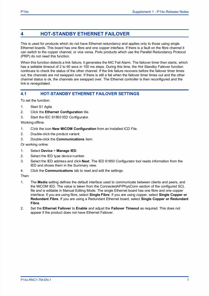
4 HOT-STANDBY ETHERNET FAILOVER
This is used for products which do not have Ethernet redundancy and applies only to those using single
Ethernet boards. This board has one fibre and one copper interface. If there is a fault on the fibre channel it
can switch to the copper channel, or vice versa. Px4x products which use the Parallel Redundancy Protocol(PRP) do not need this function.
When this function detects a link failure, it generates the NIC Fail Alarm. The failover timer then starts, which
has a settable timeout of 2 to 60 secs in 100 ms steps. During this time, the Hot Standby Failover function
continues to check the status of the other channel. If the link failure recovers before the failover timer times
out, the channels are not swapped over. If there is still a fail when the failover timer times out and the other
channel status is ok, the channels are swapped over. The Ethernet controller is then reconfigured and the
link is renegotiated.
4.1 HOT-STANDBY ETHERNET FAILOVER SETTINGS
To set the function:
1. Start S1 Agile.
2. Click the Ethernet Configuration tile.
3. Start the IEC 61850 IED Configurator.
Working offline:
1. Click the icon New MiCOM Configuration from an Installed ICD File.
2. Double-click the product variant.
3. Double-click the Communications item.
Or working online:
1. Select Device > Manage IED.
2. Select the IED type device number.
3. Select the IED address and click Next. The IED 61850 Configurator tool reads information from the
IED and shows them in the Summary view.
4. Click the Communications tab to read and edit the settings.
Then:
1. The Media setting defines the default interface used to communicate between clients and peers, and
the MiCOM IED. The value is taken from the ConnectedAP/PhysConn section of the configured SCL
file and is editable in Manual Editing Mode. The single Ethernet board has one fibre and one copper
interface. If you are using fibre, select Single Fibre. If you are using copper, select Single Copper or
Redundant Fibre. If you are using a Redundant Ethernet board, select Single Copper or Redundant
Fibre.
2. Set the Ethernet Failover to Enable and adjust the Failover Timeout as required. This does notappear if the product does not have Ethernet Failover.
P14x Supplement 1 - P14x Release Notes
P14x-RNC1-TM-EN-1 7

8/11/2019 P14x RNC1 TM en 1 Release Notes
http://slidepdf.com/reader/full/p14x-rnc1-tm-en-1-release-notes 12/18
5 LOSS OF SNTP SERVER SIGNAL ALARM
This function issues an alarm when there is a loss of time synchronization on the SNTP server. It is issued
when the SNTP sever has not detected a valid time synchronisation response within its 5 second window.
This is because there is no response or no valid clock. The alarm is mapped to IEC 61850.
Supplement 1 - P14x Release Notes P14x
8 P14x-RNC1-TM-EN-1
8/11/2019 P14x RNC1 TM en 1 Release Notes
http://slidepdf.com/reader/full/p14x-rnc1-tm-en-1-release-notes 13/18
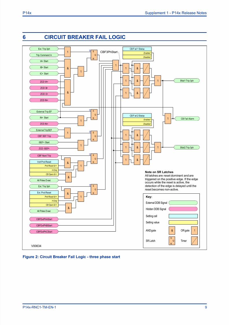
6 CIRCUIT BREAKER FAIL LOGIC
V00634
Ext. Trip 3ph
Trip Command In
1 S
R
Q
IA< Start
&IB< Start
IC< Start
External Trip EF
IN< Start
1
S
R
Q
External TripSEF
CBF SEF Trip
1 S
R
Q
ISEF< Start
CBF NonI Trip S
R
Q
Volt Prot Reset
I<Only CB Open & I<
Prot Reset & I<
&1
& All Poles D ead
Ext. Trip 3ph S
R
Q
Ext. Prot Reset
I<Only
CB Open & I<
Prot Reset & I<
&1
& All Poles D ead
Key:
External DDB Signal
& AND gate OR gate 1
Setting cell
Setting value
CB F ail 1 Status
&
1
1
1
1
1
1
&
&
&
&
&
CB F ail 2 Status
Bfail1 Trip 3ph
Bfail2 Trip 3ph
1
1
1
CB Fail Alarm
Hidden DDB Signal
Enabled
Disabled
Enabled
Disabled
S
R
QSR Latch Timer
CBFExtPhAStart
CBFExtPhBStart
CBFExtPhCStart
1
ZCD IA<
ZCD C<
ZCD B<
ZCD IN<
&
1ZCD IN<
ZCD ISEF<
1
Note on SR Latches
All latches are reset dominant and are
triggered on the positive edge. If the edgeoccurs while the reset is active, the
detection of the edge is delayed until the
reset becomes non-active.
CBF3PhStart
Figure 2: Circuit Breaker Fail Logic - three phase start
P14x Supplement 1 - P14x Release Notes
P14x-RNC1-TM-EN-1 9

8/11/2019 P14x RNC1 TM en 1 Release Notes
http://slidepdf.com/reader/full/p14x-rnc1-tm-en-1-release-notes 14/18
V00657
1
External Trip A
IA< Start
S
RQ
Key:
External DDB Signal
& AND gate OR gate 1
Setting cell
Setting value
S
R
Q
Ext. Prot Reset
I<Only
CB Open& I<
Prot Reset& I<
&1
&Pole Dead A
External Trip A
1
External Trip B
IB< Start
S
RQ
S
R
Q
Ext. Prot Reset
I<Only
CB Open& I<
Prot Reset& I<
&1
&Pole Dead B
External Trip B
1
External Trip C
IC< Start
S
R
Q
S
R
Q
Ext. Prot Reset
I<Only
CB Open& I<
Prot Reset& I<
&1
&Pole Dead C
External Trip C
1
CB Fail 1 Status
&
1
1
1
1
1
&
&
&
&
&
CB Fail 2 Status
Bfail1 Trip 3ph
Bfail2 Trip 3ph
1
1
1
CB Fail Alarm
Hidden DDB Signal
Enabled
Disabled
Enabled
Disabled
S
R
QSR Latch Timer
CBF3PhStart
ZCD IA<
ZCD C<
ZCD B<
1
1
1
Note on SR Latches
All latches are reset dominant and are
triggered on the positive edge. If the edge
occurs while the reset is active, thedetection of the edge is delayed until the
reset becomes non-active.
CBFExtPhAStart
CBFExtPhBStart
CBFExtPhCStart
&
&
&
Latched on positive edge
Figure 3: Circuit Breaker Fail Logic - single phase start
CBF elements CB Fail 1 Timer and CB Fail 2 Timer can be configured to operate for trips triggered by
protection elements within the device or via an external protection trip. The latter is achieved by allocating
one of the opto-isolated inputs to "External Trip" using the programmable scheme logic.
It is possible to reset the CBF from a breaker open indication (from the Pole Dead logic) or from a protection
reset. In these cases resetting is only allowed provided the undercurrent elements have also been reset. The
resetting options are summarised in the following table:
Supplement 1 - P14x Release Notes P14x
10 P14x-RNC1-TM-EN-1

8/11/2019 P14x RNC1 TM en 1 Release Notes
http://slidepdf.com/reader/full/p14x-rnc1-tm-en-1-release-notes 15/18
Initiation (Menu Selectable) CB Fail Timer Reset Mechanism
Current based protection
The resetting mechanism is fixed (e.g. 50/51/46/21/87)
IA< operates AND IB< operates AND IC< operates AND IN<
operates
Sensitive Earth Fault element The resetting mechanism is fixed.ISEF< Operates
Non-current based protection (e.g. 27/59/81/32L)
Three options are available:
- All I< and IN< elements operate
- Protection element reset AND all I< and IN< elements operate
- CB open (all 3 poles) AND all I< and IN< elements operate
External protection
Three options are available.
- All I< and IN< elements operate
- External trip reset AND all I< and IN< elements operate
- CB open (all 3 poles) AND all I< and IN< elements operate
The Remove I> Start and Remove IN> Start settings are used to remove starts issued from the overcurrent
and earth elements respectively following a breaker fail time out. The start is removed when the cell is set to
'Enabled'.
P14x Supplement 1 - P14x Release Notes
P14x-RNC1-TM-EN-1 11
8/11/2019 P14x RNC1 TM en 1 Release Notes
http://slidepdf.com/reader/full/p14x-rnc1-tm-en-1-release-notes 16/18
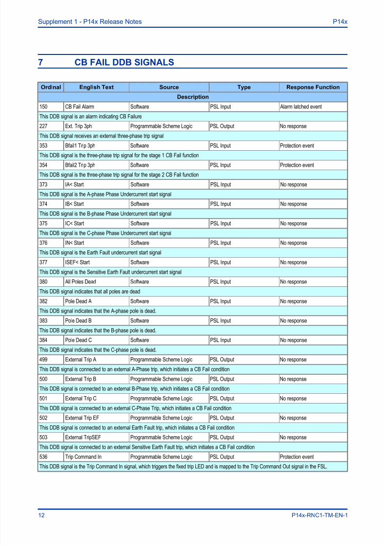
7 CB FAIL DDB SIGNALS
Ordinal English Text Source Type Response Function
Description
150 CB Fail Alarm Software PSL Input Alarm latched event
This DDB signal is an alarm indicating CB Failure
227 Ext. Trip 3ph Programmable Scheme Logic PSL Output No response
This DDB signal receives an external three-phase trip signal
353 Bfail1 Trip 3ph Software PSL Input Protection event
This DDB signal is the three-phase trip signal for the stage 1 CB Fail function
354 Bfail2 Trip 3ph Software PSL Input Protection event
This DDB signal is the three-phase trip signal for the stage 2 CB Fail function
373 IA< Start Software PSL Input No response
This DDB signal is the A-phase Phase Undercurrent start signal
374 IB< Start Software PSL Input No response
This DDB signal is the B-phase Phase Undercurrent start signal
375 IC< Start Software PSL Input No response
This DDB signal is the C-phase Phase Undercurrent start signal
376 IN< Start Software PSL Input No response
This DDB signal is the Earth Fault undercurrent start signal
377 ISEF< Start Software PSL Input No response
This DDB signal is the Sensitive Earth Fault undercurrent start signal
380 All Poles Dead Software PSL Input No response
This DDB signal indicates that all poles are dead
382 Pole Dead A Software PSL Input No response
This DDB signal indicates that the A-phase pole is dead.
383 Pole Dead B Software PSL Input No response
This DDB signal indicates that the B-phase pole is dead.
384 Pole Dead C Software PSL Input No response
This DDB signal indicates that the C-phase pole is dead.
499 External Trip A Programmable Scheme Logic PSL Output No response
This DDB signal is connected to an external A-Phase trip, which initiates a CB Fail condition
500 External Trip B Programmable Scheme Logic PSL Output No responseThis DDB signal is connected to an external B-Phase trip, which initiates a CB Fail condition
501 External Trip C Programmable Scheme Logic PSL Output No response
This DDB signal is connected to an external C-Phase Trip, which initiates a CB Fail condition
502 External Trip EF Programmable Scheme Logic PSL Output No response
This DDB signal is connected to an external Earth Fault trip, which initiates a CB Fail condition
503 External TripSEF Programmable Scheme Logic PSL Output No response
This DDB signal is connected to an external Sensitive Earth Fault trip, which initiates a CB Fail condition
536 Trip Command In Programmable Scheme Logic PSL Output Protection event
This DDB signal is the Trip Command In signal, which triggers the fixed trip LED and is mapped to the Trip Command Out signal in the FSL.
Supplement 1 - P14x Release Notes P14x
12 P14x-RNC1-TM-EN-1

8/11/2019 P14x RNC1 TM en 1 Release Notes
http://slidepdf.com/reader/full/p14x-rnc1-tm-en-1-release-notes 17/18

8/11/2019 P14x RNC1 TM en 1 Release Notes
http://slidepdf.com/reader/full/p14x-rnc1-tm-en-1-release-notes 18/18
Alstom Grid
© - ALSTOM 2013. All rights reserved.Information contained in this document is
indicative only. No representation or warranty is
given or should be relied on that it is complete or
correct or will apply to any particular project. This
will depend on the technical and commercial
circumstances. It is provided without liability and
is subject to change without notice.
Reproduction, use or disclosure to third parties,
without express written authority, is strictly
prohibited.
Alstom Grid Worldwide Contact Centre
www.alstom.com/grid/contactcentre/
Tel: +44 (0) 1785 250 070
www.alstom.com