P14031: Jib Transfer Bench - Rochester Institute of...
33
P14031: Jib Transfer Bench Matt Brunelle Nicole Conway Mike Kennedy Katy Wurman Sub-System Design 1
Transcript of P14031: Jib Transfer Bench - Rochester Institute of...
P14031: Jib Transfer Bench
Matt Brunelle
Nicole Conway
Mike Kennedy
Katy Wurman
Sub-System Design
1
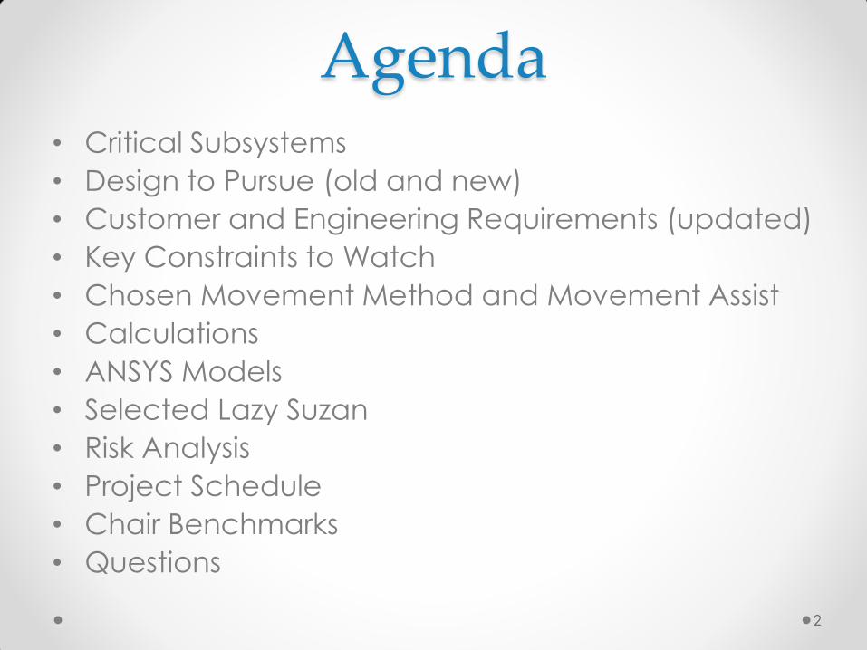
• Critical Subsystems
• Design to Pursue (old and new)
• Customer and Engineering Requirements (updated)
• Key Constraints to Watch
• Chosen Movement Method and Movement Assist
• Calculations
• ANSYS Models
• Selected Lazy Suzan
• Risk Analysis
• Project Schedule
• Chair Benchmarks
• Questions
2
Agenda
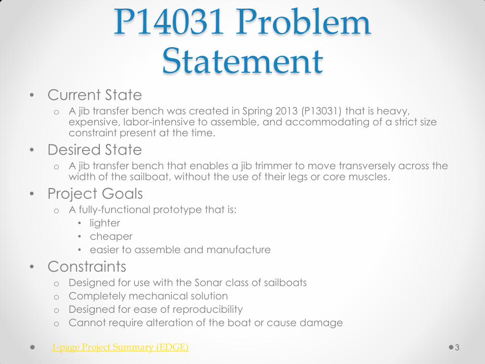
P14031 Problem Statement
• Current State o A jib transfer bench was created in Spring 2013 (P13031) that is heavy,
expensive, labor-intensive to assemble, and accommodating of a strict size constraint present at the time.
• Desired State o A jib transfer bench that enables a jib trimmer to move transversely across the
width of the sailboat, without the use of their legs or core muscles.
• Project Goals o A fully-functional prototype that is:
• lighter
• cheaper
• easier to assemble and manufacture
• Constraints o Designed for use with the Sonar class of sailboats
o Completely mechanical solution
o Designed for ease of reproducibility
o Cannot require alteration of the boat or cause damage
3 1-page Project Summary (EDGE)

• Why? o Most technically challenging
design elements
o Directly effect many of the
most important customer and
engineering requirements
4
• Movement method o Linear vs. rotational
• Movement assist o Gravity?
o Assist bar?
o Pulley or other systems?
Critical Subsystems
5
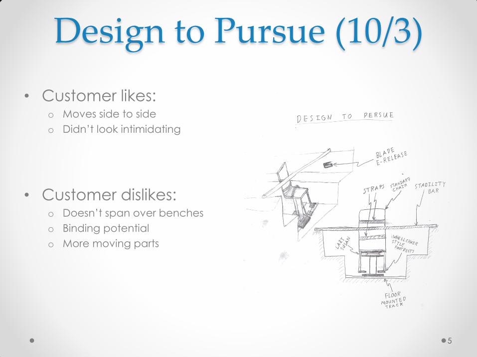
• Customer likes: o Moves side to side
o Didn’t look intimidating
• Customer dislikes: o Doesn’t span over benches
o Binding potential
o More moving parts
Design to Pursue (10/3)

6
• Advantages: o Simplicity
o Goes out over benches
• Disadvantages: o Moment is HUUUUUGGGE,
Rochester, HUUUUUUUGGE!!!!
Design to Pursue (10/15)
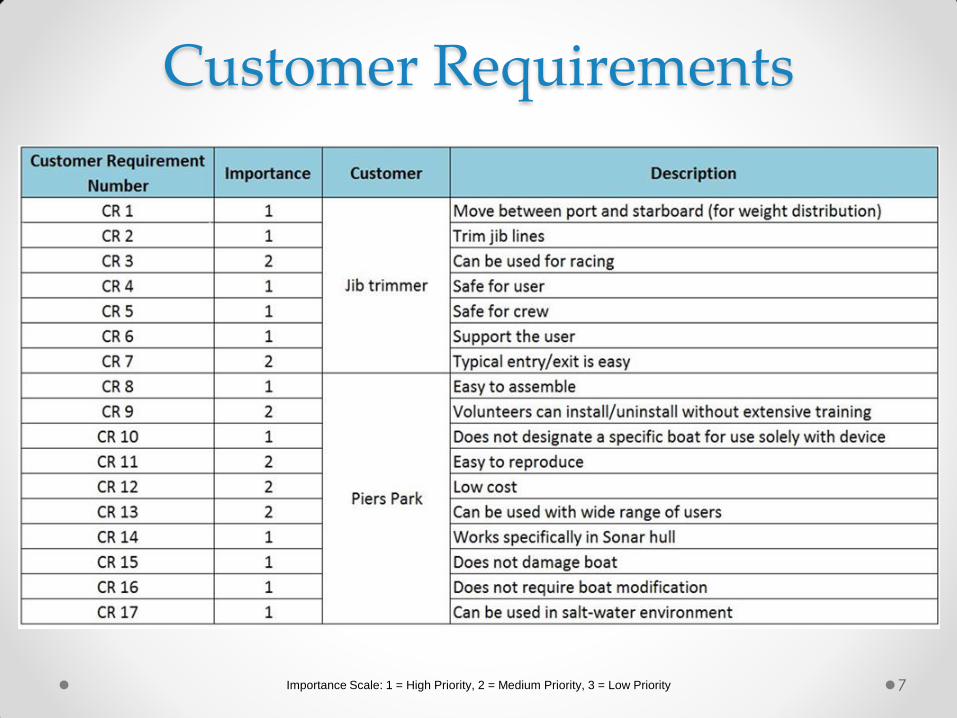
Importance Scale: 1 = High Priority, 2 = Medium Priority, 3 = Low Priority 7
Customer Requirements
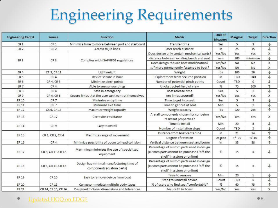
Engineering Requirements
8 Updated HOQ on EDGE
• Simple design! o We received feedback from Caitlyn at Piers Park that all previous
iterations were WAY over-engineered
• Easy installation
• Use with a wide range of users o Chair design/dimensions
o Movement assist devices
• An un-intimidating design
• Do not limit feeling of freedom by securing user too
much
• Budget decreased from $2,500 to $1,000
9
Key Constraints to Watch
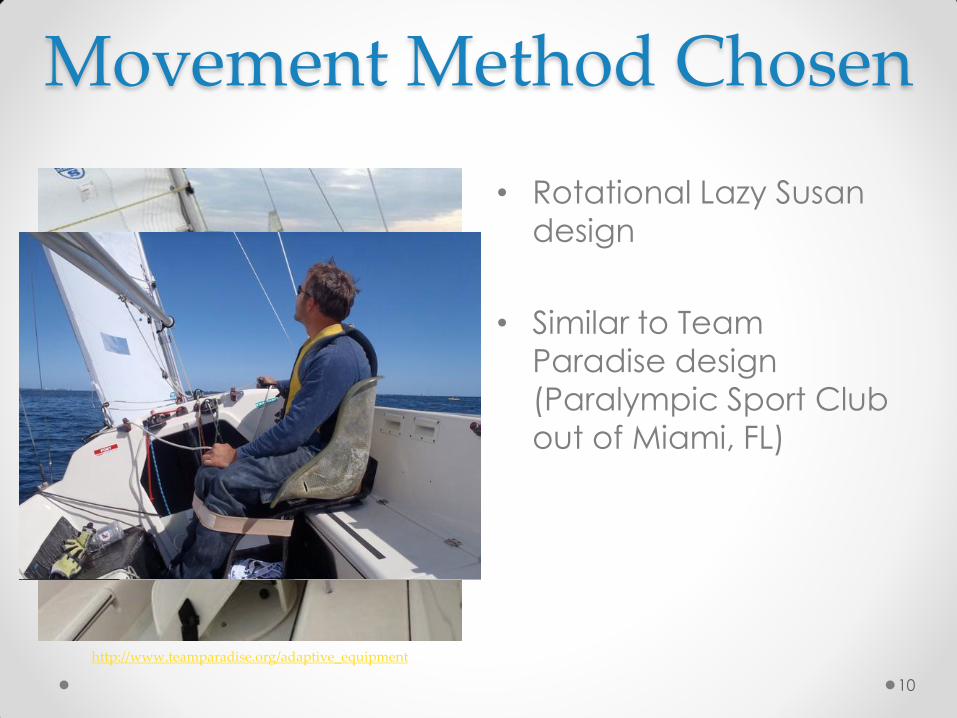
• Rotational Lazy Susan
design
• Similar to Team
Paradise design
(Paralympic Sport Club
out of Miami, FL)
10
Movement Method Chosen
http://www.teamparadise.org/adaptive_equipment
11
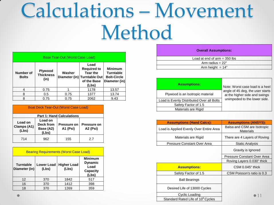
Calculations – Movement Method
Base Tear-Out (Worst Case Load)
Number of
Bolts
Plywood
Thickness
(in)
Washer
Diameter (in)
Load
Required to
Tear the
Turntable Out
of the Base
(Lbs)
Minimum
Turntable
Bolt-Circle
Diameter (in)
4 0.75 1 1178 13.57
8 0.5 0.75 1377 13.74
8 0.75 0.75 2062 9.43
Boat Deck Tear-Out (Worst Case Load)
Part 1: Hand Calculations
Load on
Clamps (A1)
(Lbs)
Load on
Deck from
Base (A2)
(Lbs)
Pressure on
A1 (Psi)
Pressure on
A2 (Psi)
714 962 155 2.7
Bearing Requirements (Worst Case Load)
Turntable
Diameter (in)
Lower Load
(Lbs)
Higher Load
(Lbs)
Minimum
Dynamic
Load
Capacity
(Lbs)
12 370 1842 517
16 370 1412 398
18 370 1269 359
Overall Assumptions:
Load at end of arm = 350 lbs
Arm radius = 22"
Arm height = 14"
Assumptions: Note: Worst case load is a heel
angle of 45 deg, the user starts
at the higher side and swings
unimpeded to the lower side.
Plywood is an Isotropic material
Load is Evenly Distributed Over all Bolts
Safety Factor of 1.5
Materials are Rigid
Assumptions (Hand Calcs): Assumptions (ANSYS):
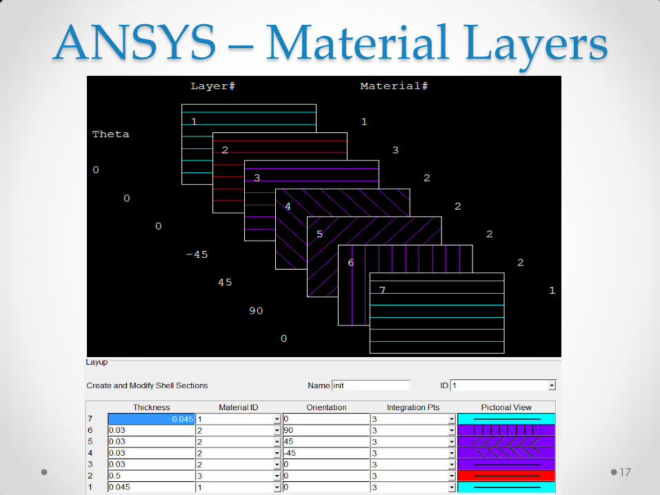
Load is Applied Evenly Over Entire Area Balsa and CSM are Isotropic
Materials
Materials are Rigid There are 4 Layers of Roving
Pressure Constant Over Area Static Analysis
Gravity is Ignored
Pressure Constant Over Area
Roving Layers 0.030" thick
Assumptions: CSM 0.045" thick
Safety Factor of 1.5 CSM Poisson's ratio is 0.3
Ball Bearings
Desired Life of 13000 Cycles
Cyclic Loading
Standard Rated Life of 106 Cycles
12
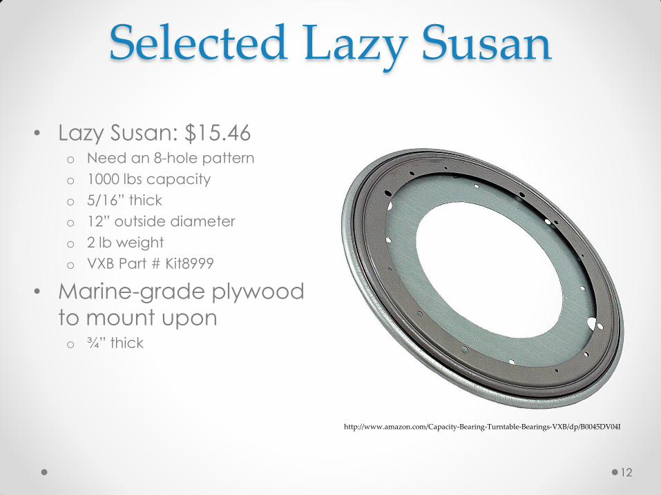
• Lazy Susan: $15.46 o Need an 8-hole pattern
o 1000 lbs capacity
o 5/16” thick
o 12” outside diameter
o 2 lb weight
o VXB Part # Kit8999
• Marine-grade plywood
to mount upon o ¾” thick
Selected Lazy Susan
http://www.amazon.com/Capacity-Bearing-Turntable-Bearings-VXB/dp/B0045DV04I
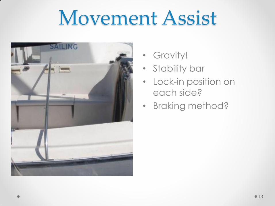
• Gravity!
• Stability bar
• Lock-in position on
each side?
• Braking method?
13
Movement Assist
14
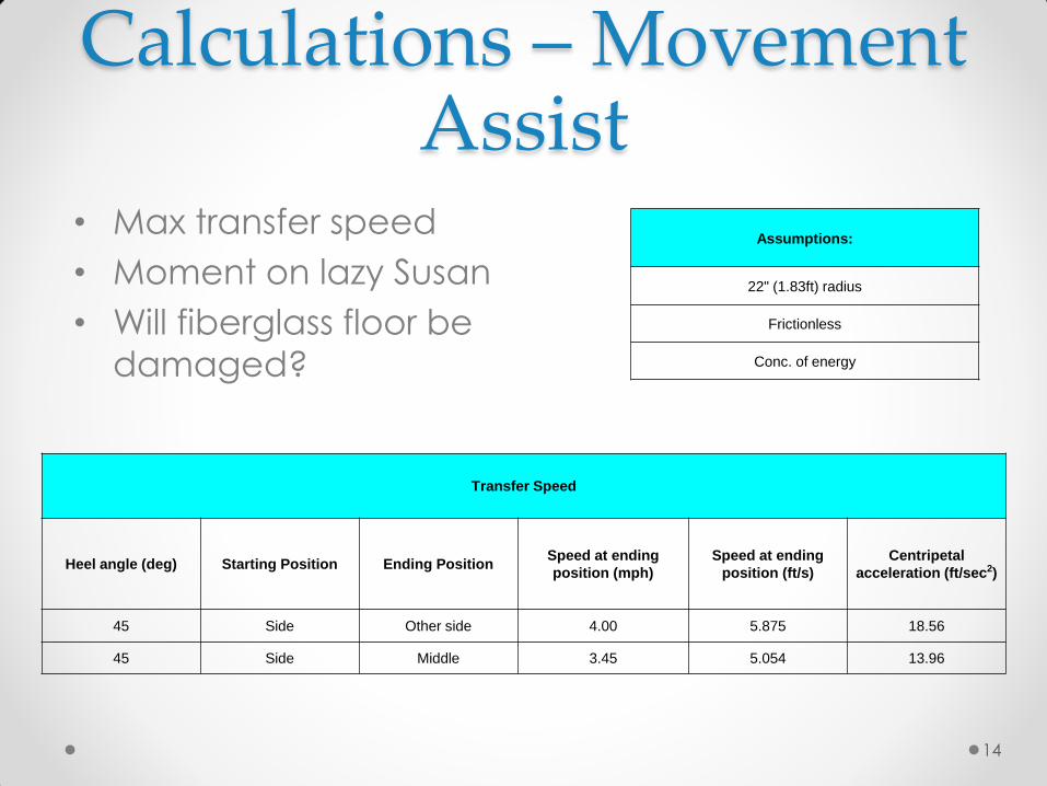
Transfer Speed
Heel angle (deg) Starting Position Ending Position Speed at ending
position (mph)
Speed at ending
position (ft/s)
Centripetal
acceleration (ft/sec2)
45 Side Other side 4.00 5.875 18.56
45 Side Middle 3.45 5.054 13.96
• Max transfer speed
• Moment on lazy Susan
• Will fiberglass floor be
damaged?
Calculations – Movement Assist
Assumptions:
22" (1.83ft) radius
Frictionless
Conc. of energy
15
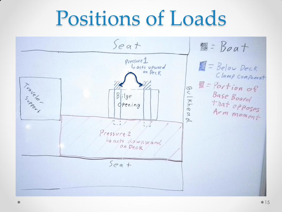
Positions of Loads
16
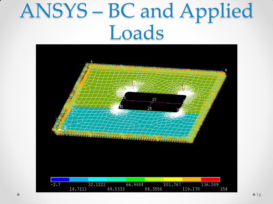
ANSYS – BC and Applied Loads
17
ANSYS – Material Layers
18
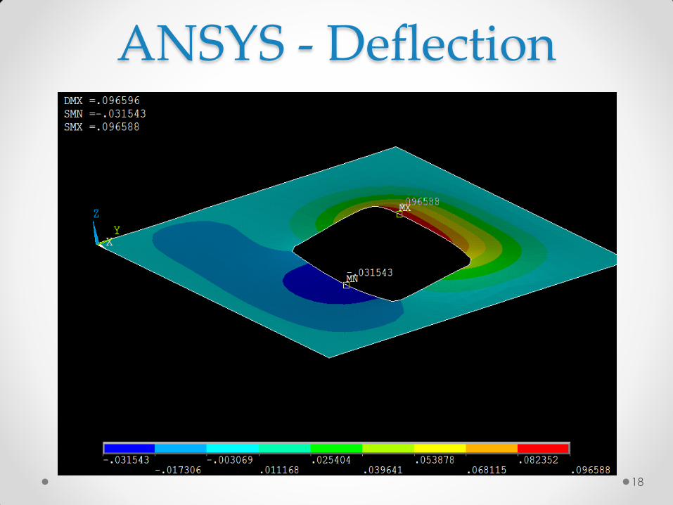
ANSYS - Deflection
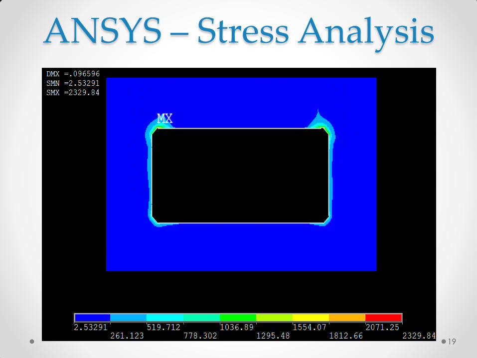
19
ANSYS – Stress Analysis
Risk
Number Risk Cause (why it happens) Effects Severity Probability
Hazard
Score
Actions to reduce failure
mode
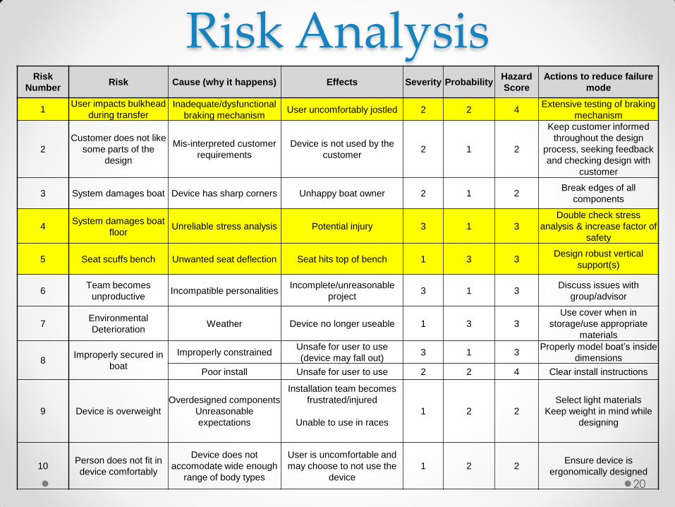
1 User impacts bulkhead
during transfer Inadequate/dysfunctional
braking mechanism User uncomfortably jostled 2 2 4
Extensive testing of braking
mechanism
2
Customer does not like
some parts of the
design
Mis-interpreted customer
requirements
Device is not used by the
customer 2 1 2
Keep customer informed
throughout the design
process, seeking feedback
and checking design with
customer
3 System damages boat Device has sharp corners Unhappy boat owner 2 1 2 Break edges of all
components
4 System damages boat
floor Unreliable stress analysis Potential injury 3 1 3
Double check stress
analysis & increase factor of
safety
5 Seat scuffs bench Unwanted seat deflection Seat hits top of bench 1 3 3 Design robust vertical
support(s)
6 Team becomes
unproductive Incompatible personalities
Incomplete/unreasonable
project 3 1 3
Discuss issues with
group/advisor
7 Environmental
Deterioration Weather Device no longer useable 1 3 3
Use cover when in
storage/use appropriate
materials
8 Improperly secured in
boat
Improperly constrained Unsafe for user to use
(device may fall out) 3 1 3
Properly model boat’s inside
dimensions
Poor install Unsafe for user to use 2 2 4 Clear install instructions
9 Device is overweight
Overdesigned components
Unreasonable
expectations
Installation team becomes
frustrated/injured
Unable to use in races
1 2 2
Select light materials
Keep weight in mind while
designing
10 Person does not fit in
device comfortably
Device does not
accomodate wide enough
range of body types
User is uncomfortable and
may choose to not use the
device
1 2 2 Ensure device is
ergonomically designed
20
Risk Analysis
Risk
Number Risk Cause (why it happens) Effects Severity Probability
Hazard
Score Actions to reduce failure mode
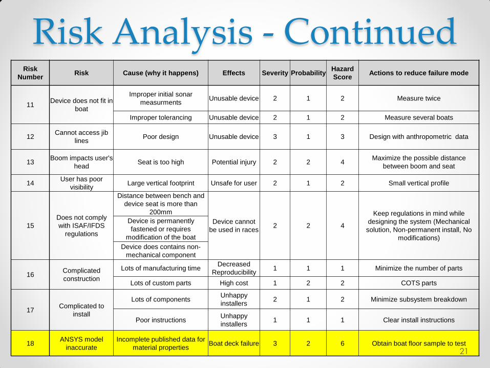
11 Device does not fit in
boat
Improper initial sonar
measurments Unusable device 2 1 2 Measure twice
Improper tolerancing Unusable device 2 1 2 Measure several boats
12 Cannot access jib
lines Poor design Unusable device 3 1 3 Design with anthropometric data
13 Boom impacts user's
head Seat is too high Potential injury 2 2 4
Maximize the possible distance
between boom and seat
14 User has poor
visibility Large vertical footprint Unsafe for user 2 1 2 Small vertical profile
15
Does not comply
with ISAF/IFDS
regulations
Distance between bench and
device seat is more than
200mm
Device cannot
be used in races 2 2 4
Keep regulations in mind while
designing the system (Mechanical
solution, Non-permanent install, No
modifications)
Device is permanently
fastened or requires
modification of the boat
Device does contains non-
mechanical component
16 Complicated
construction
Lots of manufacturing time Decreased
Reproducibility 1 1 1 Minimize the number of parts
Lots of custom parts High cost 1 2 2 COTS parts
17 Complicated to
install
Lots of components Unhappy
installers 2 1 2 Minimize subsystem breakdown
Poor instructions Unhappy
installers 1 1 1 Clear install instructions
18 ANSYS model
inaccurate
Incomplete published data for
material properties Boat deck failure 3 2 6 Obtain boat floor sample to test
21
Risk Analysis - Continued
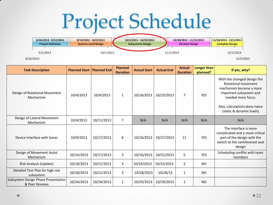
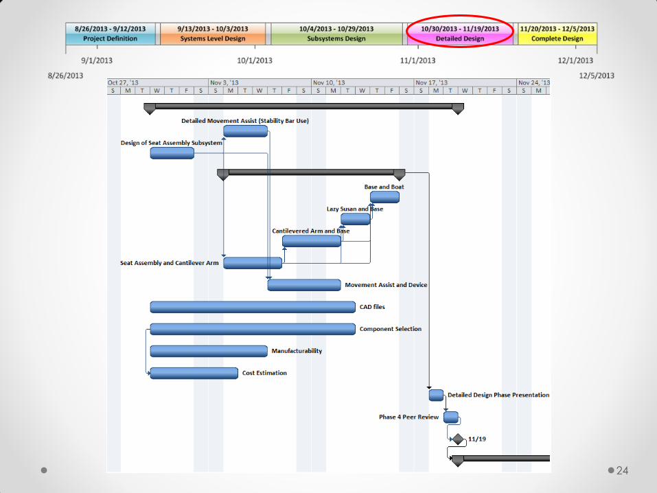
Project Schedule
22
Task Description Planned Start Planned End Planned Duration
Actual Start Actual End Actual
Duration Longer than
planned? If yes, why?
Design of Rotational Movement Mechanism
10/4/2013 10/4/2013 1 10/16/2013 10/23/2013 7 YES
With the changed design the Rotational movement
mechanism became a more important subsystem and
needed more focus.
Also, calculations done twice (static & dynamic loads)
Design of Lateral Movement Mechanism
10/4/2013 10/11/2013 7 N/A N/A N/A N/A N/A
Device Interface with Sonar 10/9/2013 10/17/2013 8 10/16/2013 10/27/2013 11 YES
The interface is more complicated and a more critical
part of the design with the switch to the cantilevered seat
design
Design of Movement Assist Mechanism
10/14/2013 10/17/2013 3 10/16/2013 10/21/2013 5 YES Scheduling conflits with team
members
Risk Analysis (Update) 10/18/2013 10/21/2013 3 10/24/2013 10/25/2013 2 NO
Detailed Test Plan for high risk subsystem
10/18/2013 10/21/2013 3 10/28/2013 10/28/13 1 NO
Subsystem Design Phase Presentation & Peer Reviews
10/24/2013 10/24/2013 1 10/29/2013 10/29/2013 1 NO
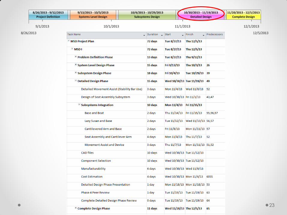
23
24
25
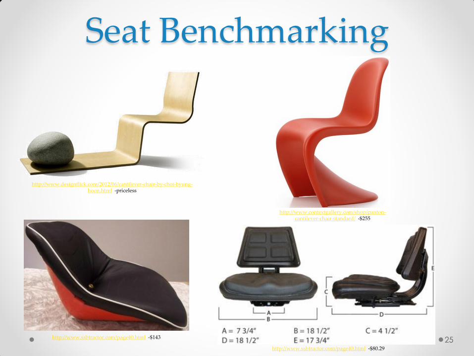
http://www.designflick.com/2012/06/cantilever-chair-by-choi-byung-hoon.html -priceless
http://www.contextgallery.com/shop/panton-cantilever-chair-standard/ -$255
http://www.ssbtractor.com/page40.html -$143
Seat Benchmarking
http://www.ssbtractor.com/page40.html -$80.29
26
http://photo.americascup.com/25-09-2013-San-Francisco-USA-CA-34th-America-s-Cup-,en,igf1724p96n53.html
Questions?
• http://www.teamparadise.org/adaptive_equipmen
t/ls2-sonar.html#previous-photo
• http://www.teamparadise.org/adaptive_equipmen
t/ls2-sonar.html#previous-photo
• http://www.teamparadise.org/adaptive_equipmen
t/sonar2.html#previous-photo
27
Credits
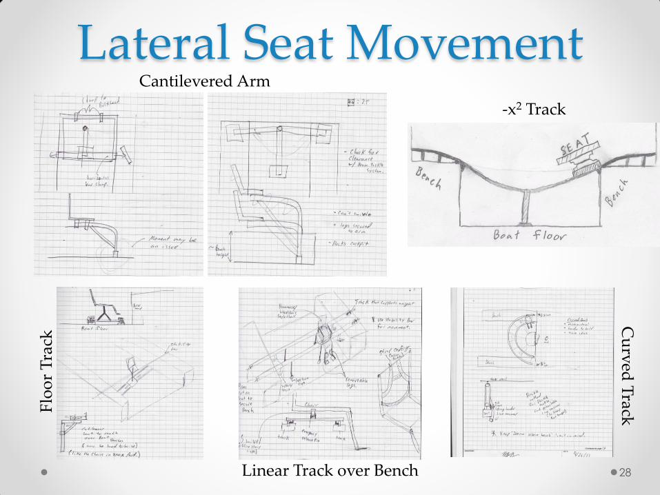
Lateral Seat Movement Cantilevered Arm
Cu
rved
Track
Linear Track over Bench
-x2 Track
Flo
or
Tra
ck
28
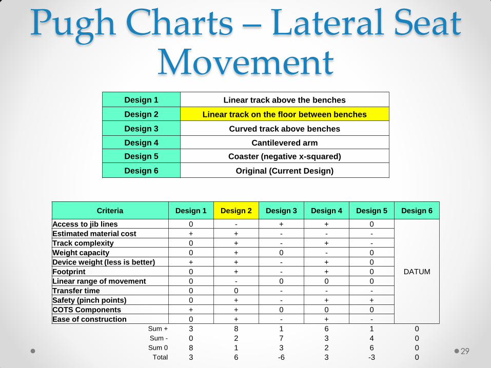
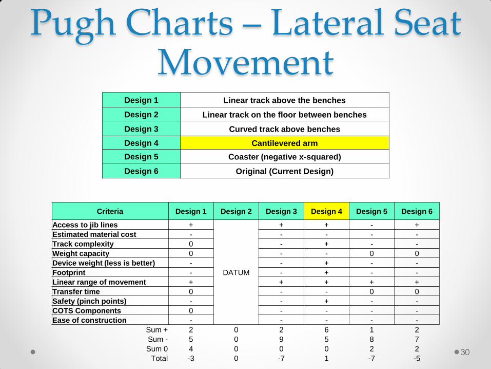
Pugh Charts – Lateral Seat Movement
Design 1 Linear track above the benches
Design 2 Linear track on the floor between benches
Design 3 Curved track above benches
Design 4 Cantilevered arm
Design 5 Coaster (negative x-squared)
Design 6 Original (Current Design)
Criteria Design 1 Design 2 Design 3 Design 4 Design 5 Design 6
Access to jib lines 0 - + + 0
DATUM
Estimated material cost + + - - -
Track complexity 0 + - + -
Weight capacity 0 + 0 - 0
Device weight (less is better) + + - + 0
Footprint 0 + - + 0
Linear range of movement 0 - 0 0 0
Transfer time 0 0 - - -
Safety (pinch points) 0 + - + +
COTS Components + + 0 0 0
Ease of construction 0 + - + -
Sum + 3 8 1 6 1 0
Sum - 0 2 7 3 4 0
Sum 0 8 1 3 2 6 0
Total 3 6 -6 3 -3 0 29
Pugh Charts – Lateral Seat Movement
Design 1 Linear track above the benches
Design 2 Linear track on the floor between benches
Design 3 Curved track above benches
Design 4 Cantilevered arm
Design 5 Coaster (negative x-squared)
Design 6 Original (Current Design)
Criteria Design 1 Design 2 Design 3 Design 4 Design 5 Design 6
Access to jib lines +
DATUM
+ + - +
Estimated material cost - - - - -
Track complexity 0 - + - -
Weight capacity 0 - - 0 0
Device weight (less is better) - - + - -
Footprint - - + - -
Linear range of movement + + + + +
Transfer time 0 - - 0 0
Safety (pinch points) - - + - -
COTS Components 0 - - - -
Ease of construction - - - - -
Sum + 2 0 2 6 1 2
Sum - 5 0 9 5 8 7
Sum 0 4 0 0 0 2 2
Total -3 0 -7 1 -7 -5 30
31
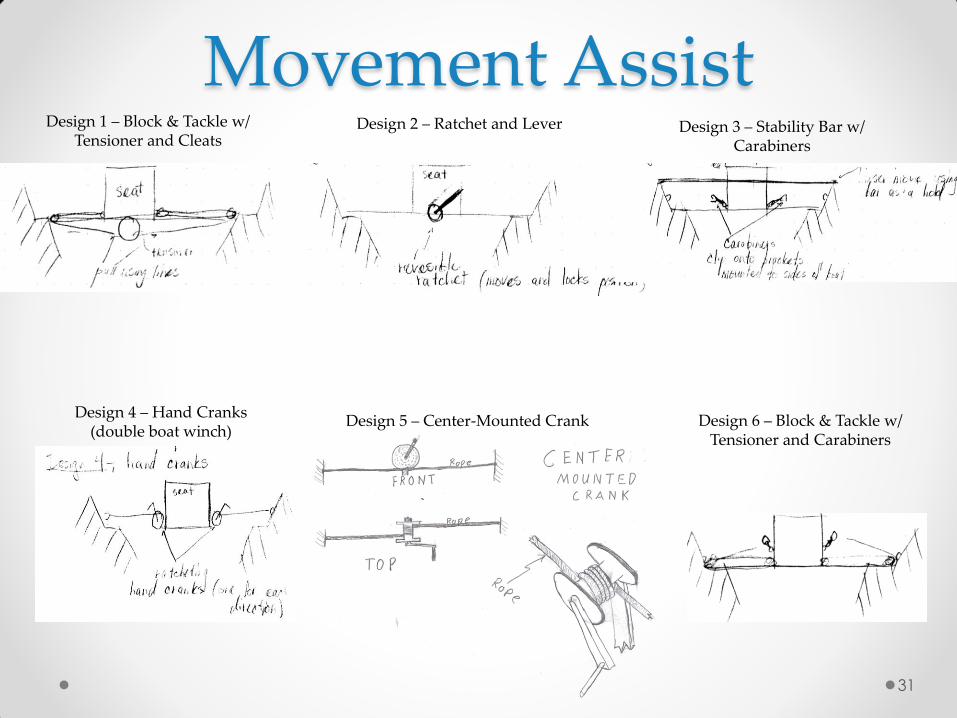
Movement Assist Design 2 – Ratchet and Lever Design 1 – Block & Tackle w/
Tensioner and Cleats Design 3 – Stability Bar w/
Carabiners
Design 4 – Hand Cranks (double boat winch)
Design 6 – Block & Tackle w/ Tensioner and Carabiners
Design 5 – Center-Mounted Crank
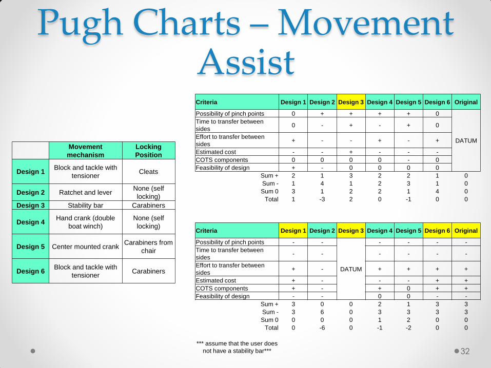
Pugh Charts – Movement Assist Criteria Design 1 Design 2 Design 3 Design 4 Design 5 Design 6 Original
Possibility of pinch points 0 + + + + 0
DATUM
Time to transfer between
sides 0 - + - + 0
Effort to transfer between
sides + - - + - +
Estimated cost - - + - - -
COTS components 0 0 0 0 - 0
Feasibility of design + - 0 0 0 0
Sum + 2 1 3 2 2 1 0
Sum - 1 4 1 2 3 1 0
Sum 0 3 1 2 2 1 4 0
Total 1 -3 2 0 -1 0 0
Criteria Design 1 Design 2 Design 3 Design 4 Design 5 Design 6 Original
Possibility of pinch points - -
DATUM
- - - -
Time to transfer between
sides - - - - - -
Effort to transfer between
sides + - + + + +
Estimated cost + - - - + +
COTS components + - + 0 + +
Feasibility of design - - 0 0 - -
Sum + 3 0 0 2 1 3 3
Sum - 3 6 0 3 3 3 3
Sum 0 0 0 0 1 2 0 0
Total 0 -6 0 -1 -2 0 0
*** assume that the user does
not have a stability bar***
Movement
mechanism
Locking
Position
Design 1 Block and tackle with
tensioner Cleats
Design 2 Ratchet and lever None (self
locking)
Design 3 Stability bar Carabiners
Design 4 Hand crank (double
boat winch)
None (self
locking)
Design 5 Center mounted crank Carabiners from
chair
Design 6 Block and tackle with
tensioner Carabiners
32
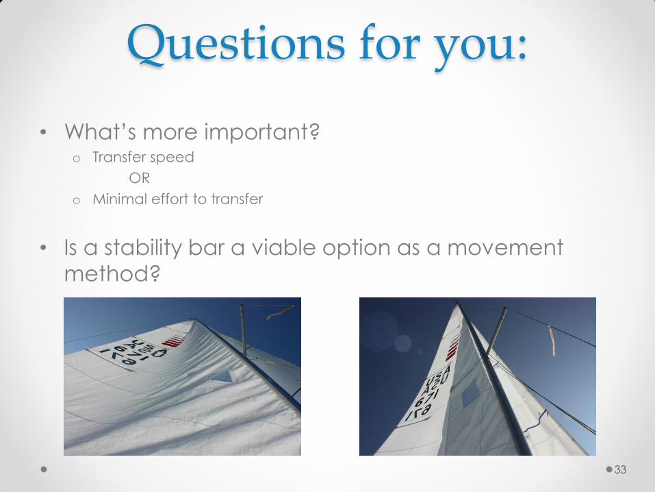
• What’s more important? o Transfer speed
OR
o Minimal effort to transfer
• Is a stability bar a viable option as a movement
method?
Questions for you:
33


![Pillar and wall-mounted slewing jib cranes · Max. load capacity [kg] Electric slewing Pillar-mounted slewing jib cranes Wall-mounted slewing jib cranes Jib type/design Max. outreach](https://static.fdocuments.us/doc/165x107/5b535fa87f8b9ae30b8be93d/pillar-and-wall-mounted-slewing-jib-cranes-max-load-capacity-kg-electric.jpg)