P10505 – Cold Pressure Fusing II System Design Review Team Fusion 1/15/2010.
29
P10505 – Cold Pressure Fusing II System Design Review Team Fusion 1/15/2010
-
Upload
jeffry-ray -
Category
Documents
-
view
216 -
download
0
Transcript of P10505 – Cold Pressure Fusing II System Design Review Team Fusion 1/15/2010.

P10505 – Cold Pressure Fusing IISystem Design Review
Team Fusion1/15/2010
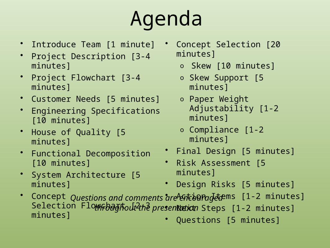
Agenda• Introduce Team [1 minute]• Project Description [3-4 minutes]• Project Flowchart [3-4 minutes]• Customer Needs [5 minutes]• Engineering Specifications [10
minutes]• House of Quality [5 minutes]• Functional Decomposition [10
minutes]• System Architecture [5 minutes]• Concept Selection Flowchart [2-3
minutes]
• Concept Selection [20 minutes]o Skew [10 minutes]o Skew Support [5 minutes]o Paper Weight Adjustability [1-2
minutes]o Compliance [1-2 minutes]
• Final Design [5 minutes]• Risk Assessment [5 minutes]• Design Risks [5 minutes]• Action Items [1-2 minutes]• Next Steps [1-2 minutes]• Questions [5 minutes]
Questions and comments are encouraged throughout the presentation

Project Team, Faculty, & Customer
• Project Memberso Aniket Arora – Project Manager – ISEo David Hatch – Lead Engineer – MEo Jon Burville – MEo Eric Wilcox – MEo Tom Stojanov – EE
• Customero Mr. John Knapp - Xeroxo Mr. Tony Condello - Xerox
• Faculty Guide o Mr. Bill Nowak - Xerox

Project Background/Description• Changing customer
expectations from printers.
• Focus on sustainability (low energy consumption).• Energy Star
• Heat fusing consumes a considerable portion of energy.• Hence, Cold Pressure
Fusing.
• P09505 developed an initial prototype.• Issues with pressure
uniformity

MSD 1
Research Past work
Patent Research
Past work from P09505
Establishing Customer
Needs
Concept Selection
Generation Pugh Concept Selection
Concept Improvement Modeling
Calculate Nip Pressure
Analyze Roller Deflection
Torsion Analysis
Create CAD Model DAQ System
Create Real-time DAQ
System
Interface DAQ with hardware
Present Design
Project Planning
Project Schedule WBS
Project Flowchart MSD 1

Customer Needs

Customer Needs

Engineering SpecificationsEngr. Spec. # Importance Source Specification (description) Unit of Measure Marginal Value Ideal Value
ES1 1 Customer Need Prototype will fuse print across 100% of the pagePercentage fused, Width of unfused, N/A 100% fusing
ES2 1 Customer Need Prototype will vary in nip pressure less than 10%
Width of Pressure Indication, Xerox
Metric 10% variation 5% variation
ES3 1 Customer NeedPrototype must be capable of adjusting to three skew angles Number of Settings 2 angles Analog
ES4 1 Customer NeedPrototype must adhere to Abaqus model created by Xerox Yes/No N/A Yes
ES5 1 Customer Need Prototype must be able to reach a 1.9° skew angle Degrees 1.8°-2.0° 1.9°
ES6 1 Customer NeedPrototype must be adjustable to the same skew angle to a 1/10th degree for ~25 runs Standard Deviation 1/5th degree variation
1/10th degree variation
ES7 1 Customer Need
Prototype must accommodate 120gsm (80# text) Digital Color Elite Gloss coated media while meeting all other specifications Yes/No N/A
Accomodates all paper weights
ES8 2 Customer Need Prototype will minimally calendar print Qualitative Moderate None
ES9 2 Customer NeedPrototype will produce trailing edge wrinkles less than once every twenty prints Number
1 wrinkle every 10 prints No wrinkles ever
ES11 3 Implied Prototype must be stable for a load of 4000 psi Force Vibration Stationary
ES10 3 Customer Need Feed rate must not decrease by more than 5% Torque10% reduction of
speed5% reduction of
speed
ES12 3 Implied Prototype must be manufacturable within ~2 week Time Required, Y/N 4 weeks 2 week
ES13 3 ImpliedPrototype will take less than 60 secs of user time to set up print Time Required 120 sec 0 secs
ES14 3 ImpliedPrototype must be able to print >1000 copies without failure
Life Cycle (Number of Prints) 500 copies 1000
ES15 4 Customer Need Prototype must cost less than $3000 Dollars $3,000 $1,500


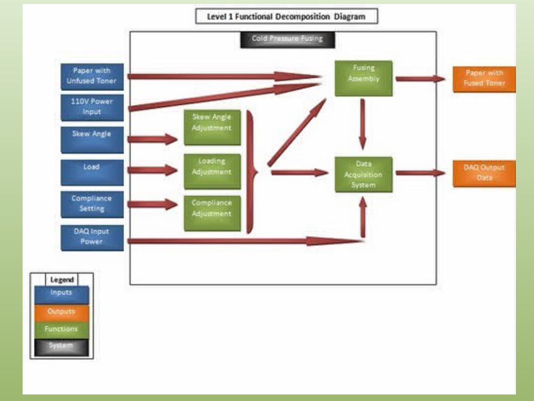


System Architecture

Assessing Customer Needs
Brainstorming ideas to meet
needs
First Concept selection
Skew Adjustment
Mechanism of Adjustment
Support of Adjustment
Paperweight adjustment Compliance
Concept Selection Flowchart
Swapping Pillow Blocks Saw Tooth Crank Adjustment Sliding Channel Frictional Coating
Hook and Pinion Bolts
Bolts and Ridged Channel
Swapping End Blocks
Adjustable End Blocks
End Blocks with Multiple holes
Push Bolt Pull Bolt in channel
Pull Shelf with Bolt
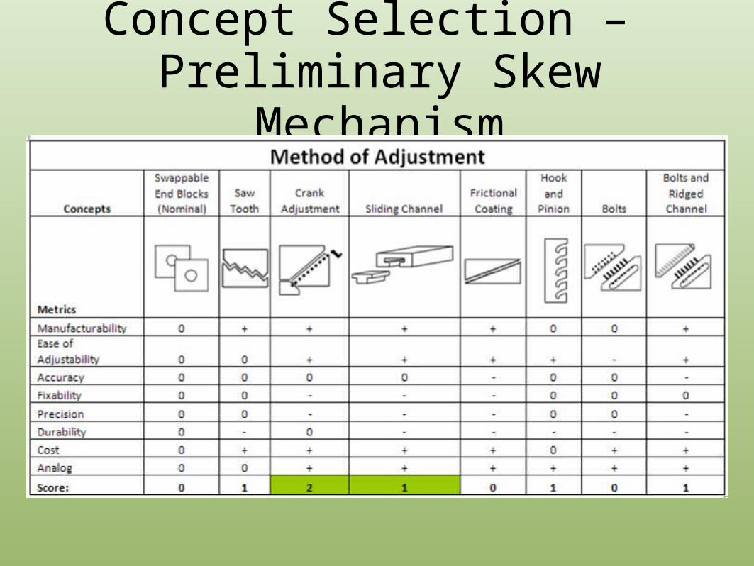
Concept Selection – Preliminary Skew Mechanism

Concept Selection – Secondary Skew Mechanism
Skew Adjustment
Concepts Swappable End Blocks Adjustable End Blocks End Blocks with Multiple Holes
Metrics
Cost 0 + 0
Fixability 0 0 -
Manufacturability 0 + 0
Durability 0 - -
Skew Alignment 0 ++ 0
Complexity 0 - 0
Ease of Assembly 0 - 0
Score: 0 1 -2

Preliminary Concept CAD Models
Figure 1. Side view of End Block

Preliminary Concept CAD Assembly
Figure 2. Assembly Model

Concept Selection – Skew Support
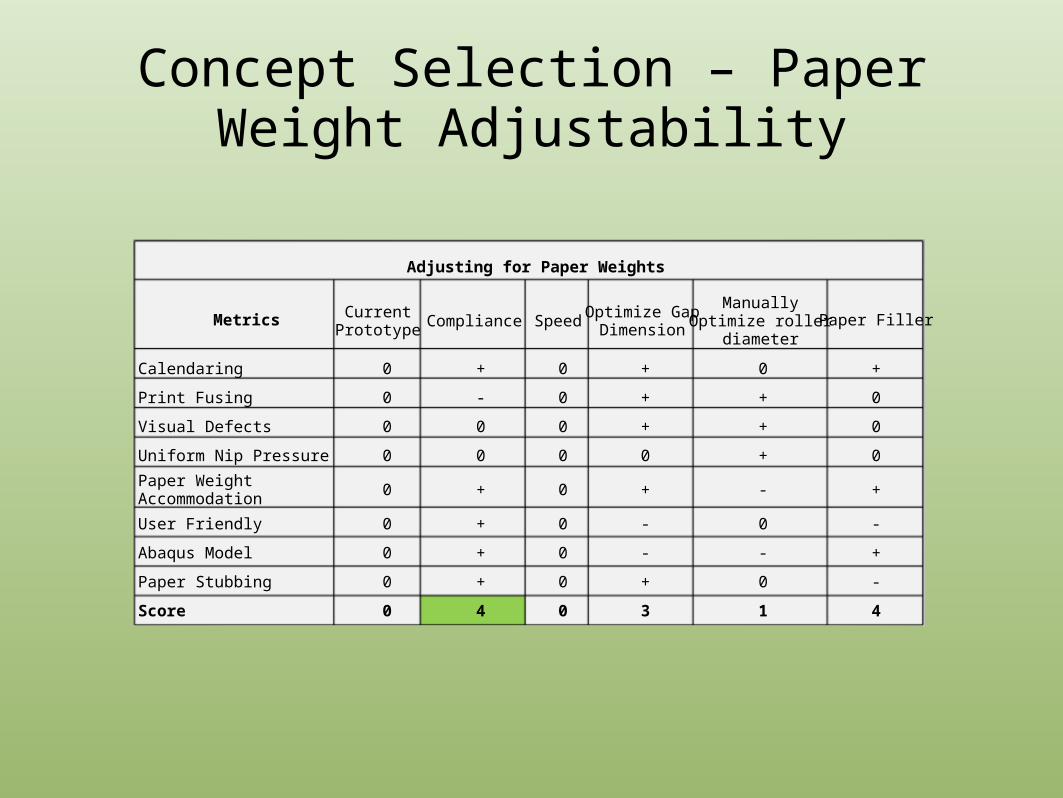
Adjusting for Paper Weights
Metrics Current Prototype
Compliance SpeedOptimize Gap
DimensionManually Optimize
roller diameterPaper Filler
Calendaring 0 + 0 + 0 +
Print Fusing 0 - 0 + + 0
Visual Defects 0 0 0 + + 0
Uniform Nip Pressure 0 0 0 0 + 0
Paper Weight Accommodation 0 + 0 + - +
User Friendly 0 + 0 - 0 -
Abaqus Model 0 + 0 - - +
Paper Stubbing 0 + 0 + 0 -
Score 0 4 0 3 1 4
Concept Selection – Paper Weight Adjustability

Metrics Washers (Various
Materials) Springs Coated Elastomer
Rollers Manually Adjust
Pressure Hydraulics
Cost 2 2 1 3 1
Durability 2 2 Constraint 3 1
Load Strength 2 2 1 3 2
Complexity 3 3 1 3 1 Ease of Construction 3 3 1 3 1 Ease of Operation 3 3 3 1 3
Total: 15 15 7 16 9
Concept Selection - Compliance

Final Design

Risk Assessment


Design Risk Assessment

Action Items
• Action Items:o Eric: Model Detailed CAD Modelso David: ANSYSo Aniket: DOE Planningo Tom: DAQ Systemo Jon: Calculate Nip Pressure and Deflection

Next Steps Week 5 (1/11-1/17) Week 6 (1/18-1/24) Week 7 (1/25-1/31)
Midweek Friday Midweek Friday Midweek Friday
Midterm Design Review
Purchase Components as Confirmed
Calculate Nip pressure
Analyze Roller Deflection
Torsion Analysis
Create CAD Model
Create Real-time Data Acquisition system
Interface DAQ with Hardware
Create Test Plan
Review and Improve on System Design


![Endrich News Oktober 2017 dt+engl · Type C 2.5 W PERFORMANCE TYPE FUSING POWER [ FUSING TIME. ] ANCE FUSING PERFORMANCE FUSING PERFORMANCE Please note that this device](https://static.fdocuments.us/doc/165x107/5f68c7cca7d617432e4d41da/endrich-news-oktober-2017-dtengl-type-c-25-w-performance-type-fusing-power-fusing.jpg)