
P1 Companion Standard - Domotica Forumfiles.domoticaforum.eu/uploads/Smartmetering/DSMR v4.0 final...
23
Page 1 of 23 File name: Dutch Smart Meter Requirements v4.0 final P1.doc Date: 22-04-2011 Author: Netbeheer Nederland Version: 4.0 Final P1 Companion Standard Dutch Smart Meter Requirements By order of:Netbeheer Nederland Date: April 22 nd , 2011 Version: 4.0 Status: Final
Transcript of P1 Companion Standard - Domotica Forumfiles.domoticaforum.eu/uploads/Smartmetering/DSMR v4.0 final...

Page 1 of 23
File name: Dutch Smart Meter Requirements v4.0 final P1.doc Date: 22-04-2011 Author: Netbeheer Nederland Version: 4.0 Final
P1 Companion Standard Dutch Smart Meter Requirements
By order of:Netbeheer Nederland
Date: April 22nd, 2011
Version: 4.0
Status: Final

Page 2 of 23
File name: Dutch Smart Meter Requirements v4.0 final P1.doc Date: 22-04-2011 Author: Netbeheer Nederland Version: 4.0 Final
Change summary Version Change 4.0 The P1 document has been rewritten to such an extent that it was not
feasible to include all individual changes in this document. It is advised to read the new P1 document in its entirety.
Page 3 of 23
File name: Dutch Smart Meter Requirements v4.0 final P1.doc Date: 22-04-2011 Author: Netbeheer Nederland Version: 4.0 Final
CONTENTS
1 Introduction .......................................................................................................... 4 1.1 Scope................................................................................................................... 4
2 System architecture ............................................................................................. 5
3 Normative References ......................................................................................... 5
4 Physical Interface Characteristics ........................................................................ 6 4.1 Galvanic Isolation................................................................................................. 6 4.2 Power supply ....................................................................................................... 6 4.3 Connection........................................................................................................... 6 4.4 Addressing the measuring device ........................................................................ 6 4.5 Measuring device transfer time ............................................................................ 7 4.6 Signals ................................................................................................................. 7 4.7 Physical connector ............................................................................................... 7
5 Protocol Description ............................................................................................. 8 5.1 Transfer speed and character formatting.............................................................. 8 5.2 Data readout ........................................................................................................ 8 5.3 End of transmission.............................................................................................. 8 5.4 Representation of COSEM objects....................................................................... 9 5.5 Representation of COSEM Data Type octet-string (tag 9) ...................................10 5.6 Representation of COSEM Data Type bit-string (tag 4).......................................10 5.7 Representation of COSEM Data Type boolean ...................................................10 5.8 Representation of COSEM Data Type enum.......................................................10 5.9 Representation of COSEM objects......................................................................11 5.10 Representation of M-Bus values .........................................................................11 5.11 Representation of Profile Generic – Power failure logs .......................................11 5.12 Representation of P1 telegram............................................................................12 5.13 Example P1 telegram..........................................................................................16
6 Data objects........................................................................................................18 6.1 Electricity data.....................................................................................................18 6.2 Messages ...........................................................................................................18 6.3 Gas Data.............................................................................................................20 Thermal Data ......................................................................................................20 6.4 20 6.5 Water Data..........................................................................................................20 6.6 M-Bus Data of a fourth M-Bus device (for example a slave E-meter to measure
electricity production) ..........................................................................................21 6.7 Change of M-Bus device.....................................................................................21
7 Document list ......................................................................................................22
Hub basic Schematic data lines ..........................................................................23
Appendix I 23
Page 4 of 23
File name: Dutch Smart Meter Requirements v4.0 final P1.doc Date: 22-04-2011 Author: Netbeheer Nederland Version: 4.0 Final
1 INTRODUCTION 1.1 Scope
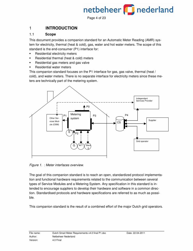
This document provides a companion standard for an Automatic Meter Reading (AMR) sys-tem for electricity, thermal (heat & cold), gas, water and hot water meters. The scope of this standard is the end-consumer (P1) interface for: � Residential electricity meters � Residential thermal (heat & cold) meters � Residential gas meters and gas valve � Residential water meters This companion standard focuses on the P1 interface for gas, gas valve, thermal (heat / cold), and water meters. There is no separate interface for electricity meters since these me-ters are technically part of the metering system.
Figure 1. : Meter interfaces overview. The goal of this companion standard is to reach an open, standardized protocol implementa-tion and functional hardware requirements related to the communication between several types of Service Modules and a Metering System. Any specification in this standard is in-tended to encourage suppliers to develop their hardware and software in a common direc-tion. Standardised protocols and hardware specifications are referred to as much as possi-ble. This companion standard is the result of a combined effort of the major Dutch grid operators.
CS
Independent Services Provider
Supplier
Grid operator
P1
G
E
Metering system Other Ser-
vices Mod-ule (OSM)
W/T
P3
P2
P4
P0
Slave E

Page 5 of 23
File name: Dutch Smart Meter Requirements v4.0 final P1.doc Date: 22-04-2011 Author: Netbeheer Nederland Version: 4.0 Final
2 SYSTEM ARCHITECTURE The interface is based on the following: � Simple installation by customer; � Simple and clearly defined interface; � Low cost for the installation itself; � Low cost for the customer installing, operating and maintaining the interface; � Safe for the customer; � The metering system or the data in it cannot be compromised. The interface is based on NEN-EN-IEC 62056-21 (Electrical metering-Data exchange for me-ter reading, tariff and load control – Part 21: direct local data exchange, 2002-05). Functional and technical requirements are given in the NTA 8130 document (see section 3). This companion standard holds physical characteristics and protocol definitions for the inter-face.
3 NORMATIVE REFERENCES The following standards are referred to in this company standard. For undated references the latest edition applies. Ref.No. Document Description
1. IEC 62056-21 Electricity metering – Data exchange for meter reading, tariff and load control – Part 21: Direct local data exchange
2. IEC 62056-61 Electricity metering - Data exchange for meter reading, tariff and load control – Part 61: OBIS Object Identification System
3. NTA 8130 NL:2007 Basisfuncties voor de meetinrichting voor elektriciteit, gas en thermische energie voor kleinverbruikers
4. DSMR 4.0 Dutch Smart Meter Requirements Version 4.0
5. AmvB
Algemene maatregel van Bestuur “Besluit op afstand uitleesbare meet- inrichtingen”
Table 3-1: Normative References
Page 6 of 23
File name: Dutch Smart Meter Requirements v4.0 final P1.doc Date: 22-04-2011 Author: Netbeheer Nederland Version: 4.0 Final
4 PHYSICAL INTERFACE CHARACTERISTICS The interface must be energy efficient and protected against fraud, OVP and ESD.
4.1 Galvanic Isolation
To protect the Metering System against reversed connection and over-voltage, and to lower the possibility of influencing the Metering System through the P1 port, the data lines of the P1 port will be equipped with an opto-coupler. The opto-coupler must adhere to the relevant legislation and standards for measuring equipment. . The power lines are galvanicly isolated from the power supply that powers the other parts of the meter. 4.2 Power supply
The power supply for the P1 port shall be able to withstand short circuits. Manipulation of the power supply lines shall never influence any other part of the meter, When no device is connected through the P1 port, the power consumption of the P1 circuitry shall not be included in the register values. When a device is connected to the P1 port, the power consumption of the P1 circuitry shall be included in the register values. The P1 port will function and supply power independent of the state of the E breaker. The power supply will supply a maximum current of 100 mA at 5 Volt. Overload protection shall be implemented as a current limiting mechanism.
4.3 Connection
To ensure a safe, stable solution the data connection will consist of three wires: one request signal, one data signal and signal ground. Activating the port is by activating (raising) the re-quest signal (5V). While receiving data the requesting Service Module will keep the request port activated (raised). Dropping the request line by connecting to ground is not allowed, to prevent short circuit. Modulating the request signal is not allowed. Data transfer will stop immediately after the re-quest signal is dropped. Note: the protocol is based on EN-IEC 62056-21 Mode D, exceptions are documented below where applicable. More than one system can be connected to the measuring device, each system can request data input and all systems will receive the same data sent by the measuring device. The power supply lines shall be isolated from the data connection. 4.4 Addressing the measuring device
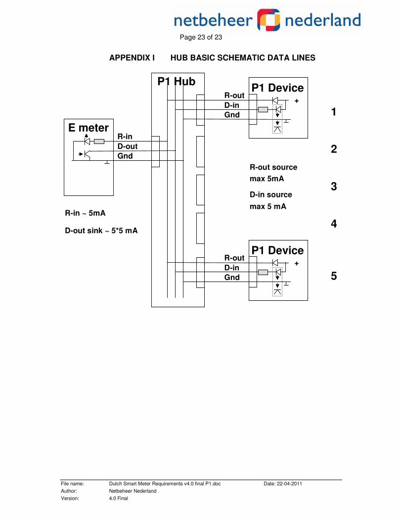
Since a measuring device will have no more than one P1 port, there is no need to address it. The P1 port must be able to handle up to 5 connected P1 devices, and such P1 devices must be able to handle partial messages. The meter has only one P1 port, connecting more
Page 7 of 23
File name: Dutch Smart Meter Requirements v4.0 final P1.doc Date: 22-04-2011 Author: Netbeheer Nederland Version: 4.0 Final
devices will need a hub. The hub is outside the scope of the P1 document, but a basic schematic is shown in Appendix I.
4.5 Measuring device transfer time
The measuring device must complete a data transfer to the P1 device within eight seconds, because the data has to be sent by the P1 port to the P1 device every ten seconds. This means at a minimum there is a pause of two seconds between messages. 4.6 Signals
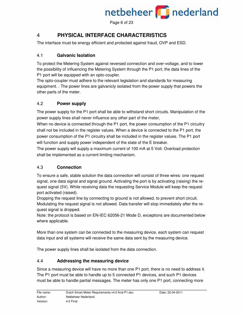
All signals are compliant with following levels (different from the NTA8130!) Operating range per (P1) device as seen from the meter:
Meter OSM Symbol Parameter Min Typ Max Min Typ Max Units
Vi request Request voltage 4 5 5.5 V
Ii request Current supplied to the request pin
4 5 10 mA
Vol data Low level output voltage of the Data pin
1 V
Ii data Input current sinked, supplied by the Data pin per OSM
5 6 mA
Table 4-1: Signal Levels
Limit values: Max Voltage: opto coupler: 15V, driver 6V Max current sink (data output) : max = 30mA Logical levels are specified as follows:
SPACE “0” as > 4V MARK “1” as < 1 V
4.7 Physical connector
The connector type is RJ11. The Metering System holds a female connector, the customer can plug in a standard RJ11 plug. Note that the connector in the metering system is physi-cally accessible at all times and should not be sealed or protected by a sealed cover.
Pin # Signal name Description 1 + 5V Power supply 2 Request Input 3 Data GND Ground
4 N.C. Not Connected 5 Data Output 6 Power GND Power supply
Table 4-2: Physical Connector
Page 8 of 23
File name: Dutch Smart Meter Requirements v4.0 final P1.doc Date: 22-04-2011 Author: Netbeheer Nederland Version: 4.0 Final
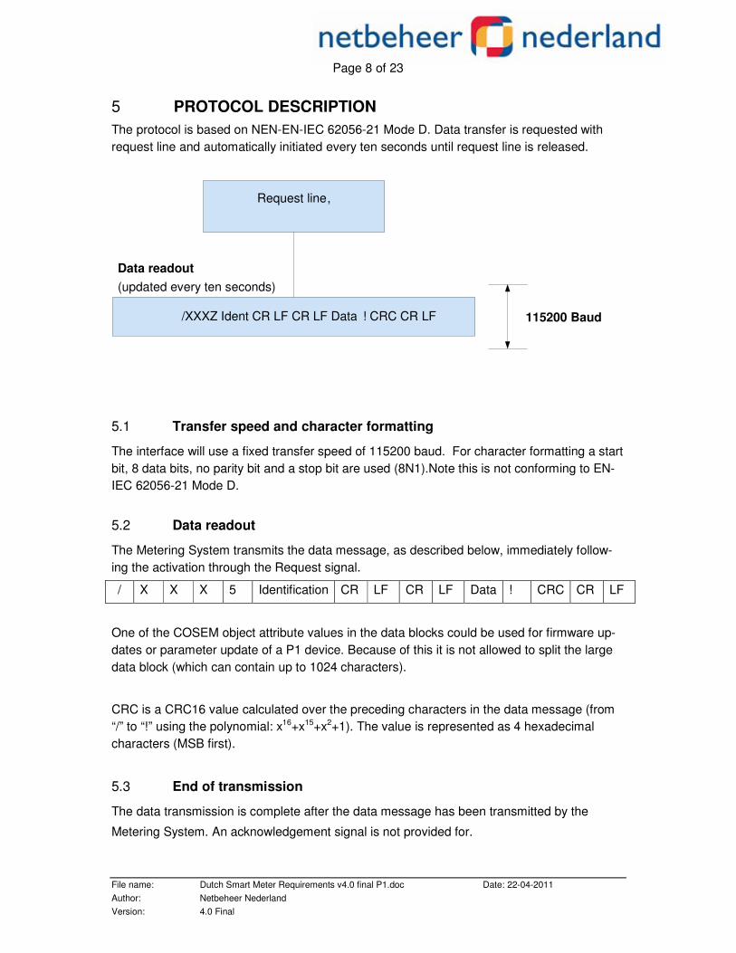
5 PROTOCOL DESCRIPTION The protocol is based on NEN-EN-IEC 62056-21 Mode D. Data transfer is requested with request line and automatically initiated every ten seconds until request line is released.
5.1 Transfer speed and character formatting
The interface will use a fixed transfer speed of 115200 baud. For character formatting a start bit, 8 data bits, no parity bit and a stop bit are used (8N1).Note this is not conforming to EN-IEC 62056-21 Mode D.
5.2 Data readout
The Metering System transmits the data message, as described below, immediately follow-ing the activation through the Request signal.
/ X X X 5 Identification CR LF CR LF Data ! CRC CR LF
One of the COSEM object attribute values in the data blocks could be used for firmware up-dates or parameter update of a P1 device. Because of this it is not allowed to split the large data block (which can contain up to 1024 characters).
CRC is a CRC16 value calculated over the preceding characters in the data message (from “/” to “!” using the polynomial: x16+x15+x2+1). The value is represented as 4 hexadecimal characters (MSB first).
5.3 End of transmission
The data transmission is complete after the data message has been transmitted by the
Metering System. An acknowledgement signal is not provided for.
/ XXXZ Ident CR LF CR LF Data ! CRC CR LF
Request line ,
Data readout (updated every ten seconds)
115200 Baud

Page 9 of 23
File name: Dutch Smart Meter Requirements v4.0 final P1.doc Date: 22-04-2011 Author: Netbeheer Nederland Version: 4.0 Final
5.4 Representation of COSEM objects
IEC 62056-61 [2] specifies the logical names of COSEM objects using OBIS, the Ob-ject Identification System. Value group F is not used. The following Value Formats are used for P1 Data Readout value representations:
Value Format Format/Example Meaning Fn(x,y) F7(3,3) – YYYY.YYY Floating decimal number with a fixed num-
ber of decimals behind the decimal point (in this case 3)
Fn(x,y) F7(0,3) – YYYY.YYY or YYYYY.YY or YYYYYY.Y or YYYYYYY
Floating decimal number with a variable number of decimals behind the decimal point (with a maximum of 3)
In I4 - YYYY Integer number
Sn S6 - CCCCCC Alphanumeric string TST YYMMDDhhmmssX ASCII presentation of Time stamp with
Year, Month, Day, Hour, Minute, Second, and an indication whether DST is active (X=S) or DST is not active (X=W).
Note: n is the number of characters in the string.
Table 5-1: Value Formats
COSEM object attribute values are using the following Value Formats:
COSEM Data Type Tag Value Format null-data 0 Empty
boolean 3 I1
bit-string 4 Sn
double-long 5 Fn(x,y)
double-long-unsigned 6 Fn(x,y)
floating-point 7 Fn(x,y)
octet-string 9 Sn
visible-string 10 Sn
bcd 13 S2
integer 15 In
long 16 Fn(x,y)
unsigned 17 Fn(x,y)
long-unsigned 18 Fn(x,y)
long64 20 Fn(x,y)
long64-unsigned 21 Fn(x,y)
enum 22 In
float-32 23 Fn(x,y), I
float-64 24 Fn(x,y), I
Table 5-2: Cosem Object Attributes
Page 10 of 23
File name: Dutch Smart Meter Requirements v4.0 final P1.doc Date: 22-04-2011 Author: Netbeheer Nederland Version: 4.0 Final
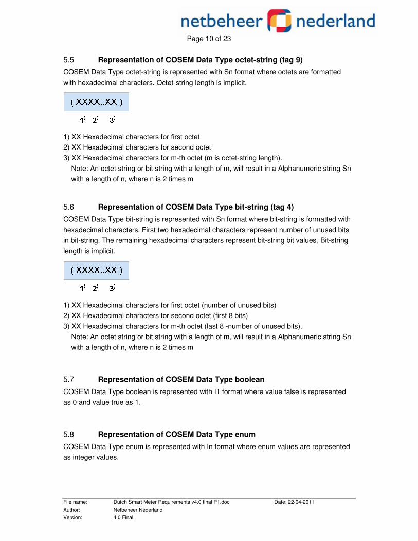
5.5 Representation of COSEM Data Type octet-string (tag 9)
COSEM Data Type octet-string is represented with Sn format where octets are formatted with hexadecimal characters. Octet-string length is implicit.
1) XX Hexadecimal characters for first octet 2) XX Hexadecimal characters for second octet 3) XX Hexadecimal characters for m-th octet (m is octet-string length). Note: An octet string or bit string with a length of m, will result in a Alphanumeric string Sn with a length of n, where n is 2 times m
5.6 Representation of COSEM Data Type bit-string (tag 4)
COSEM Data Type bit-string is represented with Sn format where bit-string is formatted with hexadecimal characters. First two hexadecimal characters represent number of unused bits in bit-string. The remaining hexadecimal characters represent bit-string bit values. Bit-string length is implicit.
1) XX Hexadecimal characters for first octet (number of unused bits) 2) XX Hexadecimal characters for second octet (first 8 bits) 3) XX Hexadecimal characters for m-th octet (last 8 -number of unused bits). Note: An octet string or bit string with a length of m, will result in a Alphanumeric string Sn with a length of n, where n is 2 times m
5.7 Representation of COSEM Data Type boolean
COSEM Data Type boolean is represented with I1 format where value false is represented as 0 and value true as 1.
5.8 Representation of COSEM Data Type enum
COSEM Data Type enum is represented with In format where enum values are represented as integer values.
Page 11 of 23
File name: Dutch Smart Meter Requirements v4.0 final P1.doc Date: 22-04-2011 Author: Netbeheer Nederland Version: 4.0 Final
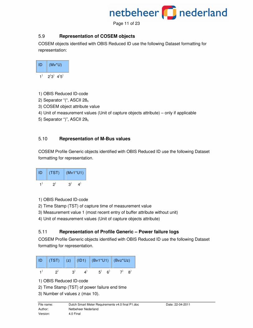
5.9 Representation of COSEM objects
COSEM objects identified with OBIS Reduced ID use the following Dataset formatting for representation:
ID (Mv*U)
1) 2)3) 4)5)
1) OBIS Reduced ID-code 2) Separator “(“, ASCII 28h 3) COSEM object attribute value 4) Unit of measurement values (Unit of capture objects attribute) – only if applicable 5) Separator “)”, ASCII 29h
5.10 Representation of M-Bus values
COSEM Profile Generic objects identified with OBIS Reduced ID use the following Dataset formatting for representation.
ID (TST) (Mv1*U1)
1) 2) 3) 4)
1) OBIS Reduced ID-code 2) Time Stamp (TST) of capture time of measurement value 3) Measurement value 1 (most recent entry of buffer attribute without unit) 4) Unit of measurement values (Unit of capture objects attribute)
5.11 Representation of Profile Generic – Power failure logs
COSEM Profile Generic objects identified with OBIS Reduced ID use the following Dataset formatting for representation.
ID (TST) (z) (ID1) (Bv1*U1) (Bvz*Uz)
1) 2) 3) 4) 5) 6) 7) 8)
1) OBIS Reduced ID-code 2) Time Stamp (TST) of power failure end time 3) Number of values z (max 10).
Page 12 of 23
File name: Dutch Smart Meter Requirements v4.0 final P1.doc Date: 22-04-2011 Author: Netbeheer Nederland Version: 4.0 Final
4) Identifications of buffer values (OBIS Reduced ID codes of capture objects attribute) 5) Buffer value 1 (most recent entry of buffer attribute without unit) 6) Unit of buffer values (Unit of capture objects attribute) 7) Buffer value 2 (oldest entry of buffer attribute without unit) 8) Unit of buffer values (Unit of capture objects attribute)
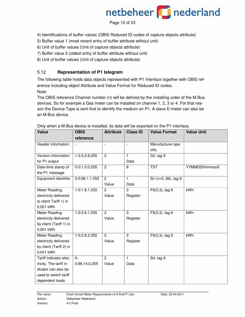
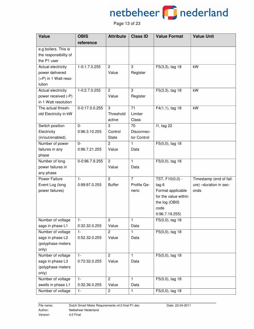
5.12 Representation of P1 telegram
The following table holds data objects represented with P1 Interface together with OBIS ref-erence including object Attribute and Value Format for Reduced ID codes. Note: The OBIS reference Channel number (n) will be defined by the installing order of the M-Bus devices. So for example a Gas meter can be installed on channel 1, 2, 3 or 4. For that rea-son the Device-Type is sent first to identify the medium on P1. A slave E-meter can also be an M-Bus device. Only when a M-Bus device is installed, its data will be exported on the P1 interface. Value OBIS
reference Attribute Class ID Value Format Value Unit
Header information - - - Manufacturer spe-cific
Version information for P1 output
1-3:0.2.8.255 2 1 Data
S2, tag 9
Date-time stamp of the P1 message
0-0:1.0.0.255 2 8 TST YYMMDDhhmmssX
Equipment identifier 0-0:96.1.1.255 2 Value
1 Data
Sn (n=0..96), tag 9
Meter Reading electricity delivered to client Tariff 1) in 0,001 kWh
1-0:1.8.1.255 2 Value
3 Register
F9(3,3), tag 6
kWh
Meter Reading electricity delivered by client (Tariff 1) in 0,001 kWh
1-0:2.8.1.255 2 Value
3 Register
F9(3,3), tag 6
kWh
Meter Reading electricity delivered by client (Tariff 2) in 0,001 kWh
1-0:2.8.2.255 2 Value
3 Register
F9(3,3), tag 6
kWh
Tariff indicator elec-tricity. The tariff in-dicator can also be used to switch tariff dependent loads
0-0:96.14.0.255
2 Value
1 Data
S4, tag 9
Page 13 of 23
File name: Dutch Smart Meter Requirements v4.0 final P1.doc Date: 22-04-2011 Author: Netbeheer Nederland Version: 4.0 Final
Value OBIS reference
Attribute Class ID Value Format Value Unit
e.g boilers. This is the responsibility of the P1 user
Actual electricity power delivered (+P) in 1 Watt reso-lution
1-0:1.7.0.255 2 Value
3 Register
F5(3,3), tag 18 kW
Actual electricity power received (-P) in 1 Watt resolution
1-0:2.7.0.255 2 Value
3 Register
F5(3,3), tag 18 kW
The actual thresh-old Electricity in kW
0-0:17.0.0.255 3 Threshold active
71 Limiter Class
F4(1,1), tag 18 kW
Switch position Electricity (in/out/enabled).
0-0:96.3.10.255
3 Control State
70 Disconnec-tor Control
I1, tag 22
Number of power failures in any phase
0-0:96.7.21.255
2 Value
1 Data
F5(0,0), tag 18
Number of long power failures in any phase
0-0:96.7.9.255 2 Value
1 Data
F5(0,0), tag 18
Power Failure Event Log (long power failures)
1-0:99:97.0.255
2 Buffer
7 Profile Ge-neric
TST, F10(0,0) - tag 6 Format applicable for the value within the log (OBIS code 0:96.7.19.255)
Timestamp (end of fail-ure) –duration in sec-onds
Number of voltage sags in phase L1
1-0:32.32.0.255
2 Value
1 Data
F5(0,0), tag 18
Number of voltage sags in phase L2 (polyphase meters only)
1-0:52.32.0.255
2 Value
1 Data
F5(0,0), tag 18
Number of voltage sags in phase L3 (polyphase meters only)
1-0:72:32.0.255
2 Value
1 Data
F5(0,0), tag 18
Number of voltage swells in phase L1
1-0:32.36.0.255
2 Value
1 Data
F5(0,0), tag 18
Number of voltage 1- 2 1 F5(0,0), tag 18

Page 14 of 23
File name: Dutch Smart Meter Requirements v4.0 final P1.doc Date: 22-04-2011 Author: Netbeheer Nederland Version: 4.0 Final
Value OBIS reference
Attribute Class ID Value Format Value Unit
swells in phase L2 (polyphase meters only)
0:52.36.0.255 Value Data
Number of voltage swells in phase L3 (polyphase meters only)
1-0:72.36.0.255
2 Value
1 Data
F5(0,0), tag 18
Text message co-des: numeric 8 digits
0-0:96.13.1.255
2 Value
1 Data
Sn (n=0..8),, tag 9
Text message max 1024 characters.
0-0:96.13.0.255
2 Value
1 Data
Sn (n=0..2048), tag 9
Device-Type 0-n:24.1.0.255 9 Device type
72 M-Bus cli-ent
F3(0,0), tag 17
Equipment identifier (Gas)
0-n:96.1.0.255 2 Value
1 Data
Sn (n=0..96), tag 9
0-n:24.2.1.255
5 Capture time
4 Extended Register
TST
Last hourly value (temperature con-verted), gas deliv-ered to client in m3, including decimal values and capture time
0-n:24.2.1.255 2 Value
4 Extended Register
F8(2,2)/F8(3,3), tag 18 (See note 2)
m3
Valve position Gas (on/off/released). (See Note 3)
0-n:24.4.0.255 3 Control state
70 Disconnect Control
I1, tag 22
Device-Type 0-n:24.1.0.255 9 Device type
72 M-Bus cli-ent
F3(0,0), tag 17
Equipment identifier (Thermal)
0-n:96.1.0.255 2 Value
1 Data
Sn (n=0..96), tag 9
0-n:24.2.1.255
5 Capture time
4 Extended Register
TST
Last hourly Meter reading Heat in 0,01 GJ and cap-ture time
0-n:24.2.1.255
2 Value
4 Extended Register
Fn(2,2) (See note 1)
GJ
Last hourly Meter reading Cold in 0,01
0-n:24.2.1.255
5 Capture
4 Extended
TST

Page 15 of 23
File name: Dutch Smart Meter Requirements v4.0 final P1.doc Date: 22-04-2011 Author: Netbeheer Nederland Version: 4.0 Final
Value OBIS reference
Attribute Class ID Value Format Value Unit
time
Register
GJ and capture time
0-n:24.2.1.255
2 Value
4 Extended Register
Fn(2,2) (See note 1)
GJ
Valve position (on/off/released). (See Note 3)
0-n:24.4.0.255 3 Control state
70 Disconnect Control
I1, tag 22
Device-Type 0-n:24.1.0.255 9 Device type
72 M-Bus cli-ent
F3(0,0), tag 17
Equipment identifier (Water)
0-n:96.1.0.255 2 Value
1 Data
Sn (n=0..96), tag 9
0-n:24.2.1.255
5 Capture time
4 Extended Register
TST
Last hourly Meter reading in 0,001 m3 and capture time
0-n:24.2.1.255
2 Value
4 Extended Register
Fn(3,3) (See Note 1)
m3
Valve position (on/off/released). (See Note 3)
0-n:24.4.0.255 3 Control state
70 Disconnect Control
I1, tag 22
Device-Type 0-n:24.1.0.255 9 Device type
72 M-Bus cli-ent
F3(0,0), tag 17
Equipment identifier 0-n:96.1.0.255 2 Value
1 Data
Sn (n=0..96), tag 9
0-n:24.2.1.255
5 Capture time
4 Extended Register
TST
Last hourly Meter reading and capture time (e.g. slave E meter)
0-n:24.2.1.255
2 Value
4 Extended Register
Fn(3,3) (See Note 1)
kWh
Valve/Switch posi-tion (on/off/released). (See Note 3)
0-n:24.4.0.255 3 Control state
70 Disconnect Control
I1, tag 22
Table 5-3: P1 Telegram Representation
Note 1: Where n is the number of digits before the decimal point on the display of the meter + the required number of decimals. So for example if on the physical display of a Heat meter is
Page 16 of 23
File name: Dutch Smart Meter Requirements v4.0 final P1.doc Date: 22-04-2011 Author: Netbeheer Nederland Version: 4.0 Final
shown 1234 GJ (without decimals) the n=6 and the format of the P1 output will be 1234,56 GJ.
Note 2: For Gas meters with a capacity up to 10 m3/h (G4 and G6) F8(3,3) is applicable. For Gas meters with higher capacities F8(2,2) is applicable.
Note 3: Valve position only applicable when present.
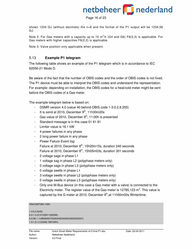
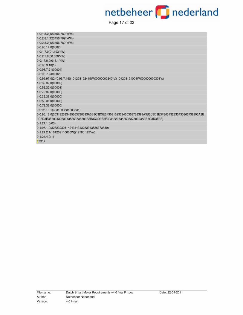
5.13 Example P1 telegram
The following table shows an example of the P1 telegram which is in accordance to IEC 62056-21 Mode D. Be aware of the fact that the number of OBIS codes and the order of OBIS codes is not fixed. The P1 device must be able to interpret the OBIS codes and understand the representation. For example: depending on installation, the OBIS codes for a heat/cold meter might be sent before the OBIS codes of a Gas meter. The example telegram below is based on:
- DSMR version 4.0 (value 40 behind OBIS code 1-3:0.2.8.255) - It is send at 2010, December 9th, 11h30m20s - Gas value of 2010, December 9th, 11:00h is presented - Standard message is in this case 01 61 81 - Limiter value is 16.1 kW - 4 power failures in any phase - 2 long power failure in any phase - Power Failure Event log:
Failure at 2010, December 8th, 15h20m15s, duration 240 seconds Failure at 2010, December 8th, 15h05m03s, duration 301 seconds
- 2 voltage sags in phase L1 - 1 voltage sag in phase L2 (polyphase meters only) - 0 voltage sags in phase L3 (polyphase meters only) - 0 voltage swells in phase L1 - 3 voltage swells in phase L2 (polyphase meters only) - 0 voltage swells in phase L3 (polyphase meters only) - Only one M-Bus device (in this case a Gas meter with a valve) is connected to the
Electricity meter. The register value of the Gas meter is 12785,123 m3. This value is captured by the G meter at 2010, December 9th,at 11h00m00s Wintertime.
/ISk5\2MT382-1000
1-3:0.2.8(40) 0-0:1.0.0(101209113020W) 0-0:96.1.1(4B384547303034303436333935353037) 1-0:1.8.1(123456.789*kWh)
Page 17 of 23
File name: Dutch Smart Meter Requirements v4.0 final P1.doc Date: 22-04-2011 Author: Netbeheer Nederland Version: 4.0 Final
1-0:1.8.2(123456.789*kWh) 1-0:2.8.1(123456.789*kWh) 1-0:2.8.2(123456.789*kWh) 0-0:96.14.0(0002) 1-0:1.7.0(01.193*kW) 1-0:2.7.0(00.000*kW) 0-0:17.0.0(016.1*kW) 0-0:96.3.10(1) 0-0:96.7.21(00004) 0-0:96.7.9(00002) 1-0:99:97.0(2)(0:96.7.19)(101208152415W)(0000000240*s)(101208151004W)(00000000301*s) 1-0:32.32.0(00002) 1-0:52.32.0(00001) 1-0:72:32.0(00000) 1-0:32.36.0(00000) 1-0:52.36.0(00003) 1-0:72.36.0(00000) 0-0:96.13.1(3031203631203831) 0-0:96.13.0(303132333435363738393A3B3C3D3E3F303132333435363738393A3B3C3D3E3F303132333435363738393A3B 3C3D3E3F303132333435363738393A3B3C3D3E3F303132333435363738393A3B3C3D3E3F) 0-1:24.1.0(03) 0-1:96.1.0(3232323241424344313233343536373839) 0-1:24.2.1(101209110000W)(12785.123*m3) 0-1:24.4.0(1) !522B

Page 18 of 23
File name: Dutch Smart Meter Requirements v4.0 final P1.doc Date: 22-04-2011 Author: Netbeheer Nederland Version: 4.0 Final
6 DATA OBJECTS Data Objects are defined in NEN-EN-IEC 62056-61:2002 Electricity metering – Data exchange for meter reading, tariff and load control – Part 61: OBIS Object Identification System. The following tables hold data objects and references to the OBIS. Note that this table assumes two tariffs. Currently two tariffs (Rate 1 low tariff and Rate 2 normal/high tariff) are defined, support for up to sixteen tariffs should be included. 6.1 Electricity data
Electricity –P1 transfers every ten seconds Value OBIS reference NTA Use Case reference Equipment identifier 0-0:96.1.1.255 Use case 3: Provide actual
meter reads through P1 Use case 5: Provide equip-ment status to P1
Meter Reading electricity delivered to client (low tariff) in 0,001 kWh
1-0:1.8.1.255
Use case 3: Provide actual meter reads through P1
Meter Reading electricity delivered to client (normal tariff) in 0,001 kWh
1-0:1.8.2.255 Use case 3: Provide actual meter reads through P1
Meter Reading electricity delivered by client (low tariff) in 0,001 kWh
1-0:2.8.1.255 Use case 3: Provide actual meter reads through P1
Meter Reading electricity delivered by client (normal tariff) in 0,001 kWh
1-0:2.8.2.255 Use case 3: Provide actual meter reads through P1
Tariff indicator electricity. The tariff indicator can be used to switch tariff dependent loads e.g boilers. This is responsibility of the P1 user
0-0:96.14.0.255 Use case 5: Provide equip-ment status to P1
Actual electricity power delivered (+P) in 1 Watt resolution
1-0:1.7.0.255 Use case 3: Provide actual meter reads through P1
Actual electricity power received (-P) in 1 Watt resolution
1-0:2.7.0.255 Use case 3: Provide actual meter reads through P1
The actual threshold Electricity in kW
0-0:17.0.0.255 Use case 5: Provide equip-ment status to P1
Switch position Electricity (in/out/enabled).
0-0:96.3.10.255 Use case 5: Provide equip-ment status to P1
Number of power failures in any phases
0-0:96.7.21.255 Use case 7: Provide power quality information to P1
Number of long power failures in any phases
0-0:96.7. 9.255 Use case 7: Provide power quality information to P1
Power failure event log 1-0:99:97.0.255 Use case 7: Provide power

Page 19 of 23
File name: Dutch Smart Meter Requirements v4.0 final P1.doc Date: 22-04-2011 Author: Netbeheer Nederland Version: 4.0 Final
Value OBIS reference NTA Use Case reference quality information to P1
Number of voltage sags in phase L1 1-0:32.32.0.255 Use case 7: Provide power quality information to P1
Number of voltage sags in phase L2 (polyphase meters only)
1-0:52.32.0.255 Use case 7: Provide power quality information to P1
Number of voltage sags in phase L2 (polyphase meters only)
1-0:72.32.0.255 Use case 7: Provide power quality information to P1
Number of voltage swells in phase L1
1-0:32.36.0.255 Use case 7: Provide power quality information to P1
Number of voltage swells in phase L2 (polyphase meters only)
1-0:52.36.0.255 Use case 7: Provide power quality information to P1
Number of voltage swells in phase L3 (polyphase meters only)
1-0:72.36.0.255 Use case 7: Provide power quality information to P1
Note: Tariff code 1 is used for low tariff and tariff code 2 is used for normal tariff.
6.2 Messages Text messages, transfer every ten seconds Value OBIS reference NTA Use Case reference Text message codes: numeric 8 digits
0-0:96.13.1.255 Use case 12: Display stan-dard messages on meter display and P1
Text message max 1024 charac-ters.
0-0:96.13.0.255 Use case 13: Sending long messages to port P1
The Meter will have storage capacity for one numeric message code (up to 8 numeric char-acters) and one 1024 character text message. Message codes and text messages are han-dled independently, but in the same way. An example of a standard message code is: 01. This means that the electricity is discon-nected by the grid operator. Another example of a standard message code is 01 61 81. This standard message consists out of the maximum of 8 characters. The standard message codes can be found in the document describing the P4 port (see the document list) If a device is connected, the meter will send the message (code and/or text) over the P1 in-terface every ten seconds. The text message can not be extended with CR,LF (0A,0Dh) to split the message

Page 20 of 23
File name: Dutch Smart Meter Requirements v4.0 final P1.doc Date: 22-04-2011 Author: Netbeheer Nederland Version: 4.0 Final
6.3 Gas Data
The following is only applicable if Gas meters are connected. The OBIS reference Channel number (n) will be defined by the installing order of the M-Bus devices. So a Gas meter can be installed on channel 1, 2, 3 or 4. Gas – P1 transfers every ten seconds the latest received hourly value & timestamp Value OBIS reference NTA Use Case reference Device-Type 0-n:24.1.0.255 Equipment identifier 0-n:96.1.0.255 Use case 3: Provide actual
meter reads through P1 Last hourly value (temperature con-verted), gas delivered to client in m3, including decimal values and capture time
0-n:24.2.1.255 Use case 3: Provide actual meter reads through P1
Valve position gas (on/off/released). (see note 1)
0-n:24.4.0.255 Use case 5: Provide equip-ment status to P1
Note 1: Valve position only applicable when present.
6.4 Thermal Data
The following is only applicable if Thermal (H/C) meters are connected. The OBIS reference Channel number (n) will be defined by the installing order of the M-Bus devices. So a Ther-mal meter can be installed on channel 1, 2, 3 or 4. Thermal (H/C)– P1 transfers every ten seconds the latest received hourly value & timestamp Value OBIS reference NTA Use Case reference Device-Type 0-n:24.1.0.255 Equipment identifier 0-n:96.1.0.255 Use case 3: Provide actual
meter reads through P1 (x=5:Heat; x=6: Cooling)
Last hourly Meter reading Heat/Cold in 0,01 GJ and capture time
0-n:24.2.1.255 Use case 3: Provide actual meter reads through P1
Valve position Thermal (on/off/released). (See note 1)
0-n:24.4.0.255 Use case 5: Provide equip-ment status to P1
Note 1: Valve position only applicable when present.
6.5 Water Data
The following is only applicable if water meters are connected. The OBIS reference Channel number (n) will be defined by the installing order of the M-Bus devices. So a water meter can be installed on channel 1, 2, 3 or 4.

Page 21 of 23
File name: Dutch Smart Meter Requirements v4.0 final P1.doc Date: 22-04-2011 Author: Netbeheer Nederland Version: 4.0 Final
Water –P1 transfers every ten seconds the latest received hourly value & timestamp Value OBIS reference NTA Use Case reference Device-Type 0-n:24.1.0.255 Equipment identifier 0-n:96.1.0.255 Use case 3: Provide ac-
tual meter reads through P1
Last hourly Meter reading in 0,001 m3 and capture time
0-n:24.2.1.255 Use case 3: Provide ac-tual meter reads through P1
Valve position Water (on/off/released). (See note 1)
0-n:24.4.0.255 Use case 5: Provide equipment status to P1
Note 1: Valve position only applicable when present.
6.6 M-Bus Data of a fourth M-Bus device (for example a slave E-meter to measure electricity production)
The following is only applicable if a fourth M-Bus device is connected. The OBIS reference Channel number (n) will be defined by the installing order of the M-Bus devices. So the fourth M-Bus device can be installed on channel 1, 2, 3 or 4. Fourth M-Bus device –P1 transfers every ten seconds the latest received hourly value & time-stamp Value OBIS reference NTA Use Case reference Device-Type 4th M-Bus device 0-n:24.1.0.255 Equipment identifier 0-n:96.1.0.255 Use case 3: Provide ac-
tual meter reads through P1
Last hourly Meter reading and cap-ture time
0-n:24.2.1.255 Use case 3: Provide ac-tual meter reads through P1
If applicable, Valve/Switch position (on/off/released). (See note 1)
0-n:24.4.0.255 Use case 5: Provide equipment status to P1
Note 1: Valve/Switch position only applicable when present.
6.7 Change of M-Bus device
If an M-Bus device is exchanged by another device type, the OBIS codes on P1 have to be changed accordingly.
Page 22 of 23
File name: Dutch Smart Meter Requirements v4.0 final P1.doc Date: 22-04-2011 Author: Netbeheer Nederland Version: 4.0 Final
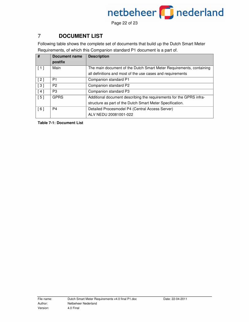
7 DOCUMENT LIST Following table shows the complete set of documents that build up the Dutch Smart Meter Requirements, of which this Companion standard P1 document is a part of. # Document name
postfix Description
[ 1 ] Main
The main document of the Dutch Smart Meter Requirements, containing all definitions and most of the use cases and requirements
[ 2 ] P1 Companion standard P1
[ 3 ] P2 Companion standard P2
[ 4 ] P3 Companion standard P3 [ 5 ] GPRS Additional document describing the requirements for the GPRS infra-
structure as part of the Dutch Smart Meter Specification.
[ 6 ] P4 Detailed Procesmodel P4 (Central Access Server) ALV NEDU 20081001-022
Table 7-1: Document List
Page 23 of 23
File name: Dutch Smart Meter Requirements v4.0 final P1.doc Date: 22-04-2011 Author: Netbeheer Nederland Version: 4.0 Final
APPENDIX I HUB BASIC SCHEMATIC DATA LINES
E meter D-out R-in
Gnd
P1 Hub
D-in R-out
Gnd
+ P1 Device
D-in R-out
Gnd
+ P1 Device
1
5
2
3
4 D-out sink ~ 5*5 mA
R-in ~ 5mA
D-in source max 5 mA
R-out source max 5mA