P. David Romei Arts Center - Faculty...
15
2275 D 2275 D artmouth artmouth Avenue venue Arts Center Arts Center College Station College Station, T , T exas exas P. David P. David Romei Romei
Transcript of P. David Romei Arts Center - Faculty...
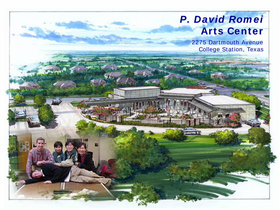
2275 D2275 Dartmouthartmouth AAvenuevenue
Arts CenterArts Center
College StationCollege Station, T, Texasexas
P. David P. David RomeiRomei

Owner : Arts Council of Brazos Valley
Architect : Jim Singleton Architects
Structure : Robertson Consulting Engineers
Political / Funding BackgroundThe P.David Romei Arts Center is a public building funded through donations and w+
ith a portion of the Brazos County hotel tax. The center is home to over 40 local artist groups, including the Brazos Valley Veterans Memorial, the Brazos Valley Art League, the quilter’s guild and many more.
Programming & FunctionThe 5500 square foot building houses administrative offices, a retail space, classroom space, and a gallery for display. The city was constructed on public land in the Wolf Pen Creek Parks and Recreation District. It overlooks the Wolf Pen Creek amphitheater. The site will also be home for a permanent sculpture by Russian artist Dmitri Koustov.

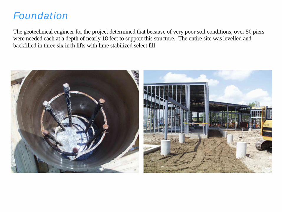
FoundationThe geotechnical engineer for the project determined that because of very poor soil conditions, over 50 piers were needed each at a depth of nearly 18 feet to support this structure. The entire site was levelled and backfilled in three six inch lifts with lime stabilized select fill.

Design Loads
1. The foundation has been designed according to the requirements
of the International Building Code.
Design Wind Speed = 90 mph.
Earthquake Zone 0
2. The foundation has been designed for the following live loads:
Roof = 20 psf
Floor Slabs on Grade = 500 psf
Suspended Floor Slabs = 100 psf
3. Drilled footing design is based upon an allowable bearing pressure
of 7500 psf for dead loads and 11,250 psf for dead plus live load.

MECHANICAL SYSTEM
WIND UPLIFT
DEAD LOADLATERAL FORCEREACTION FORCE


Structural Steel

Structural Steel
1. Design, fabrication, and erection of structural steel shall
be in accordance with AISC Specifications, latest editio
n. All cold rolled structural shapes shall meet the requi
rements of the AISI, latest edition.
2. All structural shapes and plates shall conform to ASTM
A36-81a. Structural tubing shall conform to ASTM A5
01 and have a minimum yield point of 46 KSI. Structur
al pipe shall conform to ASTM A53.
3. Unless shown otherwise, connections shall be shop welde
d and field bolted and shall be in accordance with the st
andards of the AISC. Bolts, including anchor bolts, shal
l be ASTM A307 or ASTM A325 as required by the spec
ific connection detail.
4. Splicing of structural steel members is prohibited witho
ut prior review by the structural engineer as to type and
location of splice. Splices shall be detailed on the shop d
rawings.
5. Burning and/or torch cutting of holes in members is expre
ssly prohibited.
6. All welds shall be made with A-233 Class E-70 Series electrode or by
submerged arc welding S.A.W. 2 in accordance with the Structural Welding
Code AWS D1.1-96.
7. All structural steel shall be shop painted with a rust inhibiting primer
to a 2 mil dry film thickness. Exclude paint from areas within 2 inches
of field welded connections. Field touch-up painting shall be accomplished
on those areas when welding operations are complete.
8. Provide temporary bracing for accurate plumbing, and to resist all wind
and construction loads. Contractor shall maintain temporary bracing until
all permanent lateral bracing (including diagonal bracing, moment
connections, and/or walls) are installed and approved.
9. All openings through roof and floor decks are shown. Ope nings of 6" or
less require no additional framing. Openings larger than 6" shall be
framed with the typical size finish edge angle or as shown on Drawings.
Additional openings shall be with the Architect's approval.

Steel Joists and Joist Girders1. All steel joists and joist girders shall conform to specifications of the Steel Joist Institute, applicable
series. Top chords shall be angles or tee sections. Bridging shall be rigid cross-type or horizontal type
as indicated on the drawings. Bridging shall be continuous and terminate at masonry walls, concrete
walls or steel beams.
2. Unless otherwise shown, weld all joists to steel bearing seats with 1/8“ fillet welds, one inch long on
each side of the seats.
3. SPECIAL JOIST DESIGN LOADS: The joists supporting the parking deck shall be designed for 150
psf DL + LL uniform load; or 50 psf DL uniform load and 2 - 2000 lb concentrated loads spaced 5' apart
placed at any location along the span of the joists.

Finish

Interior