P-CABLE ULTRAHIGH RESOLUTION (UHR) MARINE SEISMIC
12
Ultrahigh Resolution Seismic. A Marine Seismic Company
Transcript of P-CABLE ULTRAHIGH RESOLUTION (UHR) MARINE SEISMIC

Ultrahigh Resolution
Seismic.
A Marine Seismic Company

-
j J
-,__-.. 1 ~
When Resolution Matters R E A L T I M E C O V E R AG E
A Marine Seismic Company

NCSla::::J SubSea 5 Cable
P-C ABLE ULTRAHIGH RESOLUTION (UHR) M ARINE SEISMIC
NCS SubSea and P-Cable 3D Seismic have pioneered the commercial development of the P-Cable ultrahigh resolution recording system as an unrivaled tool for providing extremely detailed images of geology at and beneath the seafloor.
Using proprietary navigation and seismic acquisition technologies to augment the accuracy, robustness, and reliability of this system over the past several years, we have been able to produce subsurface images of astounding quality and fidelity.
Aerial view of a P-Cable ultrahigh resolution marine acquisition system in operation. For this survey, NCS SubSea deployed an 18 x 100 meter streamer spread with dual airgun source arrays to record 4 fold data in 3.125 x 3.125 meter bins at a 0.25 millisecond temporal sampling interval.
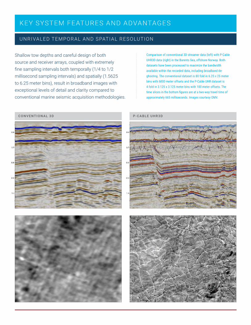
UNRIVALED TEMPORAL AND SPATI AL RESOLUTION
KEY SYSTEM FEATURES AND ADVANTAGES
Shallow tow depths and careful design of both source and receiver arrays, coupled with extremely fine sampling intervals both temporally (1/4 to 1/2 millisecond sampling intervals) and spatially (1.5625 to 6.25 meter bins), result in broadband images with exceptional levels of detail and clarity compared to conventional marine seismic acquisition methodologies.
C O N V E NT I O N A L 3 D
Comparison of conventional 3D streamer data (left) with P-Cable UHR3D data (right) in the Barents Sea, offshore Norway. Both datasets have been processed to maximize the bandwidth available within the recorded data, including broadband de-ghosting. The conventional dataset is 80 fold in 6.25 x 25 meter bins with 6000 meter offsets and the P-Cable UHR dataset is 4 fold in 3.125 x 3.125 meter bins with 100 meter offsets. The time slices in the bottom figures are at a two-way travel time of approximately 665 milliseconds. Images courtesy OMV.
P-C A B L E U H R 3 D
VI Cl>
50
40
~ 30
i=
20
10
0
0
P-Cable Offset Distribution
Outer
Central
50 100 150 200 250 300 350
NCSl§:l SubSea 5 Cable
Conventional Offset Distribution
400 450 500 550 600 650 700 750 800 850 900
Offset [m]
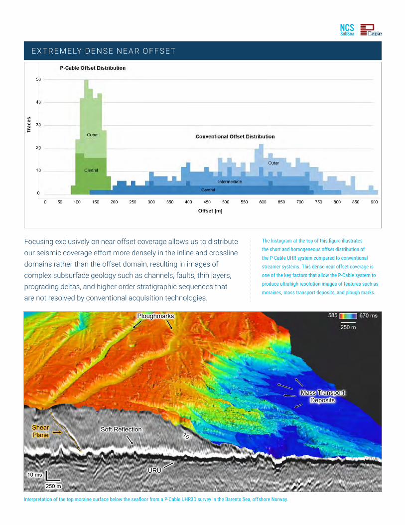
EXTREMELY DENSE NEAR OFFSE T
Focusing exclusively on near offset coverage allows us to distribute our seismic coverage effort more densely in the inline and crossline domains rather than the offset domain, resulting in images of complex subsurface geology such as channels, faults, thin layers, prograding deltas, and higher order stratigraphic sequences that are not resolved by conventional acquisition technologies.
The histogram at the top of this figure illustrates the short and homogeneous offset distribution of the P-Cable UHR system compared to conventional streamer systems. This dense near offset coverage is one of the key factors that allow the P-Cable system to produce ultrahigh resolution images of features such as moraines, mass transport deposits, and plough marks.
Interpretation of the top moraine surface below the seafloor from a P-Cable UHR3D survey in the Barents Sea, offshore Norway.

C OMPA CT AND C ONFIGURABLE
The relatively small amount of equipment and streamers, along with the use of fewer winches/reels than conventional seismic, means that it is feasible to air freight equipment to the job site and install it on a vessel of opportunity. Our ability to design the streamer spacing and receiver group interval to meet specific geophysical and geologic objectives means that we can field a source and receiver spread that is tailored to your specific application.
P-C A B L E X R S O L I D S T R E A M E R
S T R E A M E R S I Z E C O M PA R I S O N
Conventional 6km Streamer
P-Cable
The P-Cable system has been deployed in a wide variety of configurations depending on the specific application. The vessels utilized to field the system have ranged from small geotechnical or platform supply vessels up to conventional low capacity seismic vessels. Even for the largest P-Cable spreads, the total active equipment complement is less than 2 kilometers of streamer.

NCSILl SubSea 5 Cable
Abo¥• ·~20e1a·. "~ 60 Ail
Frequtney Ht
200 300
Above '-20dB' • 0-13D Hr!
'll
F uent- Hz
100 200 300
EXPLORATION AND APPRAISAL
APPLIC ATIONS
The initial identification and evaluation of hydrocarbon prospects is predominantly based on seismic data. In the exploration process, seismic resolution is of high importance for delineating and interpreting direct hydrocarbon indicators and the predicted reservoir intervals, precisely defining the closures and the seal integrity of the petroleum system.
P-Cable UHR3D seismic has been used in several exploration licensing rounds on the Norwegian continental shelf. By revealing 3D features below the resolution of conventional data, it became an important contributor for the understanding of the Jurassic reservoir interval in undrilled areas on the Bjarmeland Platform. Furthermore, the data have allowed for detailed mapping of fluid contacts in thin reservoirs and evaluation of the seal integrity.
S E I S M I C D ATA ZO O M I N A M P L IT U D E S P E CT R A

"' E 0 0 N
A
1500m
Hi-Res Conventional 3D P-Cable UHR3D
--~ =
GEOH AZ ARD
H I-R E S C O N V E NT I O N A L 3 D P-C A B L E U H R 3 D
Comparison of reprocessed legacy 3D streamer data (left) with P-Cable UHR3D data (right) in the US Gulf of Mexico. The ultrahigh resolution P-Cable data resolves features such as gas chimneys and mass transport deposits with an unprecedented level of detail and clarity. Images courtesy BP; Hill, et. al., The Leading Edge Geohazards: April 2015.
P-Cable UHR3D seismic data offers unrivaled imaging of subsurface hazards for drilling and infrastructure safety and represents a step change in geohazard evaluation. Broadband 3D imaging of the subsurface ensures the accurate delineation of subsurface hazards from water-bottom down to a kilometer or more below seabed with unprecedented resolution and image quality.
P-C A B L E U H R 3 D D ATA S P E C I F I C A L LY P R O V I D E S A N U N R I VA L E D A B I L IT Y TO I M AG E:
Seafloor bathymetry at a level of detail comparable to shipborne multibeam echo sounder data
Small scale faults and diffractors, including steeply dipping fault planes
Extremely detailed seismo-stratigraphic information from the seabed to at least 1000 meters below seabed, including thin beds and pinch outs
Free gas in the subsurface, including gas chimneys, gas clouds, trapped free gas, and active gas expulsion features
Gas hydrates, both indirectly using free gas underneath the hydrates (BSR’s), and possibly directly in favorable circumstances using detailed amplitude analysis

NCS I a:::1 SubSea 55 Cable
FIELD DEVELOPMENT
W E L L LO G C O N V E NT I O N A L P-C A B L E A 300 km2 P-Cable field development survey was acquired on the Wisting license in 2016. The data represented a leap in both vertical and horizontal resolution and resolved features of the reservoir not imaged before. In turn, this was an important contributing factor for the increase in the reserve estimates. Initial studies of the P-Cable data increased the reserve estimate by more than 30% to 330 boe. After detailed studies, the reserve estimate was again increased in early 2019 to 440 boe. Images courtesy OMV and VBPR.
Detailed knowledge of reservoir properties is key for a successful field development. UHR3D seismic allows for delineation of thin beds; imaging of smaller scale faulting; improved visualization of fluid contacts and spill points; leakage and seal integrity analysis. The uplift in resolution can also be important for imaging small features contributing to the interpretation depositional environment and estimating net to gross. The near zero offset data allows for a precise well to seismic tie. P-Cable UHR3D provides the resolution you need for better estimates of volumes in place and tools for placing wells for production.

4D RESERVOIR MONITORING
4D reservoir monitoring demands a high level of positional repeatability over the course of time lapse surveys, a characteristic that may preclude conventional streamer data acquisition as a candidate due to variations in streamer feathering between surveys. Due to its compact size, even though a P-Cable receiver spread is subject to the same variations as a result of currents, these variations do not significantly impact source and receiver repeatability given the short offsets involved. Experience has shown the P-Cable surveys have repeatability comparable to traditional OBN surveys at a fraction of the cost. Where 4D signals are expected to be present in zero offset data, either as a change in zero offset amplitude or as a time shift – time lapse P-Cable surveys can be a financially attractive alternative for reservoir monitoring and management.
O B N D ATA P-C A B L E D ATA
A comparison of 200 fold OBN data with 6000 meter offsets (left) and 4 fold P-Cable data with 100 meter offsets (right). Although the two datasets have comparable trace densities, the P-Cable data are distributed in the inline and crossline dimensions rather than the offset dimension, thereby supporting enhanced resolution in the shallow overburden shown in the lower image. Images courtesy Shell International.

Reduce Risk, Reveal Opportunity
AC O U S T I C I M P E D A N C E I N V E R S I O N
Acoustic impedance inversion of P-Cable UHR3D data from the Wisting Field with gamma ray log for the Hansen well overlain. Note the unprecedented resolution of the P-Cable inversion, which clearly highlights all three fluid phases along the target formation. Image courtesy OMV.
A Marine Seismic Company
A Marine Seismic Company
NCS SUBSEA INC HOUSTON OFFICE
3928 Bluebonnet Drive Stafford, Texas 77477
P: 281.491.3123 F: 281.491.3105
www.ncs-subsea.com [email protected] www.pcable.com