Ozone technical paper
24
Knowledge Paper No.3 Ozone - technical aspects of its generation and use By Peter I.L. Rüütel, John Griffiths, Feng Xiong and Peter Barratt This paper is published to encourage the sharing and transfer of knowledge
Transcript of Ozone technical paper

Knowledge Paper No.3
Ozone - technical aspects of its generation and useBy Peter I.L. Rüütel, John Griffiths, Feng Xiong and Peter Barratt
This paper is published to encourage the sharing and transfer of knowledge


Knowledge Paper No.3
Ozone – technical aspects of its generation and useBy Peter I.L. Rüütel, John Griffiths, Feng Xiong and Peter Barratt

Ozone has been produced on a commercial scale for over 100 years and is finding more and more acceptance in industrial water treatment. Yet Ozone’s use as an oxidant and its generation from oxygen is not widely known in the waste water treatment industry. This knowledge paper aims to provide an introduction to ozone generation methods and equipment, and outline the key design considerations for a commercial ozone generation plant.
All rights reserved. No part of this publication may be reproduced without the prior permission of Air Products.
Every effort has been made to ensure the information contained in this publication is correct at the time of going to press. No responsibility can be accepted by Air Products or the authors for action taken as a result of information contained in this publication.

Clockwise from top left:
Peter Rüütel specialises in Ozone technology and processes. With a M.Eng in Chemical Engineering from Surrey University he has spearheaded the Air Products Ozone offering. To date he has co-authored five papers on ozone.
John Griffiths is involved in process plant development and integration. With a M.Eng in Chemical Engineering from Imperial College, he has a broad experience in international process engineering support.
Feng Xiong has been at the edge of ozone science and engineering for over 12 years with training from one of the best ozone schools, University of Poitiers in France. He has published a number of peer reviewed papers and patents in relation to ozone chemistry and applications.
Peter Barratt leads a development and implementation team providing specialised oxidation technology for the treatment of industrial waste water. With a PhD in Environmental Chemistry and Biochemistry, he has more than 10 years experience in effluent treatment.

What is Ozone?Ozone, the tri-atomic form of oxygen, is an unstable gas which readily decomposes to oxygen. Many people associate ozone with the ozone layer in the stratosphere – the layer which filters out ultraviolet radiation – or as a pollutant component of smog. Ozone’s use as an environmentally friendly oxidant and disinfectant in numerous processes ranging from drinking water disinfection through the bleaching of paper to the oxidation of harmful components in waste water is not widely known.
The odour of ozone in the vicinity of an electrical machine was first noted by van Marum in 1785 but it was not until 1840 that ozone was discovered by the German scientist Christian Schönbein. He derived the name from the greek word “ozein” which means “to smell” – thanks to ozone’s pungent, characteristic odour at low concentrations. It was not until 1886 that de Meritens recognised ozone’s ability to disinfect polluted water. It took another seven years before the first commercial scale ozone system for the disinfection of drinking water was installed at Oudshoorn in the Netherlands. This was shortly followed by an installation in Paris (1898) and two in Germany (1901/2). The number of installations grew rapidly until 1914.
The rapid growth in the use of ozone slowed dramatically after the first world war when, as a result of research on poisonous gases, chlorine became inexpensive to produce and was favoured as a disinfectant. Despite this the use of ozone continued to grow gradually as it was realised that ozone not only disinfected but improved the taste and odour of drinking water. The 1960’s saw a revival of ozone and the introduction of several new applications mainly in the area of water pre-treatment and colour removal.
More recently, mainly as a result of stricter environmental legislation, ozone has begun to play a major part in production processes such as chemical synthesis, paper manufacture and waste water treatment.

Ozone - technical aspects of its generation and useOzone is one of the most powerful oxidants available. This together with its tendency to decompose to oxygen makes it ideal for use in water and waste water treatment processes.
Ozone is formed naturally in the environment; in the stratosphere it is produced photochemically as a result of UV radiation, and at ground level ozone is generated by the electrical discharges associated with lightning and through chemical interactions between sunlight, air and pollutants in smog. Commercial production of ozone is traditionally achieved by electrically exciting oxygen either in air or pure oxygen at the point of use. This process requires energy and produces heat making ozone a relatively costly gas. The key to a cost effective process is therefore the efficient production, dissolution and reaction of ozone, the key criteria for which are outlined below.
The Properties of Ozone
Ozone (O3) is a chemically unstable, toxic, blue gas with a characteristically pungent odour. Ozone concentrations as low as 0.5ppm (mg O3/l) can cause pulmonary oedema (lung disorders) and a 30 minute exposure to a concentration of 50ppm may cause death1. This makes monitoring of the ambient air an essential safety feature for a commercial plant, especially as 0.01ppm is the threshold of odour perception. The characteristic blue colour of gaseous ozone is not noticeable unless the gas is viewed through a considerable depth.
Ozone decomposition at room temperature depends mainly on surface or chemical reactions. In ambient air the half life is around 30min but a half life of up to 100 hours can be expected in very clean glass vessels. At elevated temperatures (350°C) the half life is reduced to a fraction of a second, hence the use of thermal destructors in the downstream stage of commercial processes. Many solids will catalyse the decomposition of ozone and so are also found as destructors in commercial processes.
Ozone Reaction ChemistryIn aqueous solutions, ozone reacts with compounds via two principal mechanisms2,3:
• direct reaction with the ozone molecule• indirect reaction through radicals formed when ozone decomposes
Direct reaction
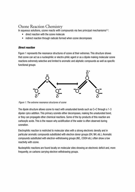
Figure 1 represents the resonance structures of ozone at their extremes. This structure shows that ozone can act as a nucleophilic or electro-philic agent or as a dipole making molecular ozone reactions extremely selective and limited to aromatic and aliphatic compounds as well as specific functional groups
The dipole structure allows ozone to react with unsaturated bonds such as C=C through a 1-3 dipolar cylco addition. This primary ozonide either decomposes, reaking the unsaturated bond, or they can propagate other chemical reactions. Some of the by-products of this reaction are carboxylic acids. This is the reason why acidification of the water is often observed during ozonation.
Electrophilic reaction is restricted to molecular sites with a strong electronic density and in particular aromatic compounds substituted with electron donor groups (OH, NH2 etc.). Aromatic compounds substituted with electron-withdrawing groups (NO2, COOH etc.) often show a low reactivity with ozone.
Nucleophilic reactions are found locally on molecular sites showing an electronic deficit and, more frequently, on carbons carrying electron withdrawing groups.
O O
O OOO
••δ+
δ-••••••••
••
••
••
••••••••
••
δ-δ+
Figure 1: The extreme resonance structures of ozone

Indirect Reaction
Indirect reaction processes rely on the formation of radicals from ozone. These processes are often given the name Advanced Oxidation Processes (AOP). They are typified through the use of hydrogen peroxide, ultraviolet light or catalysts to induce the decomposition of ozone to generate highly reactive hydroxyl radicals (OH•). The radicals are non-specific reactants and will oxidise all organic and some inorganic components to a greater or lesser degree.
Radical reactions (promoted through these use of ozone in combination with H2O2, ultraviolet light, catalysts etc.) should only be used as a last resort when the direct reaction routes fail to achieve the desired results, as waste waters often contain radical scavengers. Scavengers are compounds, such as carbonates, which react preferentially with the radicals thereby hindering the oxidation of the target compounds, thus increasing the costs of treatment.
Ozone GenerationLaboratory methods for producing ozone are numerous and have included electrolysis of water, photochemical (UV at 185nm or enhanced with TiO2 catalyst), radiochemical (gamma radiation) and thermal dissociation (quenching oxygen at 3000°C with liquid oxygen) methods. The only methods that have found practical application are the silent electric discharge (Corona) and photochemical methods. The latter is only used where small quantities of ozone and very low concentrations are desired. Water treatment involving the in-situ production of radicals as a result of the interaction of sunlight with a catalyst such as TiO2 are also being developed, but efficiencies are low.
In the future with a better understanding and control of gas plasmas new more efficient production techniques may emerge.
The Corona Discharge Method
A silent electrical discharge (Corona) in a dry process gas containing oxygen is presently the only economic means of producing ozone on a large scale. First developed by von Siemens in 1857 the equipment arrangement has changed little since then.
Two electrodes separated by a dielectric (an insulator) and a gas gap (Figure 2) are used to create a silent electric discharge when a high voltage is applied across the electrodes. At the frequency used this voltage is held at a value between the threshold at which the oxygen containing gas ionises and the value at which the dielectric will break down (its dielectric strength). The formation of ozone is directly proportional to the power dissipated in the discharge if the ozone concentration

and temperature are kept constant. Hence all developments have been focused on increasing the power density and improving cooling. Higher power densities mean either higher ozone concentrations or more compact equipment.
There are principally two types of ozoniser. Ozonisers which are based on the OTTO plate design where a flat high tension electrode, both sides of which are covered with a dielectric, is placed between two flat hollow blocks also covered with a dielectric. These hollow blocks are typically cooled with water. Gas passes between the blocks on both sides of the high voltage electrode. This technology works well on a small scale but was dropped in favour of a tubular design because when designing large scale units the flat plates were prone to distortion and it was difficult to achieve high tolerances in the gas gap between them.
Welsbach generators are best described as looking like shell and tube heat exchangers. Each ozoniser is made up of a number of tubular elements. The outer electrodes are commonly stainless steel tubes which are fastened into stainless steel tube sheets and surrounded by cooling water (ie the shell side of a heat exchanger). Centred inside the stainless steel tubes is the high voltage
electrode. Traditionally this consisted of a glass tube which was coated on the inside with graphite or metal. Recently dielectrics with solid metal or ceramic cores have been used to produce more robust electrodes.
Both technologies are subject to the same design considerations and their primary goal is to increase the power density in the discharge gap and to ensure efficient heat removal, as 85-95%
CoronaDischarge Gap
HeatRemoval
HeatRemoval
High Voltage
AlternatingCurrentPowerSource
Feed GasContaining O
2
Electrode
Dielectric
Electrode
GeneratorDischargeContaining
AC
Figure 2: Shows the principle of the electrical discharge method for ozone generation. Dry, oxygen containing gas passes through an electrical discharge causing the oxygen to dissociate resulting in the subsequent formation of ozone.

of the electrical energy applied is dissipated as heat. The power dissipated in the ozoniser (W) is defined by the following equation:
W=4f Cge0 (em - e0 (1+Ca/Cg ))The ozone generator manufacturers have influenced all the elements in this equation. The following paragraphs will outline how each element influences the efficiency of ozone production.
Cg , Ca and e0 - ozoniser specific electrical parameters
The parameters are determined by the discharge gap, the tube diameter, dielectric thickness and material, the correct selection of which is critical to the ozoniser efficiency and reliability.
Cg , the dielectric tube capacitance, depends on the tube wall thickness, its diameter, and the material used. The material defines the maximum frequency of operation and the breakdown voltage above which the dielectric fails.
Ca , the discharge gap capacitance and the discharge threshold voltage (the minimum voltage required to create the corona) depend on the gas type used, its pressure, temperature and the thickness of the discharge gap. The aim is to minimise all these parameters which is why it is important to note the operating pressure of the generator when comparing production efficiencies of different suppliers. Lower operating pressures will reduce the amount of power required to produce a given amount of ozone. Smaller discharge gaps are often used to achieve higher ozone concentrations. However, reducing the gap requires tighter tolerances for tube diameter, straightness, accuracy of location at assembly etc.
Once these electrical parameters have been fixed as a result of the hardware selection then the power supplied to an ozone generator depends solely on the power supply voltage and frequency. The maximum values of both are in turn limited by the dielectric material selection and its configuration.
em - voltage across the electrodesThis is the easiest parameter to vary and it is almost always they way in which the ozone production rate is controlled. Increasing the voltage (and, as a consequence the power input) raises the ozone output of the generator. If the gas flow is kept constant the ozone concentration will increase but this is not proportional to the power because the ozone self decomposition rate is a function of concentration (Figure 3). If the ozone concentration is kept constant by increasing the gas flow rate then the ozone output will increase proportionally up to the limit of the power supply or of the cooling system. However, the voltage can only be increased up to the dielectric strength.

f - electrical frequency
Early designs of ozonisers used line frequency (50Hz) to generate ozone. Line frequency generators are still used today because they are robust and do not require complex electrical systems. However, they only generate ozone at low concentrations and hence are almost exclusively air based systems.
As the maximum voltage which can be applied is limited by the dielectric it was necessary to increase the power frequency to achieve higher ozone concentrations. This lead to the development of medium frequency (60 to 1000 Hz) and eventually high frequency (>1000 Hz) power supplies.
Medium frequency is the most commonly used frequency as it offers the best compromise between capital cost, operating cost and reliability. The power supply systems are far more complex than for line frequency but the generator is about a quarter the size for the same duty. Higher power efficiencies are obtained at high concentrations, especially in pure oxygen systems.
High frequency systems are now seeing a revival due to considerable improvements in dielectric materials and electronics and the drive for even higher ozone concentrations. High frequency places considerable stresses on the dielectric which as a result had high failure rates. The reliability of the power units was also poor. New dielectric materials which withstand these stresses are now readily available. This and the advent of solid state electronics have reduced capital costs and improved reliability.
Figure 3: The change in production with varying voltage at constant flow clearly showing a non-linear relationship. However, if the concentration is kept constant the production increases linearly with power.
Figure 3
0
50
100
150
200
250
0 50 100 150 200
Applied Voltage % of design point
ozon
e pr
oduc
tion
% o
f des
ign
poin
t
50%
100%
200%
400%
% design flow

Feed Gas QualityThe feed gas quality is critical to the performance of any ozone generation system. For successful long-term operation with minimum system maintenance, the feed gas, whether air or oxygen, must be extremely dry, free of particulates, hydrocarbons and other contaminants, and relatively cool.
Moisture is the most critical contaminant. The moisture content of a gas is usually expressed as a dewpoint, that is the temperature at which moisture starts to condense out of the gas. Manufacturers typically specify a dewpoint of -70°C. Excessive moisture will adversely impact ozone production (at a dew point of -30°C the generator achieves 90% of the design yield) and may react with nitrous oxides in the generator to form nitric acid and cause subsequent damage to the generator.
Particulates and hydrocarbons are the main reason for deposits forming on the dielectric surface as the ozone generator acts as an electrostatic precipitator. This coating can lead to the formation of hot spots which will eventually lead to failure of the dielectric. Further hydrocarbons decrease the yield of an ozone generator. A concentration of 0.2ppm(vol) may drop the yield to 85% of design (Figure 4).
In pure oxygen systems the presence of trace gases can have both a positive or negative effect on the generator yield. Low concentrations (0.05 to 5% depending on equipment) of nitrogen or carbon monoxide will increase the yield (3 to 5%) while the presence of argon or carbon dioxide will decrease the yield (Figure 5).
Figure 4: The effect of hydrocarbons on the ozone yield can be dramatic but of a greater concern is the associated increase in tube failure rate and maintenance requirements.
Hydrocardon concentration (Vol%)
100908070605040302010
00 0.2 0.4 0.6 0.8 1.21 1.4 1.6
Rel
ativ
e O
zone
Out
put
(%)

Feed gas - air or oxygen?The selection of the feed gas is dictated principally by the ozone concentration most suited to the application, the size of the plant and, naturally, a balance between capital and operating cost.
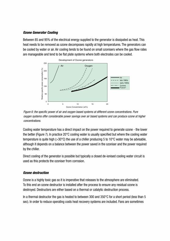
Air based systems are typically restricted to applications where the ozone demand is low (<2kg/h) or where an ozone concentration of less that 4% (or 6% depending on the cost of power) is acceptable. These are typically drinking water applications, however, even here oxygen based systems are becoming more popular because they have no need for extensive gas preparation systems, they are smaller, require less maintenance and have lower specific energy (Figure 6) requirements.
The selection of an oxygen based system is almost always driven by economics although process consideration can play a major role. The process advantages of high ozone concentrations are often the critical deciding factor due to the benefits it provides such as in paper bleaching and waste water treatment. For smaller systems (<50kg/h) the additional operating costs associated with oxygen are often balanced by the reduced capital cost, lower maintenance and lower specific power associated with oxygen based systems. In fact for large systems (>100kg/h) this is always the case unless very cheap power is available.
Oxygen can either be supplied as a liquid or can be generated on site. Typically small systems are supplied with liquid as this is cheaper than on-site production provided the plant is not in a remote location. For larger systems (5 to 150 tonnes O2/day) oxygen can be produced by vacuum swing absorption (VSA) process or for requirements in excess of 80 tonnes O2/day, by cryogenic distillation.
Figure 5: The effect of trace gases on the ozone yield. Nitrogen can be seen to have a positive effect at low concentrations
Volume % Diluent (in Oxygen)
105
100
95
90
85
80
750 10 20 30 40 50
NitrogenArgon
Carbon Dioxide
Ozone Generator Cooling
Between 85 and 95% of the electrical energy supplied to the generator is dissipated as heat. This heat needs to be removed as ozone decomposes rapidly at high temperatures. The generators can be cooled by water or air. Air cooling tends to be found on small ozonisers where the gas flow rates are manageable and tend to be flat plate systems where both electrodes can be cooled.
Cooling water temperature has a direct impact on the power required to generate ozone - the lower the better (Figure 7). In practice 20°C cooling water is usually specified but where the cooling water temperature is quite high (>30°C) the use of a chiller producing 5 to 10°C water may be advisable, although it depends on a balance between the power saved in the ozoniser and the power required by the chiller.
Direct cooling of the generator is possible but typically a closed de-ionised cooling water circuit is used as this protects the ozoniser from corrosion.
Ozone destruction
Ozone is a highly toxic gas so it is imperative that releases to the atmosphere are eliminated. To this end an ozone destructor is installed after the process to ensure any residual ozone is destroyed. Destructors are either based on a thermal or catalytic destruction process.
In a thermal destructor the gas is heated to between 300 and 350°C for a short period (less than 5 sec). In order to reduce operating costs heat recovery systems are included. Fans are sometimes
Figure 6: the specific power of air and oxygen based systems at different ozone concentrations. Pure oxygen systems offer considerable power savings over air based systems and can produce ozone at higher concentrations.
Development of Ozone generators
0
50
100
150
200
250
0 5 10 15 20
Ozone Concentration (wt%)
Rel
ativ
e sp
ecifi
c po
wer
con
sum
ptio
n (%
)
Air
late 1980s
early 1990s
CurrentFuture?
Air Oxygen

provided to move gas through the system. This is the most commonly used method although for smaller systems catalytic destruction is an economical alternative. Here the gas is passed over a metal, metal oxide and/or carbon catalyst which decomposes the residual ozone. Selection of the catalyst is critical as they can be poisoned by nitrogen oxides, chlorides, sulphides etc.
Oxygen Re-use and Recycle
Another economic consideration is the re-use of the oxygen in the off-gas either in another part of the plant or by recycling it back to the ozoniser. Typically recycling back to the ozoniser is only viable for large scale systems (>30kg/h) although smaller systems have been installed. There are essentially two ways of recycling the oxygen; long loop and short loop.
In the long loop process the oxygen is recycled after it has been in contact with the process. This means that the gas is saturated with water and may have stripped nitrogen, hydrocarbons and other contaminants from the process. These have to be removed prior to the oxygen being re-used for ozone generation, involving extensive gas preparation systems, the capital investment for which must be balanced against the cost savings in oxygen.
In the short loop recycle systems the ozone is separated from the oxygen prior to the process by absorbing the ozone onto a carrier. Then the oxygen can be re-used without further treatment and the ozone is desorbed into either nitrogen or dry air. The most commonly used absorbent is silica gel but this needs to be cooled to stabilise the ozone. Recently a process using a zeolite has been developed which works at ambient temperatures.
0 10 20 30 40 50 60Cooling Water Temperature (°C)
Rel
ativ
e O
zone
Out
put
(%
) 105
100
95
90
85
80
Figure 7: The effect of cooling water temperature on the ozone yield. Lower cooling water temperatures increase generator yield or at constant yield reduce the power consumption. The savings, however, rarely justify the use of a chiller.
Ozone Dissolution
An efficient process relies on the efficient use of ozone and hence its efficient dissolution. Traditionally bubble column systems were used. Here ozone is injected into the base of a reactor vessel with the help of sparge tubes or diffuser plates which create small bubbles. These systems are still finding widespread use today especially for applications with a low specific ozone dosage and concentrations such as drinking water. They are typified by a low energy input but also with a low mass transfer rate which results in large reactors.
Venturi injection systems use more power but achieve higher mass transfer rates and are more applicable to high ozone dosages and concentrations. Here the gas is disintegrated into fine bubbles as a result of high shear forces exerted by a liquid stream. Typically a narrow liquid jet passes through a gas filled chamber at high velocity. As the liquid passes through the chamber it entrains gas. The liquid jet then passes into a venturi shaped diffuser which converts the velocity energy into pressure energy. The mixture is then either injected directly into a pipeline (low dosages) or into the base of a reaction vessel.
These are the two most commonly used systems, although numerous others are available. One recent development worth mentioning is the Impinging Zone reactor7. This novel design achieves very high mass transfer rates for a very low power input.
Henry’s law of solubility
Henry’s law simply states that for dilute concentrations of gasses an equilibrium exists between the concentrations of the compound in the gas and the concentrations in the liquid. The concentration of the compound in the liquid is defined in terms of a mole fraction. This is the moles of the component in a given volume divided by the total number of moles (all compounds) in that volume. The concentration in the gas is best defined as the partial pressure of the compound and this is simply the gas pressure multiplied by the mole fraction of the component in the gas.
Henry’s law is defined by the following equation:
Py=Ha•x
Where:
Py partial pressure of ozone in the gas (bar)
x molar fraction of ozone in the liquid phase
Ha Apparent Henry’s constant (bar/l.mol)
Henry’s law constants are determined experimentally and are dependent on numerous factors such as temperature, pH and ionic strength. Below are some of the correlations which have been determined for ozone:
For water4 valid: T = 273 to 323K
at pH2 lnHa = 20.43 – 3501/T
at pH7 lnHa = 17.87 – 2839/T
Alternatively5 the following correlation takes into account the effect of pH:
valid: T = 277-333K & pH = 0.65-10.2
Ha = 3.79 x 10⁻⁷ x [OH-]0.035 x exp(-2428/T)

SummaryThe design of an efficient ozone treatment system is dependent on the selection of the right ozone generator. The capital cost and operating cost of the generator are in turn dependant on various factors such the gas feed used, the supply pressure and ozone concentration required and the cooling water temperature. Of these the selection of the ozone concentration is the most critical. The choice of concentration can be dominated by its final use (pulp bleaching, chemical synthesis) or can be determined on purely economic grounds. In general, however, it is a combination of the two which means that the selection of the ozoniser should never be made in isolation of the whole plant as the improved reaction kinetics and mass transfer rates associated with higher concentrations could be of overriding importance.
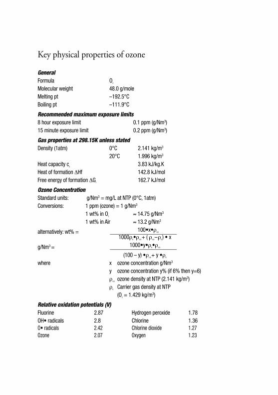
Key physical properties of ozone
General Formula O3 Molecular weight 48.0 g/mole Melting pt –192.5°C Boiling pt –111.9°C
Recommended maximum exposure limits 8 hour exposure limit 0.1 ppm (g/Nm3) 15 minute exposure limit 0.2 ppm (g/Nm3)
Gas properties at 298.15K unless stated Density (1atm) 0°C 2.141 kg/m3
20°C 1.996 kg/m3
Heat capacity cp 3.83 kJ/kg.K Heat of formation ΔHf 142.8 kJ/mol Free energy of formation ΔGf 162.7 kJ/mol
Ozone Concentration Standard units: g/Nm3 = mg/L at NTP (0°C, 1atm) Conversions: 1 ppm (ozone) = 1 g/Nm3
1 wt% in O2 ≈ 14.75 g/Nm3
1 wt% in Air ≈ 13.2 g/Nm3
≈ 100•x•ρΟ3alternatively: wt% = ________________________
1000ρG•ρΟ3 + ( ρ
Ο3 – ρG ) • x
1000•y•ρG•ρΟ3g/Nm3 = ________________________
(100 – y) •ρΟ3 + y •ρG
where x ozone concentration g/Nm3
y ozone concentration y% (if 6% then y=6) ρ
Ο3 ozone density at NTP (2.141 kg/m3) ρG Carrier gas density at NTP (O2 = 1.429 kg/m3)
Relative oxidation potentials (V) Fluorine 2.87 Hydrogen peroxide 1.78 OH• radicals 2.8 Chlorine 1.36 O• radicals 2.42 Chlorine dioxide 1.27 Ozone 2.07 Oxygen 1.23

References
1 Health and Safety Executive, Ozone: health hazards and precautionary measures, Guidance Note EH38, 1983
2 J.Hoigné and H.Bader, Ozonation of water: selectivity and rate of oxidation of solutes, Procedures of the 3rd IOA Congress, Paris, 1977
3 J.Hoigné and H.Bader, Ozone initiated oxidations of solutes in waste water: a reaction kinetic approach, Progress in water technology, 1978, Vol 10 p657
4 A. Ouederni et al., ozone absorbtion in water: mass transfer and solubility, Ozone science and engineering, 1987 Vol 9 p 1
5 J. Roth and D.Sullivan, Solubility of ozone in water, Industrial engineering and chemistry fundamentals, 1981, Vol 20 p137
6 Health and Safety Executive, Occupation exposure limits EH40, 19987 Air Products Knowledge Paper No.2, Efficient use of Ozone with the Chemox™ SR reactor*
General references
a B. Langlais, D. Reckhow and D. Brink, Ozone in water treatment: application and engineering, publ.: American water works association(AWWA) research foundation, 1991
b Kirk-Othmar, Encyclopaedia of Chemical Technology 2nd Ed., publ. Interscience, Vol 14 p410-432
* Available through The Environmental Marketing Manager, Air Products Plc, European Technology Group, Hampshire International Business Park, Basingstoke, Hampshire RG24 8FE UK. Tel: +44 (0) 1256 706117


Air Products PLC Hersham Place, Molesey Road Walton-on-Thames Surrey KT12 4RZ United KingdomTel +44(0)1932 249200 Fax +44(0)1932 249565
tell me morewww.airproducts.com
© Air Products and Chemicals. Inc. 1999 000-00-000-??