
Oxford PlasmaLab System 100 Multipurpose Plasma … · · 2017-05-09Oxford PlasmaLab System 100...
18
Page | 1 Oxford PlasmaLab System 100 Multipurpose Plasma Etcher Users Manual Coral name: Oxford Etcher 2 Model: Oxford PlasmaLab System 100 Location: Nanofab, Building 215, Room A106 Contact: [email protected]
Transcript of Oxford PlasmaLab System 100 Multipurpose Plasma … · · 2017-05-09Oxford PlasmaLab System 100...

Page | 1
Oxford PlasmaLab System 100 Multipurpose Plasma Etcher
Users Manual
Coral name: Oxford Etcher 2 Model: Oxford PlasmaLab System 100 Location: Nanofab, Building 215, Room A106 Contact: [email protected]

Page | 2
OVERVIEW:
Operator interface

Page | 3
Operation
Logging on
The tool is interlocked by Coral. Please logging on Coral as a user to access the tool.
Only qualified user can operate the tool!
Check the status before operation.
Chamber process page and Service mode page, give the status of the system and process
chamber.
A typical system alert is shown below.
Typical system alert
There are three categories of alert indicated by the colour and text displayed in the banner and
dialogue:
Blue Warning e.g. water flow low.
Yellow Hazard – not currently used.
Red Process abort, e.g. high-reflected RF power.

Page | 4
A user logged on at any access level can close the alert dialogue, but only a user logged on as a
system manager can clear the alert banner from the menu bar. The dialogue options are:
Accept button: System Managers only. Clear the alert and log it.
Next button: View the next alert.
Cancel button: System Manager only. Clear the alert; do not log it.
Continue button: Close the alert dialogue box – the alert banner remains displayed on the menu
bar.
Note that option buttons that are not available (i.e. Accept and Cancel due to user ‘logged on’
status and Next when there is only one active alert) are greyed out.
The alert message usually contains an adequate description of the detected event. If it is a service
fault (water flow, purge gas etc.) then verify that the service is available to the machine as soon
as possible. Depending on the nature of the service, the system may allow the machine to
continue to operate, so that the current process can be completed. Do not start a new process
before checking the service.
The red alerts are often due to a process setpoint being out of tolerance for too long. In these
cases, the process is halted by the system. If it is authorised to resume processing with a
parameter deviation then:
1) Check the most recent process log to find the process time remaining.
2) Construct a new process with a modified process time and check the ‘Ignore tolerance’ option.
Note that this removes all tolerance checking. The machine should be monitored by an operator
for further deviations when operated in this condition.
Loading sample
Chamber and load lock are in vacuum at idle statue so please vent the load lock for sample
loading
Page | 5
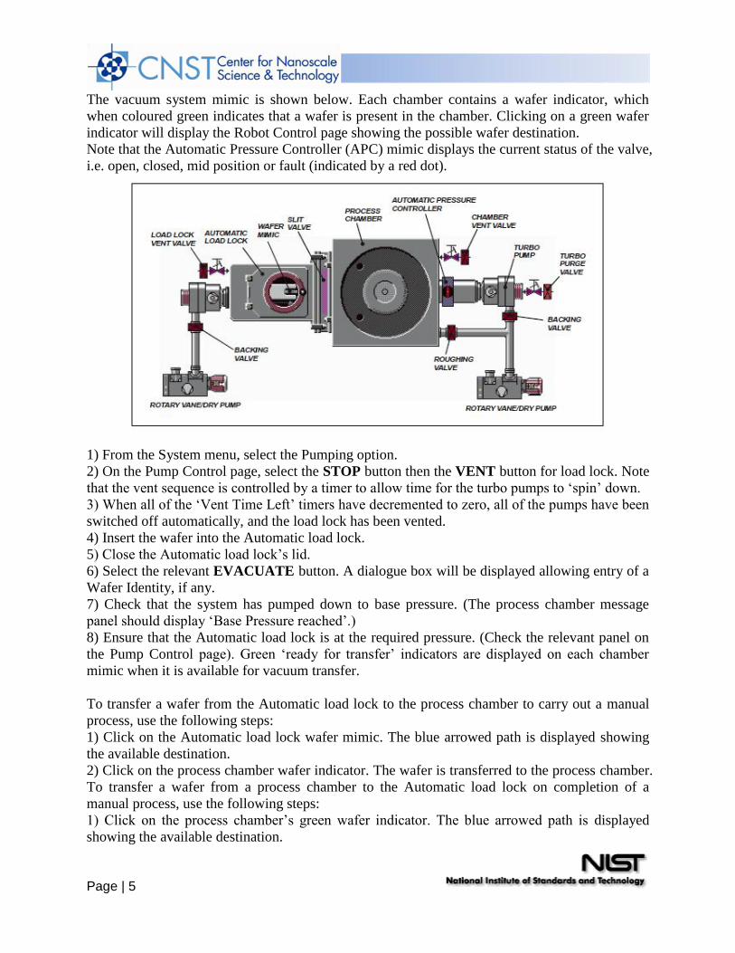
The vacuum system mimic is shown below. Each chamber contains a wafer indicator, which
when coloured green indicates that a wafer is present in the chamber. Clicking on a green wafer
indicator will display the Robot Control page showing the possible wafer destination.
Note that the Automatic Pressure Controller (APC) mimic displays the current status of the valve,
i.e. open, closed, mid position or fault (indicated by a red dot).
1) From the System menu, select the Pumping option.
2) On the Pump Control page, select the STOP button then the VENT button for load lock. Note
that the vent sequence is controlled by a timer to allow time for the turbo pumps to ‘spin’ down.
3) When all of the ‘Vent Time Left’ timers have decremented to zero, all of the pumps have been
switched off automatically, and the load lock has been vented.
4) Insert the wafer into the Automatic load lock.
5) Close the Automatic load lock’s lid.
6) Select the relevant EVACUATE button. A dialogue box will be displayed allowing entry of a
Wafer Identity, if any.
7) Check that the system has pumped down to base pressure. (The process chamber message
panel should display ‘Base Pressure reached’.)
8) Ensure that the Automatic load lock is at the required pressure. (Check the relevant panel on
the Pump Control page). Green ‘ready for transfer’ indicators are displayed on each chamber
mimic when it is available for vacuum transfer.
To transfer a wafer from the Automatic load lock to the process chamber to carry out a manual
process, use the following steps:
1) Click on the Automatic load lock wafer mimic. The blue arrowed path is displayed showing
the available destination.
2) Click on the process chamber wafer indicator. The wafer is transferred to the process chamber.
To transfer a wafer from a process chamber to the Automatic load lock on completion of a
manual process, use the following steps:
1) Click on the process chamber’s green wafer indicator. The blue arrowed path is displayed
showing the available destination.

Page | 6
2) On the Automatic load lock mimic, click on the wafer indicator. The wafer is transferred to
the Automatic load lock.
Manual wafer handling

Page | 7
Creating and editing recipes
Steps
Recipe steps are stored in the Step Library list. The list can contain any number of steps,
depending on available hard disk space. When the displayed list is full, it becomes scrollable to
allow you to view all of the list contents.
To create a new recipe step, use the following procedure:
1) In the Step Library panel, select the NEW button. The Step Edit page is displayed.
2) Enter the step parameters as required, then click on OK. The step is automatically saved.
To create a recipe step, based on an existing recipe step, use the following procedure:
1) Select a recipe step from the Step Library list, i.e. click on it to highlight it.
2) Select the COPY button. Enter a new step name.
3) Edit the step parameters as required, then click on OK. The new recipe step is automatically
saved.
To edit an existing recipe, use the following procedure:
1) Select a recipe step from the Step Library list, i.e. click on it to highlight it.

Page | 8
2) In the Step Library panel, click on the Edit button.
3) Edit the step’s process parameters as required, then click on OK. The step is automatically
saved.
NOTE: Changing an existing recipe step will not alter saved recipes, which use the old version
of that step.
To delete a recipe step, use the following procedure:
1) Select the recipe step from the Step Library list, i.e. click on it to highlight it.
2) Select the DELETE button; the selected recipe step is deleted.
Recipes
Recipes are ‘built’ using existing recipe steps, and edited as required.
Within a recipe, steps can be manipulated using the Step Commands pop-up menu (accessed by
clicking on the Recipe Steps field).
Step Commands pop-up menu
The Step Commands pop-up menu provides the following options:
Edit Step Enables the selected (highlighted) step to be edited.
Repeat Step Repeats all subsequent steps until a Loop Step is reached. This group of steps can
be repeated any number of times. (When you select this option, you are prompted to enter the
number of times the group of steps is to be repeated.)
Loop Step Terminates a Repeat Step group.
Insert Step Creates a 'gap' above the selected step to allow another step to be dragged into the
list.
Delete Step Deletes the selected step from the list.
Cancel Closes the Step Commands pop-up menu.
To build a recipe, use the following procedure:
1) In the Recipe panel, select the NEW button.
2) Click on a recipe step in the Step Library list, hold the left mouse button down then drag the
mouse pointer to the Step Name field next to the asterisk (*) then release the mouse button. The
step name is displayed in the Step Name field.

Page | 9
3) Repeat 2) as required to add further steps to the recipe. Note that once you have filled the Step
Name field, the recipe step list becomes scrollable, enabling you to add a maximum total of 1000
steps.
4) To remove a step from the list, click on it to highlight it then select the Delete step button
from the Step Commands pop-up menu. Any further steps will move up the list by one place.
5) To add a step before an existing step, click on the existing step then select the Insert step
button from Step Commands pop-up menu. The selected step and all those following it will
move down the list by one place. You can then drag another step from the Step Library list into
the now vacant field.
6) When all steps have been added, enter a time into the Data Log Interval field, then enter a
name for the recipe in the Recipe Name field. Finally, select the SAVE button.
To edit a recipe, use the following procedure:
1) Select the LOAD button, then select the recipe to be edited.
2) In the Step Commands pop-up menu, click on the Edit Step button, then edit the process
parameters as required. Note that editing a recipe step will not affect the associated step, i.e. a
step having the same filename, in the Library of Available Steps.
3) To remove a step from the list, click on it to highlight it then select the DELETE STEP
button from the Step Commands pop-up menu. Any further steps will move up the list by one
place.
4) To add a step before an existing step, click on the existing step then select the
INSERT STEP button. The selected step and all those following it will move down the list by
one place. You can then drag another step from the Step Library list into the now vacant field.

Page | 10
Process window
The facilities available on the above process window are:
Process chamber message field
Displays context related messages about the process chamber.
Transfer status/
Log Comment message field
Displays context related messages about wafer transfer status. This field is also used to enter
comments about the current process run which can be viewed on the log viewer page.
Wafer status field
Displays context related messages about the wafer currently in the
Automatic load lock or process chamber.
Log Comment button
Allows comments about the current process to be entered in the
Transfer status/Log Comment message field. While entering a comment, the button title changes
to OK to allow the comment to be accepted.
Leak Detection button Displays the leak detection page.
Start button Select to start a manual process run using the parameters set on this page.
Stop button Select to stop the current process step.
Pause button Select to pause the current process.
Jump button Select to jump to the next process step.
Page | 11
Recipe message field
Displays information about the current recipe, step, loaded wafer identity, etc..
Step Time fields Enter the required step time in hours:minutes:seconds. While a process is
running, the adjacent field displays the time remaining to the end of the step.
Log Interval fields
Enter the interval required between data logging events.
Process status field
Indicates the process status; either Ready, Auto or Manual
Pump to Pressure checkbox
Select to create a pumping step. The system will pump down until the demanded pressure is
reached. The step will remain active until this condition is met. Both RF Generators are
automatically switched off during the step. (� Indicates selected). All setpoints are automatically
set to zero, except for base pressure.
Pressure fields Enter the required Process Chamber pressure for the step. The measured pressure
is displayed in the adjacent field.
Ignore Tolerances checkbox
Select to disable tolerance
RF Generator panel
Enter the required forward power. The forward power, reflected power, power ON/OFF status
and DC bias are displayed.
Clicking the Set Fwd Power button toggles the demand between a forward power set point and a
DC bias set point. If a DC bias demand is set, the RF power will be varied to try to achieve the
required bias.
Use this facility with care: if the plasma does not strike or if the DC bias cannot be read (by
covering the table with insulator), then the RF power will increase to maximum.
RF AUTOMATCH panel
CAPACITOR 1 field
Enter the required position for variable AMU Capacitor 1. The position can be set between 0%,
minimum capacitance, and 100%, maximum capacitance. The capacitor position read back is
displayed.
CAPACITOR 2 field
Enter the required position for variable AMU Capacitor 2. The position can be set between 0%,
minimum capacitance, and 100%, maximum capacitance. The capacitor position read back is
displayed.
AUTO button
Select to enable the AMU to tune automatically when the RF generator is switched on. When the
RF generator is switched off, the capacitors return to the park position.
MANUAL button
Select to enable the AMU to move the capacitors to the values defined in the CAPACITOR 1
and CAPACITOR 2 fields; the capacitors will remain in these positions.
HOLD button
Select to enable the AMU to tune automatically when the RF generator is switched on. When the
RF generator is switched off the capacitors remain at the last position.
ICP GENERATOR panel

Page | 12
Enter the required forward power. The forward power, reflected power, ON/OFF status are
displayed. ICP
AUTOMATCH panels
CAPACITOR 1 field
Enter the required position for variable AMU Capacitor 1. The position can be set between 0%,
minimum capacitance, and 100%, maximum capacitance. The capacitor position read back is
displayed.
CAPACITOR 2 field
Enter the required position for variable AMU Capacitor 2. The position can be set between 0%,
minimum capacitance, and 100%, maximum capacitance. The capacitor position read back is
displayed.
AUTO button
Select to enable the AMU to tune automatically when the RF generator is switched on. When the
RF generator is switched off, the capacitors return to the park position.
MANUAL button
Select to enable the AMU to move the capacitors to the values defined in the CAPACITOR 1
and CAPACITOR 2 fields; the capacitors will remain in these positions.
HOLD button
Select to enable the AMU to tune automatically when the RF generator is switched on. When the
RF generator is switched off the capacitors remain at the last position.
ENDPOINT panel
Enter a number 0 to 7 to select an endpoint script to run. Refer to the
Verity SD 1024 ‘standalone’ endpoint system manual for details. Note this system has a
‘standalone’ Endpoint Detection System. When the RF power is switched on, a start signal is
sent to the Endpoint
Detection System, which will return an endpoint signal when an endpoint is detected. On receipt
of the endpoint signal, the process will terminate immediately ignoring any preset process length.
CRYO panel Enter the required table temperature. The current table temperature is displayed.
HELIUM BACKING panel
Enter the required backing pressure. The current pressure (Torr) and flow rate (sccm) are
displayed. The open/closed status of the control valve is displayed.
APC CONTROLLER panel
Select either the Pressure or the Position button. Enter the required Chamber Pressure or APC
valve position. The current Process Chamber pressure, Valve Position and valve status are
displayed.
The low pressure strike feature allows plasma processing at low pressures. When the gas
pressure is too low, it is not possible to strike a plasma; however it is possible to sustain a plasma
to very low pressures once it has been ignited. This software feature enables the user to raise the
pressure temporarily, strike a plasma, and automatically reduce the pressure to the desired value
for processing.
The three data fields and their effects are:
LOW PRESSURE STRIKE panel
Strike Pressure field
DC bias Minimum field
Ramp Rate field

Page | 13
Enter the value in mTorr at which the RF should turn on and strike the plasma. If a zero is
entered, the feature is disabled and the RF will turn on once the pressure has stabilised at the
requested process pressure.
Enter a positive number for the minimum DC bias value expected once the plasma has struck.
Enter zero if DC bias cannot be read because the substrate (and any wafer clamp) completely
cover the electrode, or if the electrode has an insulating coating. A non-zero value is used by the
software to detect if the plasma has been properly established. If a zero is entered, then the
software assumes the plasma has struck once the RF reflected power goes low.
Enter a number to set the rate at which the pressure is reduced from the strike value to the set
point. The higher the number entered, the faster the transition to process conditions will be. Note
that too high a value can cause the plasma to go out if the plasma impedance changes faster than
the RF matching unit can track.
Etching
An automatic process run can be carried out by a user logged on.
1) Select the Process menu, then the Recipe option. Click on the Load button then select the
required recipe.
2) Click on the Run button. This will start wafer transfers and wafer processing.
3) When the ‘Process Complete’ message is displayed, select the Pump Control page and move
the wafer from the process chamber to the Automatic load lock using the same method as the
transfer in.
4) Open the Automatic load lock’s lid and remove the wafer.
Process Datalog
All processes are automatically data-logged. The interval between logging events is set in the
Recipe screen.
The Process Datalog facility allows you to view process data runs and associated comments. The
facility comprises three pages:
a) SELECT LOG page – allows you to select the process data to view.
b) RUN LOG page – lists the selected process data, for all runs except Leak detection runs and
MFC calibration runs, with respect to time.
c) Leak detection and MFC calibration log page – displays the Leak detection runs and MFC
calibration runs in text and graphical formats. These pages are described in the following text.
The Select Log page is displayed by selecting the Process button, then the Log View option.

Page | 14
Select Log page
The page comprises a list of logged events, which can be filtered by type, batch name and time.
When the required events have been selected, they can be viewed on a Log View page.
The facilities provided on the page are as follows:
List of logged events
Displays a list of logged events in a date/time sequence. Each event is identified by an icon, date,
time, title, duration, name and comments (if present). An event is selected (highlighted) by
clicking on it.
Delete button Deletes the selected event
Undo button Undo the last action
Save As Text button
Save the selected event as a text file for use in spreadsheets etc.
View Run button
Opens either the Run Log page (see sub-section 5.7.2, page 5-29) or, if either a Leak detection
run ( ) or MFC calibration run ( ) is selected, the Leak Detect and MFC calibration log page (see
sub-section 5.7.3, page 5-30) with the selected log data displayed.
Filter by Type list

Page | 15
A list of event types with associated checkboxes. Use this panel to select the events to display in
the Event list. A checkbox showing an ‘x’ indicates that the associated event type will not be
displayed. A checkbox showing a ‘�’ indicates that the associated event type will be displayed.
Filter by Batch Name field
Enter a batch name to list only logged events associated with that batch.
Filter by time fields and buttons
Use these controls to select events occurring in a time range to be displayed.
Hide items before selection button
Displays all events after and including the highlighted event.
Hide items after selection button
Displays all events before and including the highlighted event.
Show all items button
Displays all previously hidden events.
Any logged process run can be saved at text and then opened in Excel for viewing, analysing, etc.
To do this, use the following steps:
1) On the Select Log page, select the required process run (any multiple steps will be
automatically highlighted).
2) Select the Save As Text button. The Save As dialogue is displayed.
3) Navigate to the target location for the log text file, enter a filename and in the ‘Save as type:’
field select ‘Log Text Files (*.Txt)’ from the drop-down list. If saving to a floppy disk, label it
and insert into the drive now.
4) Select the Save button. The text file is saved in your chosen location.
5) Start Excel and then in the File menu, select the Open option. The ‘Open’ dialogue is
displayed.
6) Navigate to the location of the saved text file and in the ‘Files of type:’ field, select ‘All Files
(*.*)’ from the drop-down list. Select the required text file and then select the Open button. The
‘Text Import Wizard – Step 1 of 3’ dialogue is displayed:

Page | 16
7) In the ‘Original data type’ panel, select the ‘Delimited’ option and then select the
Next > button. The ‘Text Import Wizard – Step 2 of 3’ dialogue is displayed:
8). In the ‘Delimiters’ panel, select the ‘Comma’ checkbox. Select the Next > button. The

Page | 17
‘Text Import Wizard – Step 3 of 3’ dialogue is displayed:
9) In the ‘Column data format’ panel, ensure that the ‘General’ option is selected and then select
the Finish button. The process run log data is now displayed in the Excel worksheet.
10) Adjust the column widths so that all text is visible and then save the spreadsheet.
Run log
The Run Log page is accessed from the Select Run page by clicking on the View Run button
with any process run other than a leak detection run or MFC calibration run.
The page displays the Parameters, Demands and Readbacks for the selected log data.
The facilities provided on the page are as follows:
Select Run button
Displays the Select Log page.
Log information panel
Displays details about the selected log data.
Parameter list Lists the logged parameter names
Demand list Displays the demanded parameter value
Readbacks list Displays the logged parameter values with respect to time at the log intervals
specified for the process run. The list can be scrolled horizontally either by single readbacks or
by page. The list can also be scrolled vertically to display further steps (for multi-step recipes).

Page | 18
Run log page