Remote Power-Off Device - APC UPS, APC Battery Replacement ...

294000.10039 Rev A
Oxford®/Hoyer®
Professional SeriesSERVICE MANUAL
Adaptive Power Cradle

2
294000.10039 Rev A
CONTENTS
Pages 3 - 4
Inspection Criteria of the Oxford/Hoyer APC
Page 5
Testing of the Oxford/Hoyer APC
Pages 6 - 11
Service and Maintenance Schedule for the Oxford/Hoyer APC
Pages 12 - 14
Fault Finding
Page 15
Exploded View of the Oxford/Hoyer APC
Page 16
Parts List of the Oxford/Hoyer APC
Page 17
LOLER (UK only): Thorough Examination Report
Page 18 - 23
Appendix A
Page 24
Blank Notes Page

3
294000.10039 Rev A
INSPECTION CRITERIAJoerns Healthcare recommends a thorough inspection and test of the Oxford/Hoyer APC and its associated Lift, lifting accessories,slings etc. is carried out every six months. The examination and test should be conducted according to the recommendations andprocedures below. Joerns Healthcare recommends that authorized service dealers should carry out maintenance, inspection andcertified testing only.
Note: These recommendations are in compliance with the requirements of Statutory Instrument 1998 No2307 Health and Safety:The Lifting Operations and Lifting Equipment Regulations 1998. (LOLER)
This is a UK regulation. Outside the UK please check your local requirements.
FRAMEWORK
Check the cradle for freedom of rotation and swing.Check for wear on the central pivot and wear washer. See Fig. 1, Appendix A.Check the slick pin is correctly fitted and securely locating the fulcrum pin to the boom. See Fig. 2, Appendix A.Check for adequate padding.Check condition of the handgrip.Check that the pivot nut is located onto the threaded stud. See Fig. 3, Appendix A.Check wear on pivot joint washer. See Fig. 4, Appendix A.Check Securi3 location pins are securely fitted to the frame. See Fig. 5, Appendix A.Inspect for excessive wear on the Securi3 location pins.Inspect all welded joints on the cradle frame.Maintenance: - Lubricate main suspension point, centre pivot, and cradle pivot points as necessary.
ACTUATOR
The actuator should require no maintenance.Check that the circlips are fitted to the actuator pivot pins and correctly located onto the pivot pins. See Fig. 6, Appendix A.Check that the actuator operates in a smooth manner in both directions.Confirm power cut-out at both ends of travel.Check for the free movement of pivot points.Check for wear on the mounting brackets and upper and lower pivot pins. Fig. 7 and 8, Appendix A.Listen for unusual noise which may indicate future break down.
CONTROL BOX
Check that the control box is securely fitted to the cradle. The control box has a magnetic backing and one securing screw at theback. See Fig. 9, Appendix A.Check that the contacts are clean within the control box area that houses the battery. See Fig. 10, Appendix A.Check that the wire connections into the control box are correct and clipped in place. See Fig. 12, Appendix A.
BATTERY
Confirm the control box is not sounding audible low battery alarm when operating.Check that the contacts are clean. Fig. 13, Appendix A.Check that the casing is undamagedCheck that the battery locates correctly into the control box.Check that the battery locates correctly into the charging unit.
4
294000.10039 Rev A
INSPECTION CRITERIA
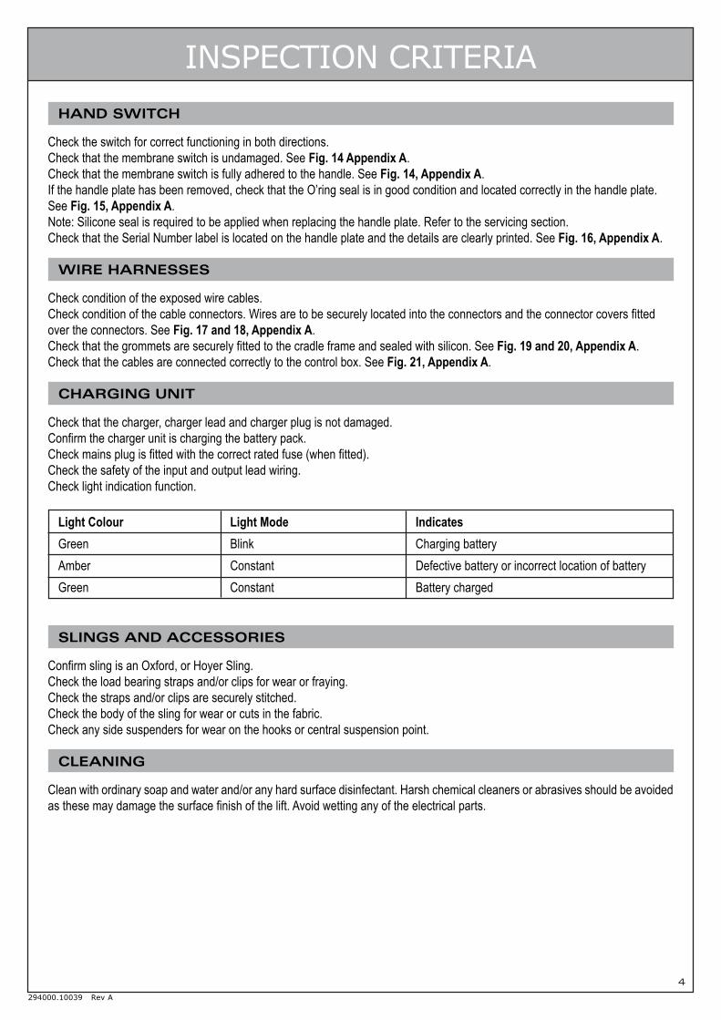
HAND SWITCH
Check the switch for correct functioning in both directions.Check that the membrane switch is undamaged. See Fig. 14 Appendix A.Check that the membrane switch is fully adhered to the handle. See Fig. 14, Appendix A.If the handle plate has been removed, check that the O’ring seal is in good condition and located correctly in the handle plate.See Fig. 15, Appendix A.Note: Silicone seal is required to be applied when replacing the handle plate. Refer to the servicing section.Check that the Serial Number label is located on the handle plate and the details are clearly printed. See Fig. 16, Appendix A.
WIRE HARNESSES
Check condition of the exposed wire cables.Check condition of the cable connectors. Wires are to be securely located into the connectors and the connector covers fittedover the connectors. See Fig. 17 and 18, Appendix A.Check that the grommets are securely fitted to the cradle frame and sealed with silicon. See Fig. 19 and 20, Appendix A.Check that the cables are connected correctly to the control box. See Fig. 21, Appendix A.
CHARGING UNIT
Check that the charger, charger lead and charger plug is not damaged.Confirm the charger unit is charging the battery pack.Check mains plug is fitted with the correct rated fuse (when fitted).Check the safety of the input and output lead wiring.Check light indication function.
Light Colour Light Mode IndicatesGreen Blink Charging batteryAmber Constant Defective battery or incorrect location of batteryGreen Constant Battery charged
SLINGS AND ACCESSORIES
Confirm sling is an Oxford, or Hoyer Sling.Check the load bearing straps and/or clips for wear or fraying.Check the straps and/or clips are securely stitched.Check the body of the sling for wear or cuts in the fabric.Check any side suspenders for wear on the hooks or central suspension point.
CLEANING
Clean with ordinary soap and water and/or any hard surface disinfectant. Harsh chemical cleaners or abrasives should be avoidedas these may damage the surface finish of the lift. Avoid wetting any of the electrical parts.
5
294000.10039 Rev A
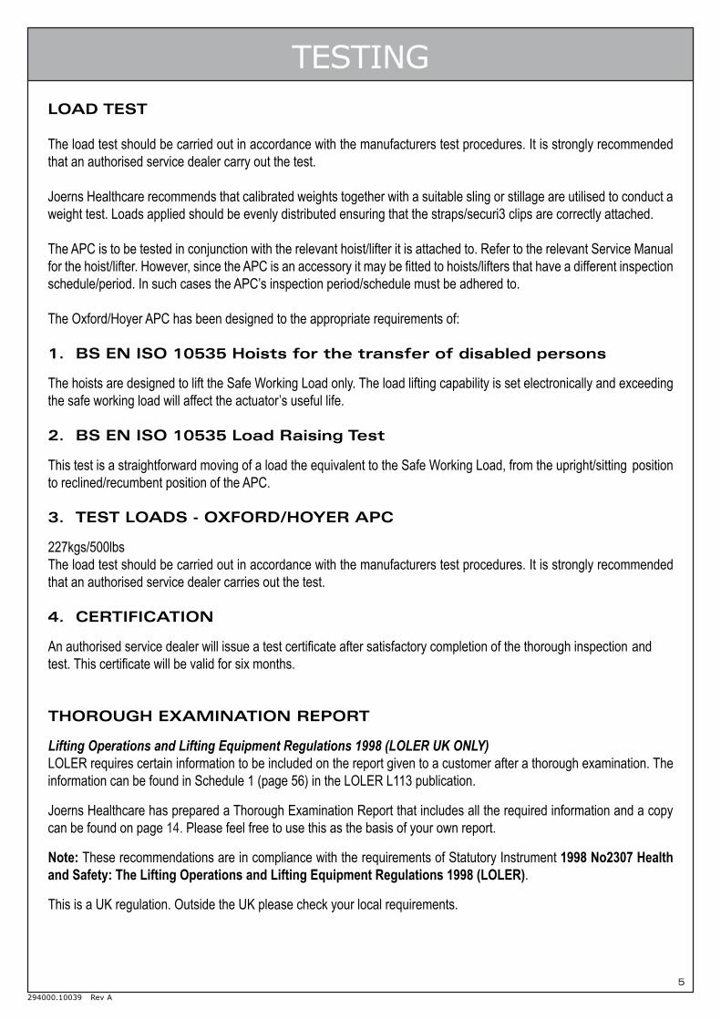
TESTINGLOAD TEST
The load test should be carried out in accordance with the manufacturers test procedures. It is strongly recommendedthat an authorised service dealer carry out the test.
Joerns Healthcare recommends that calibrated weights together with a suitable sling or stillage are utilised to conduct aweight test. Loads applied should be evenly distributed ensuring that the straps/securi3 clips are correctly attached.
The APC is to be tested in conjunction with the relevant hoist/lifter it is attached to. Refer to the relevant Service Manualfor the hoist/lifter. However, since the APC is an accessory it may be fitted to hoists/lifters that have a different inspectionschedule/period. In such cases the APC’s inspection period/schedule must be adhered to.
The Oxford/Hoyer APC has been designed to the appropriate requirements of:
1. BS EN ISO 10535 Hoists for the transfer of disabled persons
The hoists are designed to lift the Safe Working Load only. The load lifting capability is set electronically and exceedingthe safe working load will affect the actuator’s useful life.
2. BS EN ISO 10535 Load Raising Test
This test is a straightforward moving of a load the equivalent to the Safe Working Load, from the upright/sitting positionto reclined/recumbent position of the APC.
3. TEST LOADS - OXFORD/HOYER APC
227kgs/500lbsThe load test should be carried out in accordance with the manufacturers test procedures. It is strongly recommendedthat an authorised service dealer carries out the test.
4. CERTIFICATION
An authorised service dealer will issue a test certificate after satisfactory completion of the thorough inspection andtest. This certificate will be valid for six months.
THOROUGH EXAMINATION REPORT
Lifting Operations and Lifting Equipment Regulations 1998 (LOLER UK ONLY)LOLER requires certain information to be included on the report given to a customer after a thorough examination. Theinformation can be found in Schedule 1 (page 56) in the LOLER L113 publication.
Joerns Healthcare has prepared a Thorough Examination Report that includes all the required information and a copycan be found on page 14. Please feel free to use this as the basis of your own report.
Note: These recommendations are in compliance with the requirements of Statutory Instrument 1998 No2307 Healthand Safety: The Lifting Operations and Lifting Equipment Regulations 1998 (LOLER).
This is a UK regulation. Outside the UK please check your local requirements.

6
294000.10039 Rev A
SERVICE & MAINTENANCE
TOOLS REQUIRED
• Electrician’s screwdriver (to remove slick pin)• Circlip pliers (to remove the actuator)• Pozi screwdriver. (to remove the control box from mounting bracket and switch plate cover)• 17mm A/F socket set (to remove the nyloc nuts)• Vernier caliper (to measure pin and hole diameter)• Silicon seal (to seal re-wired areas)• Medium Strength Thread lock (BLUE) type
FRAMEWORK
1 The cradle fulcrum pin is held in place with a slic pin that runs through a steel outer sleeve. Remove the slic pinby depressing the security tab on the one end of the pin (an electricians screwdriver or similar type of flat bladedtool can be used), and withdraw it from the other side. See Fig. 2, Appendix A.
2 Examine the pin for signs of wear and for any deformation of the security tab. The diameter of the pin is 10mm.Reduction in diameter due to wear must not exceed 1mm before replacement.
3 Withdraw the outer sleeve bush from the boom end (hold the cradle while doing this as the cradle may fall)inspect the sleeve for wear as per the pin. See Fig. 2, Appendix A.
4 Remove the black plastic shroud (2 piece) from the spreader bar pivot and examine for damage. Do not lose thepins located inside the shroud. The shroud is an important guard against finger traps. Make sure it will performthis function. Discard and replace if necessary.
5 Take off and retain the “O” ring that holds the main pivot in the cradle’s central boss. Remove the main pivot fromthe cradle. See Fig. 22 and 23, Appendix A.
6 Examine the main pivot and the central boss for wear.
7 Main pivot: On the hoist, check for wear on the cross-hole for the fulcrum pin. The hole is 16mm in diameter;wear should not exceed 1mm on diameter or 2mm elongation before replacement. See Fig. 2, Appendix A.
8 Check the condition of the white/black acetyl wear washer that sits on the pivot shoulder. The wear washer isthere to stop metal-to-metal contact on the pivot shoulder and the central boss on the cradle assembly. If thewasher shows any signs of deformation or wear it should be replaced. See Fig. 2, Appendix A.
9 Cradle sling mounting points: Check for wear. The sling mounting points are made from 7.5mm diametermaterial. Reduction in diameter by wear should not be allowed to exceed 1mm before replacement.See Fig. 5, Appendix A.
10 Remove the domed black plastic caps that cover the cradle pivot joints. See Fig. 3 Appendix A.
11 Check the 17mm A/F Nyloc nuts that hold the cradle to the central suspension assembly are tightened to 6NM. Aminimum of one thread should be visible on the stud. See Fig. 3, Appendix A.
12 The cradle when tightened correctly should support a 5kg load or a force of 7N at the handle, and move smoothlyon the central suspension assembly. Detachment of the actuator is required to enable this check to beconducted. Refer to the Actuator section.

7
294000.10039 Rev A
SERVICE & MAINTENANCE13 Lubricate the pivot joints with any light mineral-based grease, or silicon spray.
14 Remove the nyloc nut and washer from the stud. See Fig. 24, Appendix A
NOTE: Joerns Healthcare recommends Nyloc nuts should always be replaced if undone.
15 Separate the two frame pieces so that access to the pivot washer and observation on the stud and mechanicalstop can be made. See Fig. 25 to 28, Appendix A
WARNING: When separating the two frame pieces care is needed not to trap fingers. See Fig. 26, Appendix A
16 Inspect the washer for wear. Check the stud and mechanical stop pin and mating channel. Replace any parts thatshow damage or significant wear.
17 Refit the washer to the frame and reassemble the two frame pieces.
18 Replace the washer and fit the new nyloc nut.
19 Replace the caps (ensure the cap snaps back into place).
After performing all the required actions and checks listed under “FRAMEWORK” (1 to 19) reassemble the cradle asfollows:
20 Lubricate the main pivot, fulcrum pin and sleeve with any light mineral-based grease, or silicon spray, payingparticular attention to the pivot shoulder, wear washer, and the fulcrum pin cross-hole.
21 Fit the main pivot to the spreader bar central boss. Refit the retaining “O” ring. Check rotation of the pivot in the boss.
22 Fit the black plastic shrouds to the cradle pivot and insert into the boom end. Ensure pins are fitted inside theplastic shrouds to assist assembly. Line up the holes in the boom, shrouds and pivot and insert the sleeve.
23 Insert the security pin into the outer sleeve ensuring, that the security tab is visible when it passes through theouter sleeve. An audible “click” should be heard as the tab springs into position.
NOTE: It is most important that the cradle assembly is carefully checked to ensure the wear washer is on thepivot, and the cradle is completely secure to the boom before leaving the hoist.
ACTUATOR
1 Examine the actuator mounting point. Without taking the mounting point apart check for signs of wear on the twomounting brackets and pivot pins. Check for excessive movement in the mounting. This will give a goodindication of wear but if there is any doubt the assembly should be stripped down as follows:
Removal of upper mounting:
2 Remove the circlip that secures the actuator pivot pin to the bracket and extract the pivot pin.See Fig. 29 and 30, Appendix A.
3 Examine the pivot pin for signs of wear and for firm attachment of the remaining circlip. The diameter of the pivot pinis 9.9mm. Reduction in diameter due to wear must not exceed 1mm before replacement. See Fig. 31, Appendix A.

8
294000.10039 Rev A
SERVICE & MAINTENANCE4 Examine the actuator mounting bracket on the cradle for wear on the bore of the Bracket. Diameter of the hole is
10mm wear should not exceed 1mm on diameter or 2mm elongation. See Fig. 32, Appendix A.
5 Examine the actuator top for wear. Diameter of the hole is 10mm wear should not exceed 1mm on diameter or2mm elongation. See Fig. 33, Appendix A.
6 Replace the pivot pin through the actuator and cradle bracket.
7 Fix the fulcrum pin in place using a circlip. (Suitable for groove diameter 9.3mm - Spare kit 0Y0465)
Removal of lower mounting:
8 Removal of the lower mounting point is the same process as conducted for the upper mounting.See Fig. 34 to 38, Appendix A. However it may be required to extract some cable from the frame. If this isrequired refer to section Wiring and Connections.
9 Examine the pivot pin for signs of wear and for firm attachment of the remaining circlip. The diameter of the pivotpin is 9.9mm. Reduction in diameter due to wear must not exceed 1mm before replacement.See Fig. 36, Appendix A.
10 Examine the actuator mounting bracket on the cradle for wear on the bore of the Bracket. Diameter of the hole is10mm wear should not exceed 1mm on diameter or 2mm elongation. See Fig. 37, Appendix A.
11 Examine the actuator bottom for wear. Diameter of the hole is 10mm wear should not exceed 1mm ondiameter or 2mm elongation. See Fig. 38, Appendix A.
12 Removal of the actuator can be achieved after completing activities 2 and 8. Then remove the wire harness fromthe framework following instructions identified in the Wire and Connections section.
NOTE: Joerns Healthcare recommends:
NEVER reuse circlips.ALWAYS use circlip pliers for fitting.ENSURE the circlip is properly located in the groove.
CONTROL UNIT
1 Check the engagement of the controller with the mounting. The controller has a magnetic back that allows easylocation onto the mounting bracket. The use of the screw at the back of the mounting plate ensures that thecontroller is securely fitted. To remove the control unit unplug the two connectors at the bottom (refer to nextnote) and remove location screw. See Fig. 39, Appendix A.
2 Check the connector plugs are inserted fully into the sockets on the base of the control unit. The controller isdesigned so that it does not matter which connector is fitted into the sockets. Removal of the connectors from thesockets is easily achieved by pressing down on the connector retaining clip and then pulling out the connectorfrom the socket, holding onto the connector as this is done. Do not pull on the cable as this may damage the wireconnection into the plug. See Fig. 40 and 41, Appendix A.
3 Check the contacts for the battery connection are clean and not damaged. See Fig. 42, Appendix A.

9
294000.10039 Rev A
SERVICE & MAINTENANCE4 Check the functionality of the audible signals. The signals are indicated with a long, short or multiple “beeps”.
4.1 Power On (Power is on when the battery is inserted): One extended “BEEP”
4.2 Sleep Mode: Two short “BEEPS”
4.3 Low Battery: Two short “BEEPS” repeated every 24 seconds. (charge battery)
4.4 Start Operation: Two “BEEPS” (low voltage, charge battery soon)
4.5 During Operation: One long BEEP (the battery charge is too low; only downward motion will be possible).
BATTERY
1 The battery service checks required can be conducted when servicing the control unit and the charger unit. Referto relevant sections within this manual.
2 Check the contacts on the battery connection are clean and not damaged. See Fig. 13, Appendix A.
3 Check that the casing of the battery is undamaged. See Fig. 43, Appendix A.
4 It is recommended that the battery is kept fully charged. Place the battery on charge whenever it is not in use. If itis more convenient to do so, place on charge every night. The charger will not allow the battery to overcharge.Refer to Charger section of this manual for further details to prolong the life of the battery.
HAND SWITCH AND HOUSING
1 Check that the membrane switch is firmly located to the handle. The adhesive backed switch prevents ingress ofdirt and fluids into the switch housing area. See Fig. 14, Appendix A.
2 Check that the membrane switch is not cracked.
3 Check the switch for correct functioning in both directions.
4 If the membrane switch requires replacing then peel off the switch from the housing. Gently pull out the attachedribbon cable and disconnect from the wire harness. See Fig. 44 to 46, Appendix A.
5 To replace with a new membrane switch. Clean the metal housing to remove any grease or dirt. Connect theconnector on the membrane switch to the wire harness. Remove the protective backing off the membrane switchto expose the adhesive backing and carefully locate onto the housing. Ensure that no air bubbles occur whenfitting and that the edges provide a seal onto the housing. See Fig. 47 and 48, Appendix A.
6 Remove the sealed plate from the housing by removing the two M3 pozi screws. See Fig. 49, Appendix A.
7 Examine the grommet seal for any sign of damage or distortion. This grommet seal provides ingress protectionagainst dust and fluids. Replace grommet seal if required. See Fig. 50, Appendix A.
NOTE: It is required to use silicon seal around the grommet area.
10
294000.10039 Rev A
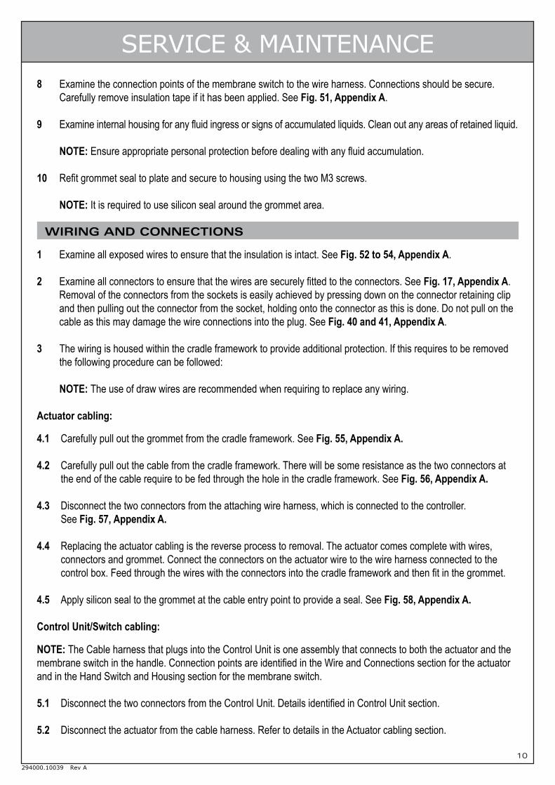
SERVICE & MAINTENANCE8 Examine the connection points of the membrane switch to the wire harness. Connections should be secure.
Carefully remove insulation tape if it has been applied. See Fig. 51, Appendix A.
9 Examine internal housing for any fluid ingress or signs of accumulated liquids. Clean out any areas of retained liquid.
NOTE: Ensure appropriate personal protection before dealing with any fluid accumulation.
10 Refit grommet seal to plate and secure to housing using the two M3 screws.
NOTE: It is required to use silicon seal around the grommet area.
WIRING AND CONNECTIONS
1 Examine all exposed wires to ensure that the insulation is intact. See Fig. 52 to 54, Appendix A.
2 Examine all connectors to ensure that the wires are securely fitted to the connectors. See Fig. 17, Appendix A.Removal of the connectors from the sockets is easily achieved by pressing down on the connector retaining clipand then pulling out the connector from the socket, holding onto the connector as this is done. Do not pull on thecable as this may damage the wire connections into the plug. See Fig. 40 and 41, Appendix A.
3 The wiring is housed within the cradle framework to provide additional protection. If this requires to be removedthe following procedure can be followed:
NOTE: The use of draw wires are recommended when requiring to replace any wiring.
Actuator cabling:
4.1 Carefully pull out the grommet from the cradle framework. See Fig. 55, Appendix A.
4.2 Carefully pull out the cable from the cradle framework. There will be some resistance as the two connectors atthe end of the cable require to be fed through the hole in the cradle framework. See Fig. 56, Appendix A.
4.3 Disconnect the two connectors from the attaching wire harness, which is connected to the controller.See Fig. 57, Appendix A.
4.4 Replacing the actuator cabling is the reverse process to removal. The actuator comes complete with wires,connectors and grommet. Connect the connectors on the actuator wire to the wire harness connected to thecontrol box. Feed through the wires with the connectors into the cradle framework and then fit in the grommet.
4.5 Apply silicon seal to the grommet at the cable entry point to provide a seal. See Fig. 58, Appendix A.
Control Unit/Switch cabling:
NOTE: The Cable harness that plugs into the Control Unit is one assembly that connects to both the actuator and themembrane switch in the handle. Connection points are identified in the Wire and Connections section for the actuatorand in the Hand Switch and Housing section for the membrane switch.
5.1 Disconnect the two connectors from the Control Unit. Details identified in Control Unit section.
5.2 Disconnect the actuator from the cable harness. Refer to details in the Actuator cabling section.

11
294000.10039 Rev A
SERVICE & MAINTENANCE5.3 Remove the housing plate on the handle and disconnect the membrane switch. The membrane switch does not
require removing when requiring the wire harness to be disconnected. After removing the housing plate, thewires are exposed to allow the connectors to be disconnected. See Fig. 59 to 61, Appendix A.
NOTE: Care must be taken with handling the ribbon cable to prevent damage.
5.4 Detach the grommet from the metal clip and carefully pull out the grommet from the cradle framework.See Fig. 62 and 63, Appendix A.
5.5 Carefully pull out the cable harness. The actuator cable is identified with the two red connectors. TheMembrane Switch cable is identified by the 4 Pin connector. See Fig. 64, Appendix A.
5.6 To replace the cable harness re-insert the cabling into the frame and feed through the connectors to theappropriate holes to allow connection to the actuator and membrane switch.
5.7 Reconnect the actuator as previously instructed earlier in this section.
5.8 Reconnect the membrane switch and refit the housing plate. Ensure that wires are free from entrapment andthat silicon seal has been applied around the grommet seal prior to securing the plate to the housing. Details arefurther explained in the Hand Switch and Housing section.

12
294000.10039 Rev A
FAULT FINDINGThe following are guidelines in determining the root cause of a problem. Should the fault not be identified then pleasecontact Customer Services/Technical Support for further assistance.
PROBLEM: Actuator does not function in either direction.
1. Check that the battery is engaged into the controllercorrectly.
2. If actuator does not work then check that battery ischarged sufficiently or replace with fully chargedbattery.
3. If not working disconnect from the controller andconnect to new controller and re-check. If actuatorworks replace the original controller.
4. If actuator does not work then remove the actuatorfrom it’s mounting points and check if it works. Ifactuator works check all pivot points and lubricate/replace parts as required.
5. If actuator does not work then disconnect theactuator from the wire harness in the frame andconnect to a new actuator. If actuator worksreplace the original actuator.
6. If actuator does not work then disconnect the handleswitch from the wire harness and reconnect a newswitch. If actuator works replace the handle switch.
7. If actuator does not work then connect the originalactuator and controller to a new wire harness andtest. If the actuator works replace the original wireharness.
Possible Fault Remedy
Actuator is damaged
Battery not engaged into controller correctly
Battery is not charged sufficiently
Controller is damaged
Pivot Points are seized
Connector to the controller is disconnected
Wire harness is damaged
Handle switch is disconnected
Handle switch is damaged
PROBLEM: Actuator making unusual noise.
1. Remove the actuator from the mounting points andcheck for free movement of the pivot points and themain pivot point for the cradle. Refit the actuator.
2. If the actuator continuous to make a similar noiseremove the actuator from it’s mounting points.Disconnect the actuator from the wire harness inthe frame and connect to a new actuator. Refit tothe mounting points and test.
Possible Fault Remedy
Actuator is damaged
Pivot Points are seized

13
294000.10039 Rev A
FAULT FINDINGPROBLEM: Cradle does not rotate. DO NOT continue using the cradle until problem is corrected.
1. Remove the cradle from the hoist.Remove the O’ring from the pivot pin and removethe pin from the frame. Check the pin for damageand the washer for wear.Check the area of the frame where the pivot pinlocates. Replace any damaged or worn partsidentified.Refit the pivot pin to the cradle, refit the O’ring andlocate onto the hoist.
2. If the cradle still fails to rotate then remove thecradle from the frame and contact CustomerServices - DO NOT use the cradle.
Possible Fault Remedy
Washer worn
Pin damaged
Frame damaged
PROBLEM: Controller making unusual noise.First check that the noise is not part of the functionality of the charger - refer to the Control Unit section of theService Manual for details.
1. Remove the battery and disconnect the twoconnectors from the base of the controller.
2. Remove the securing screw and lift out thecontroller. The controller is fitted internally with amagnetic backing to assist location to the frame.Replace with a new controller.
Possible Fault Remedy
Controller is damaged
PROBLEM: General unusual noise.First check that the noise is not part of the functionality of the charger - refer to the Control Unit section of theService Manual for details.
Determine where the noise is originating from.Pivot Pin attached to cradle and hoist - refer to faultfinding for “Cradle does not rotate”.Actuator - refer to fault finding for “Actuator makingunusual noise”.Controller - refer to fault finding for “Controller makingunusual noise”.Other Pivot areas - refer to fault finding for “Actuatormaking unusual noise”.
Possible Fault Remedy
Actuator is damaged
Actuator is damaged
Pivot Points are seized
14
294000.10039 Rev A
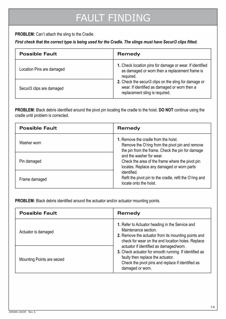
FAULT FINDINGPROBLEM: Can’t attach the sling to the Cradle.First check that the correct type is being used for the Cradle. The slings must have Securi3 clips fitted.
1. Check location pins for damage or wear. If identifiedas damaged or worn then a replacement frame isrequired.
2. Check the securi3 clips on the sling for damage orwear. If identified as damaged or worn then areplacement sling is required.
Possible Fault Remedy
Location Pins are damaged
Securi3 clips are damaged
PROBLEM: Black debris identified around the pivot pin locating the cradle to the hoist. DO NOT continue using thecradle until problem is corrected.
1. Remove the cradle from the hoist.Remove the O’ring from the pivot pin and removethe pin from the frame. Check the pin for damageand the washer for wear.Check the area of the frame where the pivot pinlocates. Replace any damaged or worn partsidentified.Refit the pivot pin to the cradle, refit the O’ring andlocate onto the hoist.
Possible Fault Remedy
Washer worn
Pin damaged
Frame damaged
PROBLEM: Black debris identified around the actuator and/or actuator mounting points.
1. Refer to Actuator heading in the Service andMaintenance section.
2. Remove the actuator from its mounting points andcheck for wear on the end location holes. Replaceactuator if identified as damaged/worn.
3. Check actuator for smooth running. If identified asfaulty then replace the actuator.Check the pivot pins and replace if identified asdamaged or worn.
Possible Fault Remedy
Actuator is damaged
Mounting Points are seized

15
294000.10039 Rev A
EXPLODED VIEW
16
294000.10039 Rev A
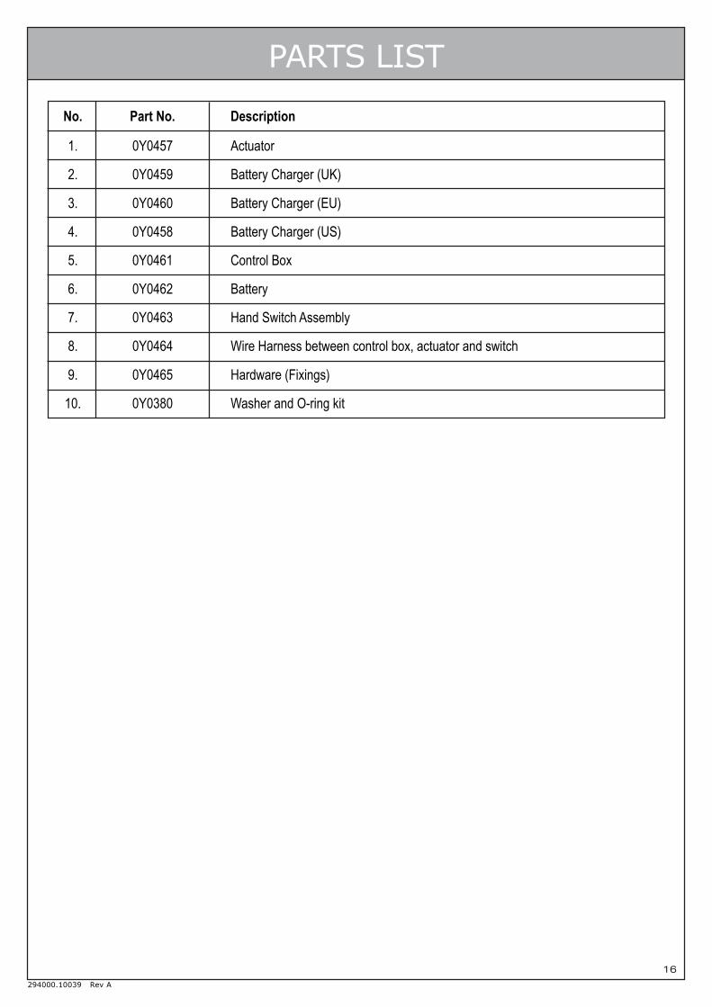
PARTS LIST
No. Part No. Description
1. 0Y0457 Actuator
2. 0Y0459 Battery Charger (UK)
3. 0Y0460 Battery Charger (EU)
4. 0Y0458 Battery Charger (US)
5. 0Y0461 Control Box
6. 0Y0462 Battery
7. 0Y0463 Hand Switch Assembly
8. 0Y0464 Wire Harness between control box, actuator and switch
9. 0Y0465 Hardware (Fixings)
10. 0Y0380 Washer and O-ring kit

17
294000.10039 Rev A
LOLER: Thorough Examination ReportLifting Operations and Lifting Equipment Regulations 1998 Schedule 1
Client Name & Address ______________________________________________________________
_______________________________________ Tel ______________________________________
Address of Examination _____________________________________________________________
Model ____________________ Serial No. ___________________ Date of Manu. ______________
Date of last Examination ________________ Safe Working Load ____________________________
Commissioning Examination ❏ Yes ❏ No Safe to Operate ❏ Yes ❏ No ❏ N/A
Periodic Examination ❏ Yes ❏ No
Interval of Examination ❏ 6 Months ❏ 12 Months ❏ Examination Scheme ❏ Exceptional
Safe to Operate ❏ Yes ❏ No ❏ N/A
Defective Parts (Immediate Attention):
Defects requiring rectification at a later date:
Part Number Description Defect Action Taken
Part Number Description Defect Action Taken Latest Date
Next examination due date ___________________________
Load test conducted according to ❏ BS 5827 ❏ BS EN ISO 10535 ❏ Other (state) ______________
Thorough examination carried out (Date) _______________________
Name of Examiner ___________________________ Job Title _______________________________
On behalf of (Company/Organisation) ___________________________________________________
Address __________________________________________________________________________
________________________________________________________
Signed _________________________ Signed on behalf ________________________________
Name & address ________________________________
______________________________________________
______________________________________________
______________________________________
Date of Report ___________________
18
294000.10039 Rev A
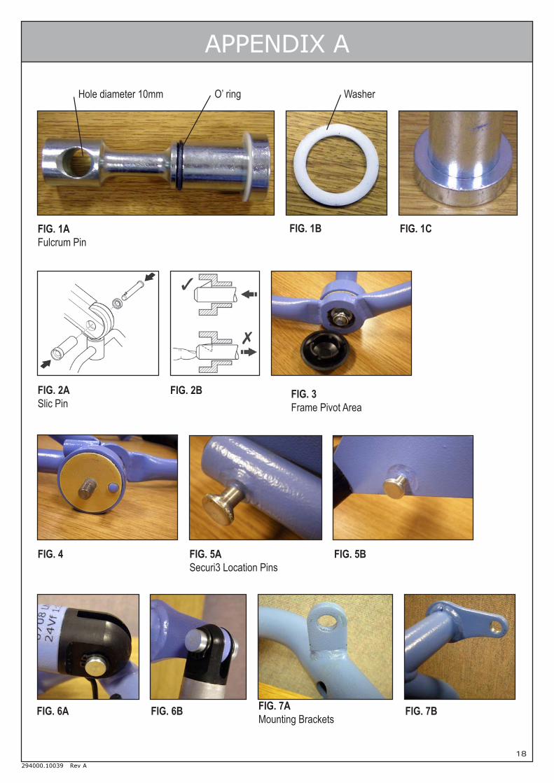
APPENDIX A
FIG. 1AFulcrum Pin
O’ ringHole diameter 10mm Washer
FIG. 2ASlic Pin
FIG. 3Frame Pivot Area
FIG. 1B FIG. 1C
FIG. 4
FIG. 2B
FIG. 5ASecuri3 Location Pins
FIG. 5B
FIG. 6A FIG. 6B FIG. 7AMounting Brackets
FIG. 7B

19
294000.10039 Rev A
APPENDIX A
FIG. 8AUpper Pin
FIG. 8BLower Pin
FIG. 9 FIG. 10
Contacts
FIG. 11 FIG. 12 FIG. 13
-ve Terminals+ve Terminal
-ve Terminals+ve Terminal
FIG. 14 FIG. 15 FIG. 16
FIG. 17 FIG. 18 FIG. 19

20
294000.10039 Rev A
APPENDIX A
FIG. 20 FIG. 21 FIG. 22 FIG. 23
FIG. 24 FIG. 25 FIG. 26
FIG. 27 FIG. 28 FIG. 29
FIG. 30 FIG. 31 FIG. 32
Stud Pivot WasherMechanical Stop Pin

21
294000.10039 Rev A
APPENDIX A
FIG. 33 FIG. 34 FIG. 35
FIG. 36 FIG. 37 FIG. 38
FIG. 39 FIG. 40 FIG. 41
FIG. 42 FIG. 43
Mechanical Stop Pin
-ve Terminals+ve Terminal

22
294000.10039 Rev A
APPENDIX A
FIG. 44 FIG. 45 FIG. 46A FIG. 46B
FIG. 47 FIG. 48
FIG. 49 FIG. 50 FIG. 51
FIG. 52 FIG. 53 FIG. 54
Remove backing to expose adhesive Membrane switch with adhesive exposed

23
294000.10039 Rev A
APPENDIX A
FIG. 55 FIG. 56 FIG. 57
FIG. 58 FIG. 59 FIG. 60
FIG. 61 FIG. 62 FIG. 63
FIG. 64
Apply Silicon Seal

24
294000.10039 Rev A
NOTES

294000.10039 Rev A
Joerns Healthcare LimitedHigh Street • Wollaston • Stourbridge • West Midlands • DY8 4PS • England
Tel +44(0)1384 44 66 22 • Fax +44(0)1384 44 66 [email protected] • www.joerns.co.uk


![INDEX [meanwell.com]meanwell.com/Upload/PDF/meanwell_LED.pdf · APC-8, APC-12, APC-16, APC-25, APC-35 3 APV-8E, APV-12E, APV-16E 4 APC-8E, APC-12E, APC-16E LP ... Over voltage protection](https://static.fdocuments.us/doc/165x107/5b619e107f8b9a40488c919f/index-apc-8-apc-12-apc-16-apc-25-apc-35-3-apv-8e-apv-12e-apv-16e-4.jpg)