OWNER’S OPERATOR AND MAINTENANCE · PDF fileU M M A R Y WARNING ... The bed frame must...
24
OWNER’S OPERATOR AND MAINTENANCE MANUAL microAIR 3500S ®
Transcript of OWNER’S OPERATOR AND MAINTENANCE · PDF fileU M M A R Y WARNING ... The bed frame must...
OWNER’S OPERATOR ANDMAINTENANCE MANUAL
microAIR 3500S®

2
WARNING
DO NOT OPERATE THIS EQUIPMENT WITHOUT FIRST READINGAND UNDERSTANDING THIS MANUAL. IF YOU ARE UNABLE
TO UNDERSTAND THE WARNINGS, CAUTIONS ANDINSTRUCTIONS, CONTACT A HEALTHCARE PROFESSIONAL,
DEALER OR TECHNICAL PERSONNEL IF APPLICABLE BEFOREATTEMPTING TO USE THIS EQUIPMENT. OTHERWISE INJURY OR
DAMAGE MAY RESULT.
SAVE THESE INSTRUCTIONS
WARNING
SPECIAL
NOTES
SPECIAL NOTES
WARNING/CAUTION notices used in this manual apply to hazards or unsafe practices whichcould result in personal injury or property damage.
NOTICETHE INFORMATION CONTAINED IN THIS DOCUMENT IS SUBJECT TO CHANGE WITHOUT NOTICE.
SPECIAL NOTES

3
TABLE OF CONTENTS
TABLE OF CONTENTS
TABLEOFCONTENTS
SAFETY SUMMARY ................................. 4
SPECIFICATIONS ..................................... 5
FEATURES .............................................. 6 QUICK REFERENCE - MICROAIR 3500 ....... 6
UNPACKING ............................................ 8 UNPACKING AND INSPECTION .................... 8
COMPONENTS SUPPLIED IN THE POWER UNIT PACKAGE .............................. 8
COMPONENTS SUPPLIED IN THE MATTRESS ASSEMBLY PACKAGE ............... 8
PROCEDURE 1 -SYSTEM PREPARATION ........................ 9BED FRAME PREPARATION .......................... 9
POWER UNIT INSTALLATION ........................ 9
PRE-ASSEMBLED MATTRESS INSTALLATION............................................... 9
AIR HOSE CONNECTION............................... 9
CPR PLUG INSTALLATION ............................. 9
THERAPY PAD INSTALLATION ..................... 10
POWER CORD ............................................ 10
SYSTEM OPERATION .................................. 10
PROCEDURE 2 - PATIENT SET UP ..... 11PATIENT SET UP .......................................... 11
PATIENT MANAGEMENT............................... 11
HEAD RAISED POSITION............................. 11
PATIENT TRANSFER FROM/TO A GURNEY................................................... 11
PATIENT TRANSFER FROM/TO A WHEELCHAIR .......................................... 11
ADJUSTABLE WIDTH SIDE RAILS ............... 11
PROCEDURE 3 -SERVICING/CLEANING/LAUNDRY ........ 12SERVICING .................................................... 12
CLEANING ..................................................... 12
LAUNDRY ...................................................... 13
PROCEDURE 4 -NON-STANDARD OPERATION .............. 14POWER UNIT RELOCATION ........................ 14
NARROW WIDTH BEDS................................ 14
MAINTENANCE ...................................... 15AIR FILTER REPLACEMENT ......................... 15
RECOMMENDED INSPECTION, MAINTENANCE AND TEST INTERVALS FOR MICROAIR 3500S LOW AIR LOSS THERAPY SYSTEMS ........ 16
INSPECTION ............................................ 17
OPTIONAL INSPECTION AND TEST REPORT MICROAIR 3500S SERIES LOW AIR LOSS THERAPY SYSTEMS ............ 17
INSPECTION AND TEST REPORT FOR SYSTEMS USED IN AN ACUTE CARE ENVIRONMENT MICROAIR 3500S SERIES LOW AIR LOSS THERAPY SYSTEMS ............ 18
TROUBLESHOOTING ........................... 19TROUBLESHOOTING ................................... 19
OPTIONAL EQUIPMENT/SPARE PARTS ....................................... 20OPTIONAL EQUIPMENT ............................... 20
SPARE PARTS .............................................. 20
APPENDIX .............................................. 21
SOURCES FOR GERMICIDAL CHEMICALS ................................................ 21
INFECTION CONTROL INFORMATION RESOURCES .............................................. 21
WARRANTY............................................ 23

4
SAFETY SUMMARY
SAFETY
SUMMARY
WARNING
CONTRAINDICATIONSAlways consult the patient’s physician before using the microAIR 3500S system. Certain medicalconditions preclude use of a low air loss mattress replacement system. e.g., unstable spinal cord,traction, etc.
INSTALLATIONThe microAIR 3500S must be installed on medical bed frames with side rails. After placing thepatient on the mattress, verify the side rails provide adequate protection for the patient. The siderails must be in the raised position, whenever a patient is on the bed.
Controls on the footboard may be obstructed by the Power Unit on a few bed frames. It may benecessary to relocate the Power Unit. See Non-Standard Operation Section for alternate PowerUnit locations.
Check that Air Hoses and Power Cord are clear of moving bed components before placing apatient on the bed. Operate all bed frame motorized functions through their full range of motionto verify there is no pulling, interference, or pinching.
The Therapy Pad is essential for skin moisture control. Do not place a patient directly on the Mat-tress without a Therapy Pad. The Therapy Pad protects the Mattress components from contami-nation.
SMOKING IN THE PATIENT ENVIRONMENTSmoking by the patient is not permitted and should be strongly discouraged. microAIR 3500Ssystems use room air for circulation through the mattress. Smoking by visitors in the bedroom willcontaminate the system. Visitor smoking is not permitted.
OXYGEN AND ANESTHESIA EQUIPMENTExplosion risk if used with flammable anesthetics. There is a possible fire hazard when used with anoxygen tent around the power unit or below mattress support level. A standard oxygen canula ornasal mask is acceptable.
ELECTRICALDisconnect the Power Cord from the wall outlet before performing any maintenance to thePower Unit. Refer servicing to qualified personnel only. Grounding reliability depends upon aproperly grounded wall outlet (three prongs). Always use the 18-foot hospital grade PowerCord provided with your product.
SERVICINGThe air filter element and mattress assembly are the only user-serviceable parts. Do not open thePower Unit. Refer all repair questions to Technical Customer Service at 1-407-328-1969. The systemmust be maintained, inspected and tested according to the schedule in the maintenance sec-tion of this manual to deliver consistent performance. If your system requires factory service, con-tact Customer Service for a Return Authorization number (RA). Package systems in the originalshipping box. Clean all system components before shipment. UNSANITARY SYSTEMS WILL BE RE-TURNED WITHOUT SERVICING.
SAFETY SUMMARY

5
SPECIFICATIONS
microAIR 3500S
AIR SACKS
Washable: YesWaterproof: YesQuantity: 3 sacksPressure Zones: 3Sack Seam Bonding: RF welded
PATIENT/MATTRESS INTERFACE
Vapor Permeable: YesMicroporous: NoLatex Components: None
FILTERS
Air Filter: YesNoise filter: Yes
WEIGHTS/CAPACITY
Patient Weight: 350 lb. maximumSystem Weight
Mattress: 32 lb.Power Unit: 20 lb.
AIR BLOWER
Service Life (est.): 24,000 hr.
DIMENSIONS
Mattress Width: 84 x 37-inches Standard width84 x 32-inches Narrow width
ELECTRICAL
Power: 115 VAC, 50/60 Hz, 2A (operating)
SAFETY
Listing Agency: Underwriters LaboratoriesListing Specification: UL 544Fire: California 106
MATTRESS SANITATION
Fluid Entrapment: No (seamless)Detergent. Resist: Yes
REGISTRATION
FDA Reg. No: K914674
PATENTS
US: 5,216,768
SPECIFICATIONS
SPECIFICATIONS

6
FEATURESQUICK REFERENCE - MICROAIR 35OOS
Control Panel Features (FIGURE 1)
1. Power Button - Press the button to turn on thePower Unit. Press the button again to turn off thePower Unit. The control panel power is always on,as indicated by the Stand By light.
2. Control Knob - Rotate the knob clockwise to in-crease mattress pressure.
3. Auto Firm - Press the Auto Firm Button to engageauto firm. The Mattress will become firm for nurs-ing procedures. An indicator lights to notify AutoFirm mode is on. A timer will cancel auto firm in 30Minutes. Should the nurse be called away, an un-attended patient will not be left on a firm surface.
4. Therapy - Press the Therapy Button to cancel AutoFirm mode.
Side Panel Features - Left (FIGURE 2)
1. Couplers - Three color coded quick connect fit-tings that connect to the hoses. Push in the slid-ing collar release and insert the hose coupler untilthe collar snaps back to it’s original position.
FEATURES
Power Button
Control Knob
Auto Firm
Therapy
FEATURES
FIGURE 1 - CONTROL PANEL FEATURES
FIGURE 2 - SIDE PANEL FEATURES - LEFT

7
FEATURES
Rear Panel Features (FIGURE 3)
1. Power Connector - Push in the cord plug to in-stall the Power Cord. Use only the 18 foot hospitalgrade cord to insure safety ground.
2. Filter Door - Open the Filter Door to change theAir Filter. Rotate counterclockwise to remove.
3. Mounting Brackets - Narrow and wide swing-outBrackets fit most bed footboards.
4. Range Switch - Inside the filter compartment is aswitch to control the patient weight range. High for150-350 lbs. Low for 0-180 lbs. The 3500S hasenough power to produce excess mattress firm-ness for small patients. The Range Switch is hid-den in the filter compartment to prevent unautho-rized power adjustment.
Mounting Brackets
Range Switch
Filter Door
Power Connector
FEATURES
FIGURE 3 - REAR PANEL FEATURES

8
UNPACKING AND INSPECTIONEach microAIR 3500S is shipped in two (2) boxes.One contains the Power Unit. The other contains theMattress Assembly. Verify that no components aredamaged or missing. Report any damage to the trans-port carrier immediately.
COMPONENTS SUPPLIED IN THEPOWER UNIT PACKAGE1 Power Unit1 Operation and Maintenance Manual1 Power Cord
COMPONENTS SUPPLIED IN THEMATTRESS ASSEMBLY PACKAGE1 Mattress Assembly with Air Hoses - Red, Blue,
and Green1 Nylon Duffel Bag
UNPACKING
UNPACKING
UNPACKING
9
SYSTEMPREPARATION
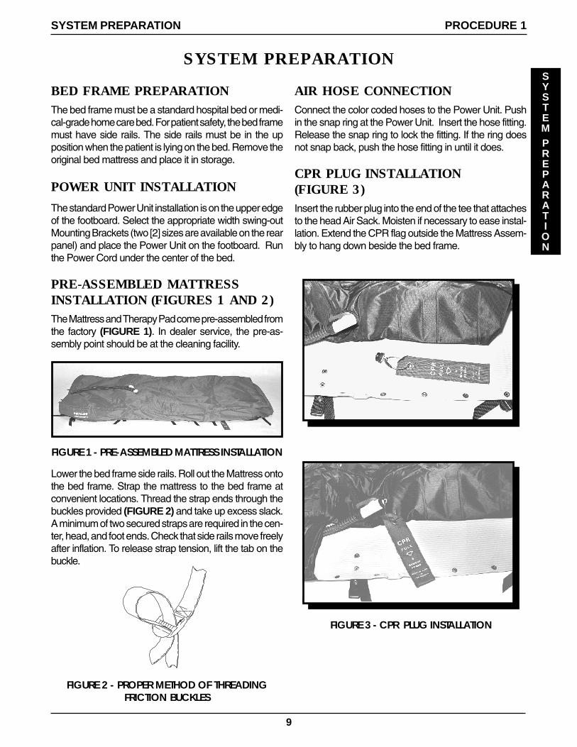
FIGURE 2 - PROPER METHOD OF THREADINGFRICTION BUCKLES
AIR HOSE CONNECTIONConnect the color coded hoses to the Power Unit. Pushin the snap ring at the Power Unit. Insert the hose fitting.Release the snap ring to lock the fitting. If the ring doesnot snap back, push the hose fitting in until it does.
CPR PLUG INSTALLATION(FIGURE 3)Insert the rubber plug into the end of the tee that attachesto the head Air Sack. Moisten if necessary to ease instal-lation. Extend the CPR flag outside the Mattress Assem-bly to hang down beside the bed frame.
BED FRAME PREPARATIONThe bed frame must be a standard hospital bed or medi-cal-grade home care bed. For patient safety, the bed framemust have side rails. The side rails must be in the upposition when the patient is lying on the bed. Remove theoriginal bed mattress and place it in storage.
POWER UNIT INSTALLATION
The standard Power Unit installation is on the upper edgeof the footboard. Select the appropriate width swing-outMounting Brackets (two [2] sizes are available on the rearpanel) and place the Power Unit on the footboard. Runthe Power Cord under the center of the bed.
PRE-ASSEMBLED MATTRESSINSTALLATION (FIGURES 1 AND 2)The Mattress and Therapy Pad come pre-assembled fromthe factory (FIGURE 1). In dealer service, the pre-as-sembly point should be at the cleaning facility.
PROCEDURE 1SYSTEM PREPARATION
SYSTEM PREPARATION
FIGURE 1 - PRE-ASSEMBLED MATTRESS INSTALLATION
Lower the bed frame side rails. Roll out the Mattress ontothe bed frame. Strap the mattress to the bed frame atconvenient locations. Thread the strap ends through thebuckles provided (FIGURE 2) and take up excess slack.A minimum of two secured straps are required in the cen-ter, head, and foot ends. Check that side rails move freelyafter inflation. To release strap tension, lift the tab on thebuckle.
FIGURE 3 - CPR PLUG INSTALLATION

10
SYSTEMPREPARATION
PROCEDURE 1 SYSTEM PREPARATION
THERAPY PAD INSTALLATIONStarting at the foot end of the bed, lay the Therapy Pad(quilted side down) on top of the Mattress. Connect theTherapy Pad snaps to the corresponding snaps on thestraps located on the Mattress (near the bed frame). Apatient should not be placed directly on the Mattress with-out a Therapy Pad. A loose (non fitted) cotton sheet be-tween the patient and Therapy Pad is optional. A tightlyfitted cotton sheet may increase skin friction and shear.
POWER CORDPlug the Power Cord into a wall outlet. Verify that Air Hosesand Power Cord are clear of moving bed components.Operate all bed motorized functions through their fullrange. Check for pulling, interference or pinching, andcorrect any problems.
SYSTEM OPERATIONPress the Power Button to start the Power Unit. The Mat-tress will start to fill slowly. Press the Auto Firm Button toinflate the Mattress quickly. Press the Therapy Buttonwhen inflated. The foot air sack section will inflate slowly.If the Mattress does not inflate, refer to the TROUBLE-SHOOTING section of this manual.

11
PATIENT
SETUP
PROCEDURE 2
PATIENT MANAGEMENTAfter placing the patient, make certain no objects will fallunder the patient, such as feeding tubes, IV’s etc. Use aregular pillow to help support and stabilize the patient’shead. Make sure the patient’s limbs assume natural posi-tions without pinching. Use pillows, foam or sheepskinappliances as required to cushion potential body to bodycontact areas.
HEAD RAISED POSITIONWhen elevating the head of the bed, elevate the kneesection first. The Therapy Pad is slippery to minimize skinfriction. Head elevation without knee elevation may causethe patient to slide toward the foot of the bed.
The head of the bed should be maintained at the lowestdegree of elevation consistent with medical conditions(AHCPR Pub. 92-0047, P.24). The lowest skin pressureis maintained with 0° to 20° head raise angle. Anglesabove 30° place more body weight over the seat area,reducing pressure relief. Instruct the care-giver to avoidhead angles over 30° for extended periods, unless medi-cally necessary (US Department of Health and HumanServices publication No. 92-0048).
PATIENT TRANSFER FROM/TO AGURNEYPress Auto Firm to achieve maximum mattress pressure.Raise or lower the bed to match the gurney height. In twoto three minutes the Mattress will become very firm sothe patient can be slid onto the gurney. Always securethe bed and gurney during patient transfers.Press therapyto return mattress pressure to the original setting.
PATIENT TRANSFER FROM/TO AWHEELCHAIRTurn “OFF” the unit to deflate the Mattress so the patientis on the same level as the wheelchair. After transferringto a 3500s, have the patient lie on their back and raise thebed side rails to the safety position. Press the Power But-ton “ON”. Press the Auto Firm Button and wait until theMattress is inflated. Press the Therapy Button to returnthe patient to floatation.
ADJUSTABLE WIDTH SIDE RAILSSome home care beds have adjustable width side rails.Set the side rail width so the rails touch the Mattress.Avoid a gap between the mattress and side rail.
FIGURE 1 - PATIENT SETUPReach in under the patients body until the hand isdirectly below the spinal area. Place the heel of thehand on the mat assembly and raise the thumb. Ifthe patient is too high, the thumb will not touch thepatient’s body. If the patient is too low, you will not beable to raise the thumb. Adjust the control Knob untilthe proper floatation level is achieved. Wait at leastthree minutes between each adjustment for the pres-sure to stabilize.
6. Raise the bed frame knee section and head section30 degrees. Observe if the patient bottoms out againstthe frame. If so, the Control Knob pressure is adjustedtoo low. Raise the pressure and retest the patient flo-tation level with the bed frame lowered.
7. Check the Auto Firm function for proper mattress firm-ness.
8. The foot air sack section will always be soft to reducepressure in the heel section.
PATIENT SETUP
PATIENT SETUP
PATIENT SETUP (FIGURE 1)1. Install system on a medical bed frame with side rails
and inflate.
2. Check patient weight. If patient weight is between 0-180lbs., set the power Range Switch inside the filterdoor, to LOW range. If between 150 - 350lbs., set theswitch to HIGH range (the blower runs faster whenyou switch the toggle to HIGH). Adjust pressure Con-trol Knob fully clockwise. Push the Therapy Button.
3. Ask the nursing staff to place the patient on the bed.Center the patient on the bed from side-to-side andhead-to-foot. Use a regular pillow under the head forcomfort and to control head position. Special posi-tioning may be required with contracted patients toprovide comfortable positions.
4. Gradually lower (counterclockwise) the control knobevery three (3) minutes until approximately 3-inchesof the patients body is immersed into the mattresstop surface. The goal is to achieve flotation of thebody for minimum skin contact pressure.
5. After stabilization, insert your hand as if shaking handswith someone with your thumb pointing up, betweenthe head and seat air sack.

12
SERVICING
Dress Standards
Standard clothing consists of street clothes, lab coat, andtwo pairs of gloves (one pair is a spare). Gloves shouldbe worn when touching the patient, dressings or bodyfluids. Proper procedures for donning and removal ofprotective clothing should be observed.
Unit Setup
The 3500S system is made patient-ready at the dealer-ship before delivery to the installation site. The Mattressis pre-assembled and Power Unit tested according to themaintenance schedule.
Ask the caregiver or nursing staff what isolation precau-tions are required when performing adjustments with thepatient on the bed. Typically, if protective clothing is re-quired, the institution will provide it to all health care work-ers.
Routine Maintenance
Disposable gloves are worn on all maintenance visits.They are disposed of after visiting each patient. Handwashing is required before and after gloves are worn.
Filter replacement should be scheduled very 9 weeks or1,500 hours. For light soil, the Therapy Pad can be cleanedby topical wipe down with a pH balanced soap and watersolution normally used to wash the patient. Rinse withwater. If soiled, the Therapy Pad should be laundered.
Collecting
When collecting the 3500S system, put on gloves andother protective equipment if required. Turn “ON” thePower Unit. Check the underside of the Therapy Padand mattress folds for sharps (e.g. scissors, needles,etc.). Discard before proceeding. Examine the sur-face of the Power Unit, Therapy Pad and MattressAssembly components for visible blood or body fluids.If blood is present, decontaminate. Insure that bed-ding is bagged and labeled before removal from thepatient site.
If blood is not present, remove excess soil from theTherapy Pad with paper towels. Dispose of towels ac-cording to institutional policy. Wipe the top (patient) sur-face down with a dilute detergent solution, quaternarycleaner disinfectant, or other germicidal detergent solu-tion. Turn “OFF” the Power Unit. Clean any soiled areas
SERVICE
of the Power Unit and Hose Fittings with the detergentsolution.
Disconnect hoses from the Power Unit and allow air tovent from the Mattress. Gently roll up the Mattress withminimal agitation. Check the Therapy Pad surface is in-side the roll. Place the used bedding in a laundry trans-port bag, appropriately labeled. Verify the bag is sealedbefore removing it from the room. Never place usedbedding or soiled components in the microAIR duf-fel bag because it will become contaminated. Theused gloves should be disposed of properly according toinstitutional policy. Move the entire microAIR system fromthe patient’s room to the transport vehicle.
SERVICING/CLEANING/LAUNDRY
CLEANINGmicroAIR equipment should be inspected. Any itemthat is visibly soiled with the patient’s blood or otherbody fluids should be properly cleaned.
Recommended Cleaning Materials
Disinfectant chemicals should be EPA registered hos-pital grade type with effectiveness claims for destruc-tion of harmful microorganisms. Hospital grade disin-fectant chemicals are available from many manufac-turers. Use the manufacturer’s recommended dilution.Never mix different chemicals together in the samecontainer.
Phenolic disinfectants supplied in highly concentratedform are effective in decontaminating blood spills. Qua-ternary cleaner disinfectants are usually capable ofcleaning, deodorizing and disinfecting in a single op-eration. They are especially suitable for cleaning equip-ment at the patient site where low level disinfection orodor control is needed. Laundry disinfectant presoakscan be either phenol or quaternary chemicals.
Cleaning At the Patient Site
Whenever the Therapy Pad is visibly soiled, clean witha pH balanced soap and water solution normally usedto wash the patient. Rinse with water. Cleaning withthe patient on the bed is not recommended.
PROCEDURE 3
SERVICING/CLEANING/LAUNDRY
SERVICING
CLEANING
LAUNDRY

13
Cleaning and Decontaminating Spills of BodyFluids
Cleaning blood spills must be done with protective cloth-ing, due to the risk of contracting HIV and hepatitis. Glovesmust be worn during cleanup. Hands should be washedthoroughly after completion. First, all visible soil should beremoved with disposable paper towels. Next, the areashould be scrubbed with freshly prepared phenolic deter-gent disinfectant solution. In general, chemical germi-cides that are EPA registered for use as hospital disinfec-tants can be used to decontaminate blood spills.
Field Cleaning of microAIR Power Units
Turn “OFF” the Power Unit and remove the Power Cord.Wipe down the Power Unit with a quaternary disinfectantsolution. A nylon brush may be useful since crevices canharbor microorganisms. All treated surfaces should beallowed to air dry before connecting the Power Cord andrestarting the system.
LAUNDRYLaundry workers should treat all soiled bedding as if itwere contaminated with pathogenic microorganisms.Laundry workers should wear gloves, gowns and addi-tional protective equipment as needed. Separate soiledand clean bedding areas should be designated so thatcross contamination cannot occur. Soiled bedding shouldnot be placed on the floor. Space should be provided forsorting, folding, bagging of clean bedding and to reas-semble the Mattress.
Mattress Disassembly
Place the Mattress Assembly on a suitable work table.Remove the Therapy Pad. Follow the laundry procedurefor Therapy Pad. Wipe down the Mattress and air hoseassembly with a properly diluted solution of quaternarycleaner disinfectant and air dry.
SERVICING/CLEANING/LAUNDRY
Presoak
Remove Therapy Pad to be laundered from the bag. Placein a washing machine. Fill the tub with warm water (below120°F). Add presoak disinfectant. Follow manufacturer’sdilution directions.
Washing Cycle
Place laundry into a washing machine. Do not overloadthe machine. Wash Therapy Pads separate from AirSacks. Wash with warm water (120°F max.) and deter-gent. Follow manufacturer’s directions. Do not use con-centrated bleach because it may damage the fabric coat-ing.
Machine Drying Method
Laundry workers should always wash their hands beforeworking with clean bedding. Dry Therapy Pads below120°F in a clothes dryer with accurate controls. (High airtemperatures will damage the fabrics and void the Invacarewarranty.)
Mattress Assembly (FIGURE 1)
Place the Mat Assembly on a clean work table. Snapthree Air Sacks to the Mat along the far left side (viewedfrom foot end). Note the two snaps closer together at thejunction of the foot and seat section Air Sacks. Attachhoses and secure retainer velcro straps. The short hosegoes to the foot, middle hose to the seat, and the longhose with CPR flag to the head Air Sacks. Snap the otherside of the Air Sacks to the Mat. The CPR flag must ex-tend outside the assembly. The hoses should extend outthe foot end on the left side. Connect the hoses to thePower Unit and turn on power. Check for abnormal leaksor misalignment. Cover the Mattress with the TherapyPad and snap in place. Roll up the mattress and store inthe duffel bag.
CLEANING
SERVICING
FIGURE 1 - MATTRESS ASSEMBLY
PROCEDURE 3
CLEANING
LAUNDRY

14
The majority of installations are successfully handledusing the procedures detailed in this manual. When adifficult situation arises, call your Technical customerservice representative for assistance. 407-328-1969
POWER UNIT RELOCATIONSome bed frames have controls that are obstructedby the standard Power Unit installation. It will be nec-essary to relocate the Power Unit if essential controlfunctions are not duplicated elsewhere on the bed.
The Power Unit can be installed on the headboard, anight stand, or on the floor using optional extendedhose sets. Call your Invacare customer service repre-sentative.
NARROW WIDTH BEDS
Invacare offers an optional narrow width mattress as-sembly for use with 32-inch wide ICU type bed frames.Whatever the application, the side rails should touchthe Mattress.
NON-STANDARD OPERATIONNONSTANDRADOPERATION
NON-STANDARD OPERATIONPROCEDURE 4

15
The microAIR 3500S system is equipped with an AirFilter. The filter can be changed without moving thepatient or turning “OFF” the unit. Regular servicingwill insure the blower operates at maximum power.
AIR FILTER REPLACEMENT(FIGURE 1)The Air Filter should be changed every 1,500 hours (9weeks) of continuous operation, or before the nextpatient is placed on the system. If the filter becomesexcessively dirty, the system pressure will decrease.
The Air Filter is located behind the Filter Door (insidethe Power Unit). The element is replaced as follows:
1. Open Filter Door by counterclockwise rotation.
2. Remove the used filter element and discard.
3. Install a new Air Filter element.
4. Close the Filter Door by clockwise rotation.
MAINTENANCE
MAINTENANCE
FIGURE 1 - AIR FILTER REPLACEMENT
MAINTENANCE

16
RECOMMENDED INSPECTION, MAINTENANCE ANDTEST INTERVALS FOR MICROAIR 3500S
LOW AIR LOSS THERAPY SYSTEMS
The following procedures are to be performed by the designated service organization, dealer, orinstitutional Biomed department:
Time Interval Description of Recommended Activity
1,500 hours - Remove and replace Air Filter cartridge(9 weeks of - Inspect Air Hose connections & Mattress Assembly functioncontinuous - Inspect Power Unit and Power Cordoperation)
After - Perform general physical inspection of Mattress Assembly, decontamination Hoses, Power Unit and Power Cord.
of system - Perform electrical line leakage test.- Perform electrical ground integrity test.
Annually, or after - Perform general physical inspection of Mattress Assembly, 8,000 hours of Hoses, Power Unit and Power Cord. operation - Perform electrical line leakage test (for acute care hospitals)
- Perform electrical ground integrity test (for acute care hospitals)- Remove and replace Air Filter cartridge - Check for loose hardware or physical damage which might affect operation or safety
MAINTENANCE
MAINTENANCE

17
OPTIONAL INSPECTION AND TEST REPORTMICROAIR 3500S SERIES
LOW AIR LOSS THERAPY SYSTEMS
System serial # __________________ Date:_______________
Service person: ______________________________________________________________Print Name
Service performed: ____ 1,500 hour ____ Post-decontamination
____ Repair ____ Annual or 8000 hour
Components replaced: ____ Air Filter
______________________ Other (specify)
______________________ Other (specify)
PHYSICAL INSPECTION CHECKLIST
Therapy Pad
Mat Assembly
Air Sacks
CPR Flag
Air Hoses
Power Unit
Power Cord
Mounting Hardware
Control Panel
Markings & Labels
Other
Item ��� OK Bad Comments
INSPECTION
INSPECTION

18
INSPECTION AND TEST REPORT FOR SYSTEMSUSED IN AN ACUTE CARE ENVIRONMENT
MICROAIR 3500S SERIESLOW AIR LOSS THERAPY SYSTEMS
ELECTRICAL TEST CHECKLIST
Item Parameter Requirements
Electrical leakage: __________ µµµµµa No reading shall Normal __________ µµµµµa exceed 100 Reverse __________ µµµµµa microamps ( a) Ground connected
Ground resistance Resistance shallfrom plug to Power not exceed 100Unit chassis: __________ milliohms milliohms
This unit has: ____ passed ___ failed the above inspections. If failed, the following repairs corrections are required
_________________________________________________________________________________
_________________________________________________________________________________
_________________________________________________________________________________
_________________________________________________________________________________
_________________________________________________________________________________
_________________________________________________________________________________
_________________________________________________________________________________
I certify that this unit conforms to the inspection and test criteria, and that scheduled maintenance has been performed as indicated.
I certify that this unit is validated for service.
_____________________________________ _______________ Signature of service person Date
INSPECTION
INSPECTION

19
If you experience operational problems with the microAIR 3500S, the following check points may be helpful:
PROBLEM WHAT TO CHECK FOR
No inflation; blower Check the Power Switch is ON and the Power Cord is plugged intocannot be heard a 3 prong receptacle. If the Power Switch does not light, check the
electrical outlet for line voltage.
One Air Sack Check the Sack for cuts, tears or material separation. Check thedoesn’t fully inflate hose couplings are fully latched to the Power Unit and Air Sack.or is totally deflated Check Hose for leaks.
All Air Sacks are Increase the weight setting. Listen and feel for air leaks in thetoo soft system. Follow the setup instructions on page 10. The Air filter
may require replacement. Refer to the MAINTENANCE Procedureof this manual.
All Air Sacks Check for air flow from the Power Unit. Check Hose connections.are uninflated; theblower is running
TROUBLESHOOTING
TROUBLESHOOTING
TROUBLESHOOTING

20
Contact your Invacare customer service representa-tive for supplies and applications assistance.
Air Supply Hoses - Hoses can be supplied for any length.
Incontinence Pads - microAIR incontinence pads arebreathable pads used when patients are constantlysoiling the bed. The pads are laid on top of the TherapyPad with the white surface up and the blue surfacedown. The patient is placed on the white surface.Breathable pads are different from standard, plasticlined products, because they do not interfere with theskin moisture removal capability of the system.
Narrow Mattress Assembly - This Mattress is spe-cifically designed for use with narrow, intensive carebeds.
OPTIONAL EQUIPMENTOPTIONALEQUIPMENT
OPTIONAL EQUIPMENT / SPARE PARTS
SPARE
PARTS
OPTIONAL EQUIPMENT
SPARE PARTS
A list of available parts is shown below. Contact yourInvacare customer representative for supplies andservice.
● Air Filter
● Therapy Pad - Standard or narrow width
● Air Sacks - 28-inches
● Mat Assembly
● Air Supply Hoses - standard lengths, color coded:Yellow, Blue, and Green
● Nylon Duffel Bag (for Mattress Assembly)
● Operation and Maintenance Manual
● Power Cord
● CPR Flag/Plug assembly
● Power Unit
SPARE PARTS

21
SOURCES FOR GERMICIDAL CHEMICALS
The following companies offer germicidal chemicals through distributors:
Probrands, division of Record and Coleman(Lysol Brand Disinfectants)..... 800-677-9218
Convatec, division of Bristol Myers, Squibb (LpHse, TBQ).......................... 800-325-8005
MADA Equipment Company (MadaCide).................................................... 800-526-6370
Note: Lysol, MadaCide, LpHse, and TBQ are registered trademarks.
INFECTION CONTROL INFORMATION RESOURCES
The following resources may be used for additional information:
For US Government documents:National Technical Information Service............................................ 703-487-4650The US Government Printing Office.................................................. 202-512-1803
For HIV and HBV information:CDC AIDS Information Clearinghouse.............................................. 800-458-5231
For CDC documents(Centers for Disease Control) by FAX......................... 404-332-4565
For the OSHA Bloodborne Pathogen Standard........................................... 202-219-4667
For information regarding chemical germicides and disinfectants:EPA(Environmental Protection Agency), Antimicrobial Branch.......... 202-260-7751
APPENDIX
APPENDIX
APPENDIX

22
NOTES
NOTES
NOTES

23
WARRANTY
LIMITED PRODUCT WARRANTY
Invacare warrants the microAIR 3500S Power Units to be free of defects in material and workman-ship for two (2) years from the date of initial shipment to the Original Purchaser (Pur-chaser). No warranty shall apply if the goods have been damaged by accident, abuse,misuse, misapplication or as a result of unauthorized or improper service or modifications.Invacare’s liability under this warranty, and Purchaser’s exclusive remedy, is limited to thecost of materials to repair the defective goods, or to their replacement, and in no eventshall exceed the purchase price.
Replacement or repair of defective Power Units under this warranty will be made only uponprepaid return of the defective Power Unit to Invacare. Purchaser shall receive prior return autho-rization (RA number) and instructions from Invacare before returning goods. Upon receipt of goodsunder warranty, Invacare will notify Purchaser of the extent of replacement or repair that Invacarewill supply under warranty, which shall be conclusive of Invacare’s liability.
Invacare warrants Soft Goods for the above referenced microAIR systems to be free of defects inmaterial and workmanship for one half year (180 days) from the date of initial shipment to thePurchaser. Soft Goods means all system components excluding the Power Unit. No warranty shallapply if the goods have been damaged by accident, abuse, misuse, misapplication or becauseof unauthorized or improper service or modifications. Misuse includes laundering and cleaning ofSoft Goods using chemicals that attack the materials. Invacare’s liability under this warranty, andPurchaser’s exclusive remedy, is limited to the cost of materials to repair the defective goods, orto their replacement, and in no event shall exceed the purchase price.
Replacement or repair of defective Soft Goods under this warranty will be made only upon pre-paid return of the defective goods to Invacare. Purchaser shall receive prior return authorization(RA number) and instructions from Invacare before returning goods. Upon receipt of goods un-der warranty, Invacare will notify Purchaser of the extent of replacement or repair that Invacarewill supply under warranty, which shall be conclusive of Invacare’s liability.
If your microAIR system requires factory service, always ship in the original shipping box and pack-ing. Thoroughly clean all system components before shipment. Unsanitary systems will be re-turned without servicing. Invacare is not responsible for incidental or consequential damagesresulting from the breech of any expressed or implied warranty, including damage to propertyand, to the extent permitted by law, damages for personal injury. The warranty contained hereinis in lieu of all other warranties, expressed or implied, including implied warranties of merchant-ability and fitness for a particular purpose. No statement of any Invacare representative shallextend Invacare’s liability as herein established or limited.
WARRANTY
WARRANTY

INVACARE CORPORATIONONE INVACARE WAY ●●●●● Elyria, OH 44036-2125
Customer Service 1-800-333-6900 ● ● ● ● ● Technical Support - 1-407-328-1969
Form No: 98 - 148 Part No. 9692006 (Rev 4/98) Printed in U.S.A.