OWNER’S OPERATION & PARTS MANUAL - Bad Boy …€™S OPERATION & PARTS MANUAL ... (gearbox output...
28
OWNER’S OPERATION & PARTS MANUAL 6-23-2015
Transcript of OWNER’S OPERATION & PARTS MANUAL - Bad Boy …€™S OPERATION & PARTS MANUAL ... (gearbox output...
OWNER’S OPERATION& PARTS MANUAL
6-23-2015

PAGE 2
TO THE DEALER:
Assembly, initial lubrication, and verification of proper installation of this product is the responsibility of the
Bad Boy Cutter dealer. Be familiar with the safety rules and instructions found in this manual. Ensure all items
on the Dealer’s Pre-Delivery and Delivery Checklists in this manual are completed before releasing the cutter to
the new owner. This cutter is sent from the factory without gearbox oil.
TO THE OWNER:Read this manual before operating your Bad Boy Cutter and require this of any other person that is to operate
this equipment. Although this cutter has been engineered with safety and reliability as the foremost concerns,
there is no substitute for an informed and cautious operator. This manual should be viewed as a part of
the equipment itself. If this manual is lost, destroyed, or otherwise rendered unreadable, obtain a duplicate
immediately. A duplicate can be obtained online at www.badboymowers.com.
As with all machinery, this cutter requires periodic maintenance and should be kept free of debris buildup.
Proper care will ensure many years of dependable service. Replacement parts should only be obtained from
your Bad Boy Cutter dealer or through the website referenced above. Failure to utilize approved parts can be
dangerous and will void the warranty.
LEA EL INSTRUCTIVO!Si no lee Ingles, pida ayuda a alguien que si lo lea para que le traduzca las medidas de seguridad.
Three terms are utilized throughout this manual and are present on the cutter’s safety decals:
DANGER, WARNING, and CAUTION.
DANGER: Indicates a hazardous situation that, if not avoided will result in death or serious injury.
WARNING: Indicates a hazardous situation that, if not avoided, could result in death or serious injury.
CAUTION: Indicates a hazardous situation that, if not avoided, could result in minor or moderate injury.
In order to better draw attention to these important safety messages,
the above terms are accompanied with the following pictorial:
PAGE 3
TABLE OF CONTENTS
SPECIFICATIONS .............................................................................................. 4
SAFETY RULES ................................................................................................ 5
GENERAL INFORMATION ................................................................................. 8
OPERATION ...................................................................................................... 8
OWNER SERVICE ............................................................................................13
TROUBLESHOOTING .......................................................................................18
CUTTER ASSEMBLY AND PART LIST .............................................................19
FASTENER TORQUE CHART ...........................................................................24
DEALER’S CHECKLISTS ................................................................................. 25
PRODUCT WARRANTY .................................................................................. 26

PAGE 4
SPECIFICATIONSCategory 5´ Bad Boy CutterGear Box 50hp heavy duty Omni RC51Gear box mount 3/8˝ steel; completely surrounded by interlocking ‘H’ supportsDeck Thickness 1 Piece, 11 Gauge solid welded Skirt Thickness 3/16˝ steelUnder-decking support 1/4˝ x 6-1/2˝Skid Shoes 1/2˝ x 2˝ x 32˝ (24˝ of ground contact)Deck Support Vertical interlocking, welded ‘H’ frameLift attachment brackets 1/2˝ solid welded Tail-wheel arms 1/2˝ x 2-1/2˝ designed to withstand rear tractor wheel lift offTail-wheel 4˝ x 15˝ puncture resistant w/ double bolt adjustmentStump Jumper 15 splined. Heavy-duty, reinforced round stump jumper Warranty 2 year limitedWeight 650 lbs Length (including tail-wheel) 100˝Total Width 63-1/2˝Overall height 40˝Deck Height 7˝Cut Range 2˝–10˝PTO Drive Shaft Series 5 Shear Bolt or Series 5 Slip ClutchBlades 1/2˝ x 3˝Tractor Range 25-65 HP Cutting Capacity 2˝ diameterBlade tip speed 16,500 feet/minute3-Point Hitch Category 1Blade Spindle 1Tractor PTO RPM 540

PAGE 5
SAFETY RULESTRAINING
■ Safety instructions are important!! While these instructions and rules may seem lengthy or redundant,
they are presented for your safety. Almost all accidents arising from the use of equipment such as
this that has resulted in injury or death would have been avoided had instructions such as these been
adhered to.
■ If you do not understand any part of this manual, contact your dealer for assistance.
■ Dangerous situations can arise quickly. Know your controls and how to stop the engine and attachment
quickly in an emergency. Fractions of a second can be extremely important.
■ Do not allow anyone to operate the equipment without first requiring them to read this manual and
giving proper instruction.
■ Never allow children (< 16 years of age) or untrained persons to operate the equipment.
PREPARATION
■ Check that all hardware is properly installed.
■ Loose clothing can become caught in moving parts. Entanglement with the rotating PTO shaft is the #1
cause of death and injury with equipment such as this. Always wear relatively tight and belted clothing
to reduce this risk.
■ Wear sturdy, rough-soled work shoes and protective equipment for eyes, hair, hands, hearing, and
head. Wear a respirator or filter mask where appropriate.
■ Make sure the cutter is properly secured, adjusted, lubricated, and in good operating condition.
■ Make sure spring-activated locking pin slides freely and is seated firmly in tractor PTO spline groove.
■ Connect PTO driveline directly to power unit PTO shaft. Never use adapter sleeves or adapter shafts.
Adapters can cause driveline failures.
■ Before starting power unit, check driveline guards for damage. Do not operate without replacing any
damaged guards. Ensure the guards rotate freely on the driveline. If they do not, repair or replace
bearings before operating the cutter.
■ Tractor must be equipped with Roll-Over Protective Structure (ROPS) or ROPS cab and seat belt.
ALWAYS keep seat belt securely fastened. Falling off the tractor can, and does, result in death. Keep
fold-able ROPS system in ‘locked up’ position at all times.
■ Inspect guards before use. Replace if damaged. DO NOT OPERATE the cutter without guards in place.
■ Accumulation of debris can present hazards. Remove accumulated debris from the cutter and tractor
before use.
■ Make sure all safety decals are installed and free from damage. Replace if damaged.
■ A minimum of 20% of tractor and equipment weight must be on the tractor front wheels when
attachments are in transport position. Without this weight, front tractor wheels could raise up resulting

PAGE 6
in loss of steering. The weight may be attained with front wheel weights, ballast in tires or front tractor
weights. Weigh the tractor and equipment; do not estimate.
■ Inspect and clear the area of stones, branches, or other hard objects that might be thrown, causing
injury or damage.
OPERATION
■ Do not allow bystanders in the area when operating, attaching, removing, assembling, or servicing the
cutter.
■ This machine is equipped with front and rear guards. DO NOT operate the machine without the guards
in place.
■ Never direct discharge toward people, animals, or property.
■ Do not operate or transport equipment while under the influence of alcohol or drugs.
■ Operate only in daylight or good artificial light.
■ Keep hands, feet, hair, and clothing away from equipment while engine is running. Stay clear of all
moving parts.
■ Always comply with all state and local lighting and marking requirements.
■ NEVER ALLOW RIDERS ON POWER UNIT OR CUTTER!
■ Always sit in the tractor seat when operating controls or starting engine. Securely fasten seat belt,
place transmission in neutral, engage brake, and ensure all other controls are disengaged before
starting tractor engine.
■ Operate tractor PTO at 540 RPM. Do not exceed.
■ Do not operate PTO during transport.
■ Look down and to the rear and make sure area is clear of people, animals, property, or foreign objects
before operating in reverse. Children often do not understand the severity of the potential danger. A
major portion of mower/cutter accidents involve children being run over during reverse operation of
the mower/cutter.
■ Do not operate or transport on steep slopes.
■ Do not stop, start, or change directions suddenly on slopes.
■ Use extreme care and reduce ground speed on slopes and rough terrain.
■ Watch for hidden hazards on the terrain during operation.
■ Stop tractor unit and equipment immediately upon striking an obstruction. Turn off engine, remove
key, inspect, and repair any damage before operation resumes.
■ Leak down or failure of mechanical or hydraulic system can cause equipment to drop.
■ Make certain all movement of equipment components has stopped before exiting the tractor.
MAINTENANCE
■ Before performing any service or maintenance disconnect driveline from tractor PTO.
■ Before working underneath the equipment, disconnect driveline, raise cutter, and block cutter securely.
Hydraulic system leak down and failure of mechanical or hydraulic system can cause equipment to drop.

PAGE 7
■ Do not allow bystanders in the area when operating, attaching, removing, assembling, or servicing
equipment.
■ Keep all persons away from operator control area while performing adjustments, service, or
maintenance.
■ Do not modify or alter (or permit anyone else to modify or alter) the equipment or any of its
components in any way.
■ Always wear relatively tight and belted clothing to avoid getting caught in moving parts. Wear sturdy,
rough-soled work shoes and protective equipment for eyes, hair, hands, hearing, and head.
■ Make certain all movement of equipment components has stopped before approaching for service.
■ Frequently check blades. They should be sharp, free of nicks and cracks, and securely fastened.
■ Do not handle blades with bare hands; always use gloves. Careless or improper handling may result in
serious injury.
■ Your dealer can supply genuine replacement blades. Substitute blades may not meet original
equipment specifications and may be dangerous.
■ Check that the two cotter pins (gearbox output shaft and through the top of the tail-wheel shaft) are
installed securely to ensure equipment is in a safe condition before placing cutter into service.
STORAGE
■ Keep children and bystanders away from storage area.
■ Disconnect cutter driveshaft and secure up off ground. Raise cutter with 3- point hitch. Place blocks
under cutter side skirts. Lower cutter onto blocks. Disconnect cutter from tractor 3-point hitch and
carefully drive tractor away from cutter.
CHILDREN
Extremely tragic accidents can, and do, occur if the operator is not continually alert to the presence of
children. Children are often attracted to machinery and the mowing activity. NEVER assume that children will
remain where you last saw them.
■ Keep children out of the mowing area and under the watchful care of responsible adult other than the
operator.
■ As this machine is capable of, and used for, cutting relatively tall grass, always be vigilant in
monitoring the field ahead. Accidents in which children were obscured by tall grass and not easily seen
by the operator have occurred with equipment of this type. The results are often life shattering for all
involved. Be constantly aware during operation!
■ Immediately turn the equipment off if a child enters the area.
■ Never allow children to operate the equipment (<16 years of age).
■ Use extra care when approaching blind corners, shrubs, trees, or other objects that may block your
view of a child.

PAGE 8
GENERAL INFORMATION
WARNINGThe purpose of this manual is to assist you in operating and maintaining your cutter. Read it carefully. It
furnishes information and instructions that will help you achieve years of dependable performance. These
instructions are the product of extensive field experience, engineering data, accident reports, and statistical
data. Although some information may be general in nature due to unknown and varying operating conditions,
through experience and adherence to these instructions, you should be to develop sound operating procedures
suitable to your particular situation.
The illustrations and data used in this manual were current at the time of printing, but due to possible running
changes, your machine may vary slightly in detail. Bad Boy Cutters reserves the right to redesign and change
the machines as necessary without notification.
Throughout this manual, references are made to right and left sides of the equipment. These directions are
determined by standing behind the equipment. Also, blade rotation is counterclockwise. This direction is as
viewed from the top of the cutter.
OPERATIONThe operator is responsible for the safe operation of the cutter. The operator must be properly trained.
Operators should be familiar with the cutter, the tractor utilized, and all safety practices before starting
operation.
This standard-duty cutter is designed for grass, weeds, and small brush. Recommended mowing speed for
most conditions is between 2-5 mph.
DANGER
This machine is equipped with front and rear guards. DO NOT operate the machine without the guards in place.
PAGE 9
ATTACH CUTTER TO TRACTOR
CAUTION ■ Make sure driveline will not bottom out at the shortest length and that it has at least 1/3 overlap at
its longest length.
■ Select a top link mounting pin that will allow floating link to swing freely through the cutter
A-frame bars.
1. Attach tractor 3-point lift arms to the cutter hitch pins and secure.
2. Attach tractor top link to cutter clevis. Select a top link mounting pin that will allow floating link to swing
freely through the cutter A-frame bars. NOTE: You will need to adjust the top link; refer to ‘Top Link
Adjustment’ in the next section.
3. Adjust the tractor lower 3-point arm anti-sway devices to prevent cutter from swinging side-to-side during
transport.
4.
TOP LINK ADJUSTMENT
1. Attach tractor top link to lowest hole provided in the tractor’s top link bracket.
2. Attach rear portion of tractor top link to the hole on the cutter floating link. Select a top link mounting pin
that will allow the floating link to swing freely through the cutter A-frame bars.
3. Raise cutter to transport position and adjust tractor top link until cutter is level in the raised position.
4. If you cannot level the cutter using the lowest hole in the tractor’s top link bracket, move top link to the
next hole and level the cutter.
DRIVELINE INSTALLATION (TRACTOR PTO)
WARNINGMake sure spring-activated locking pin slides freely and is seated firmly in tractor PTO spline groove.
INSTALLATION
Push spring-activated locking pin and at the same time, push the driveline onto tractor PTO shaft until the
locking pin is able to engage the shaft.
REMOVAL
Hold driveline securely in position, push the spring-activated locking pin and slide driveline off tractor PTO
shaft.
PAGE 10
DRIVELINE ADJUSTMENT
Attach the cutter to the tractor 3-point hitch. Do not attach driveline. Raise and lower cutter to determine
maximum and minimum distance between the tractor PTO shaft and the gearbox input shaft. If the distance is
too large, the driveline will be too short for proper engagement; this can damage the driveline during operation.
If the distance is too small, the driveline may bottom out during operation and damage the cutter or tractor.
If the driveline is too short, please call your Bad Boy Cutter dealer for a longer driveline.
If the driveline is too long, follow the instructions below for shortening the driveline.
SHORTEN DRIVELINE
1. Move the cutter up and down to find the shortest possible distance between tractor PTO shaft and
gearbox input shaft.
2. Separate the driveline into its two halves and connect them to the tractor PTO and gearbox.
3. Place driveline halves parallel to one another in order to find the necessary driveline length reduction.
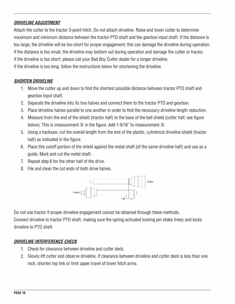
4. Measure from the end of the shield (tractor half) to the base of the bell shield (cutter half; see figure
below). This is measurement ‘A’ in the figure. Add 1-9/16˝ to measurement ‘A’.
5. Using a hacksaw, cut the overall length from the end of the plastic, cylindrical driveline shield (tractor
half) as indicated in the figure.
6. Place this cutoff portion of the shield against the metal shaft (of the same driveline half) and use as a
guide. Mark and cut the metal shaft.
7. Repeat step 6 for the other half of the drive.
8. File and clean the cut ends of both drive halves.
Do not use tractor if proper driveline engagement cannot be obtained through these methods.
Connect driveline to tractor PTO shaft, making sure the spring-activated locking pin slides freely and locks
driveline to PTO shaft.
DRIVELINE INTERFERENCE CHECK
1. Check for clearance between driveline and cutter deck.
2. Slowly lift cutter and observe driveline. If clearance between driveline and cutter deck is less than one
inch, shorten top link or limit upper travel of lower hitch arms.
PAGE 11
CUTTING HEIGHT ADJUSTMENT
WARNING ■ Keep all persons away from operator control area while performing adjustments, service, or
maintenance.
■ Avoid low cutting heights when at all possible. Striking the ground with a cutter blade during
operation results in one of the most damaging shock loads a cutter can encounter. Repeated blade/
ground contact will cause damage to the cutter and drive.
1. Level cutter from side to side. Check by measuring from cutter frame to the ground on both sides.
2. Adjust, using tractor 3-point arm leveling device.
3. Control cutting height with tractor 3-point arms and the rear tail-wheel adjustment.
4. To raise rear of cutter, move tail-wheel arm downward.
5. To raise front of cutter, raise tractor 3-point arms.
The cutting height is the distance between the blade and the ground. The blades on your cutter are
approximately 5˝ below the deck; your deck is 7˝ tall. If, for instance, you would like a 3˝ cut, raise the cutter
until its deck is 8˝ above the ground; if you would like a 4˝ cut, raise the cutter until its deck is 9˝ above the
ground, and so on. For best cutting results, the front of the cutter should be slightly lower than the rear. The
rear of the cutter should be approximately 1/2˝ to 3/4˝ higher than the front.
OPERATING TECHNIQUE
■ The operating power for the cutter is provided by the tractor’s PTO. Operate the PTO at 540 RPM
(never exceed). Know how to stop the tractor and cutter quickly and safely in the event of an
emergency.
■ Engage the PTO at a low engine RPM. Engagement of the PTO at high engine RPM places the
driveshaft and gearbox under large stresses. After the PTO is engaged, raise PTO speed to 540 RPM.
Maintain this PTO speed throughout the cutting operation.
■ Gearbox protection is provided by way of a slip-clutch or shear-bolt (depending upon model). This
allows the driveline to either ‘slip’ or shear a bolt under excessive torsion loads. It is in this manner that
the gearbox is isolated from potentially damaging shocks. Under abnormal torque loads, both models
also provide protection to the driveline itself. Slip-clutches require service to keep them fully functional.
A neglected slip-clutch is akin to having no protection at all as they can lose their ability to slip. Always
use SAE grade 2 bolts for shear-bolt models. Do not use bolts of a higher grade. These bolts are
significantly stronger than grade 2 and will transfer damaging shocks to the gearbox and driveline by
failing to shear when necessary.
PAGE 12
■ Move slowly into material. Adjust tractor ground speed to provide a clean cut without lugging the
tractor engine. Proper ground speed will depend on the terrain and the material’s height, type, density,
and moisture content. The operator will be able to determine appropriate ground speeds for different
conditions. Normal ground speed ranges from between 2 and 5 mph.
■ Under certain conditions, the tractor tires may push the grass down. This can result in an uneven cut.
When this occurs, reduce your ground speed, but maintain the PTO at 540 RPM. Lowering your travel
speed will allow the grass more time to rebound.
STORAGE
WARNING ■ Disconnect cutter driveshaft and secure up off the ground. Raise cutter with 3-point hitch. Place
blocks under cutter skirt. Slowly lower the cutter onto the blocks. Disconnect the cutter from the
tractor 3-point hitch and carefully drive tractor away from cutter.
■ Before leaving the area, check to ensure the cutter is stable.
■ Keep children and bystanders away from the storage area.
PRE-OPERATION CHECKLIST
OWNER/OPERATORS RESPONSIBILITY!
■ Review and follow all safety rules ([pages 5-7]) and machine safety decals.
■ Ensure the equipment is properly and securely attached to the tractor.
■ Make sure driveline spring-operated locking pin slides freely and is seated firmly in tractor PTO spline
groove.
■ Lubricate all grease fitting locations. Make sure PTO shaft slip joint is lubricated.
■ Check to be sure gear lube runs out the small check plug on the side of the gearbox.
■ Check that all hardware is properly installed and secured.
■ Check that blades are sharp, secure, free of cracks, and that the cutting edge is positioned to lead in a
counterclockwise rotation (as viewed from the top of the unit).
■ If using shields or guards, check that they are properly installed and in good condition. Replace if
damaged.
■ Check cutting height, front-to-rear attitude, and top link adjustment.
■ Place tractor PTO and transmission in neutral before starting engine.
■ Inspect area to be cut and remove stones, branches, or other hard objects that may be thrown and
cause injury or damage.

PAGE 13
OWNER SERVICE
The information in this section is written for operators who possess basic mechanical skills. If you need
help, your dealer has trained service technicians available. For your protection, read and follow the safety
information in this manual.
WARNING ■ Keep all persons away from operator control are while performing adjustments, service, or
maintenance.
CAUTION ■ If you do not understand any part of this manual and need assistance, see your dealer.
■ Always wear relatively tight and belted clothing to avoid getting caught in moving parts. Wear sturdy,
rough-soled work shoes and protective equipment for eyes, hair, hands, hearing and head.
BLOCKING METHOD
WARNING ■ Before performing any service or maintenance, disconnect driveline from tractor PTO.
■ Never go underneath equipment (lowered to the ground or raised) unless it is properly blocked
and secured. Never place any body part underneath equipment or between moveable parts even
when the engine has been turned off. Hydraulic system leak down, hydraulic system failures,
mechanical failures, or movement of control levers can cause equipment to drop or rotate
unexpectedly and cause severe injury or death. Follow Operator’s Manual instructions for working
underneath and blocking requirements or have work done by a qualified dealer.
To minimize the potential hazards of working underneath the cutter, follow these procedures.
1. Jack stands (4) with a load rating of at least 1000 lbs. are the only approved blocking device for this
cutter. Install a minimum of four jack stands under each corner of the cutter before working underneath
the unit. Do not position jack stands under wheels, axles, or wheel supports. Components can rotate
and cause the cutter to fall.
2. Consider (and check) the overall stability of the blocked unit before working underneath. The working
surface must be level and solid to properly support the jack stands while they are supporting the cutter.
Make sure the cutter is approximately level.

PAGE 14
3. With full cutter weight lowered onto jack stands, test the blocking stability carefully, but vigorously, to
ensure its stability.
4. If cutter is attached to tractor when blocking, set the brakes, remove the key, and block the cutter
before working underneath. Also, securely chock the rear tractor wheels (both in front and behind) and
tighten the tractor’s lower 3-point arm anti-sway mechanism to prevent side-to-side movement.
LUBRICATION
1. Do not allow excess grease to collect on or around parts, particularly when operating in sandy areas.
2. See figures below for lubrication points and frequency of lubrication based on normal operating
conditions. Severe or unusual conditions may require more frequent lubrication.
3. Use a lithium grease of #2 consistency with a MOLY (molybdenum disulfide) additive for all locations
unless otherwise noted. Be sure to clean fittings thoroughly before attaching grease gun. One good
pump from most guns is sufficient when the lubrication schedule is followed.
4. Equipment is shipped without gear oil in the gearbox. Your gearbox needs 32 oz. of SAE gear oil; 75W-
90 is recommended for ambient temperatures of -5F to 60F, 85W-140 is recommended for ambient
temperatures of 40 F to 120 F. The oil level will be at the same level as the horizontal input shaft when
filled properly. The gearbox has a side plug that is designed to allow for oil level checks. If oil runs out
of the hole when the plug is removed, the oil level is sufficient.
PAGE 15
LUBRICATION POINTS
1. Tail-wheel pivot tube ....................................................................8 hours
2. Tail-wheel .....................................................................................8 hours
3. PTO shaft: front and rear U-joints ...............................................8 hours
4. PTO shaft: slip joint (apply grease to inner shaft .........................8 hours
5. PTO shaft: plastic shield bearings ...............................................8 hours
6. Gearbox (check oil) ......................................................................Daily
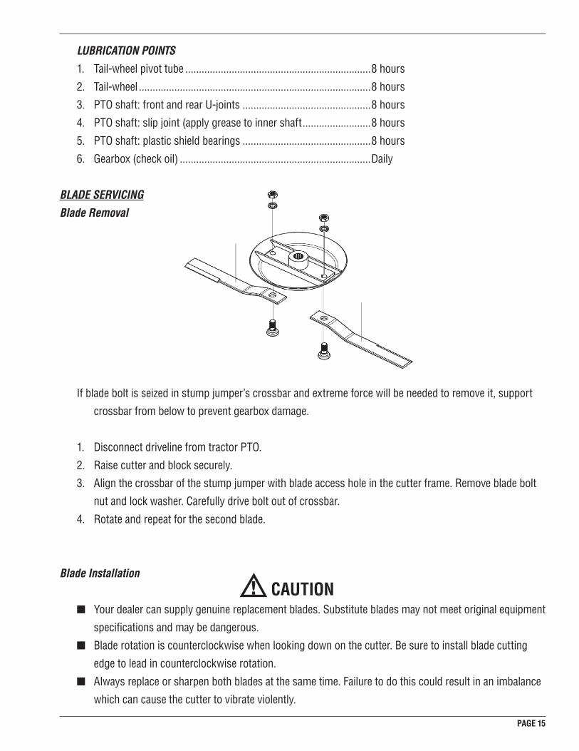
BLADE SERVICING
Blade Removal
If blade bolt is seized in stump jumper’s crossbar and extreme force will be needed to remove it, support
crossbar from below to prevent gearbox damage.
1. Disconnect driveline from tractor PTO.
2. Raise cutter and block securely.
3. Align the crossbar of the stump jumper with blade access hole in the cutter frame. Remove blade bolt
nut and lock washer. Carefully drive bolt out of crossbar.
4. Rotate and repeat for the second blade.
Blade Installation
CAUTION ■ Your dealer can supply genuine replacement blades. Substitute blades may not meet original equipment
specifications and may be dangerous.
■ Blade rotation is counterclockwise when looking down on the cutter. Be sure to install blade cutting
edge to lead in counterclockwise rotation.
■ Always replace or sharpen both blades at the same time. Failure to do this could result in an imbalance
which can cause the cutter to vibrate violently.

PAGE 16
1. Inspect the blade bolts for nicks or gouges and, if found, replace the damaged blade bolt(s).
2. Insert blade bolt through the blade. Blade should swivel on blade bolt; if it doesn’t, determine the cause
and correct.
3. Align crossbar with blade access hole in cutter frame. Apply a liberal coating of an anti-seize product to
the blade bolt and crossbar hole. Make sure blade offset is away from cutter. Push blade bolt through
crossbar.
4. Insert lock washer and nut through blade access hole in the cutter deck. Install on blade bolt and
tighten to 450 ft-lbs using a 1-11/16˝ socket.
Blade Sharpening
■ Closely inspect blades for cracks or nicks. If damage is found, replace blades in pairs.
■ When sharpening blades, grind the same amount on each blade to maintain balance. Replace blades in
pairs. Unbalanced blades will cause excessive vibration, which can damage gearbox bearings.
1. Sharpen both blades at the same time to maintain balance. Follow original sharpening pattern.
2. Do no sharpen blade to a razor edge: leave at least a 1/16˝ blunt edge.
3. Do not sharpen back side of blade.
SLIP-CLUTCH ADJUSTMENT
The slip-clutch (if equipped) is designed to slip so that the gearbox and the driveline are protected if the cutter
blades strike an obstruction.
A new slip clutch or one that has been in storage over the winter may seize, rendering the shaft and gearbox
completely unprotected. Before operating the cutter, make sure it will slip by performing the following
operation:
1. Turn off tractor and remove key.
2. Loosen nuts on springs until the springs can rotate freely, yet remain secure on the bolts.
3. Make in-line marks on the outer plates of the slip-clutch.
4. Securely attach cutter to the tractor and start the tractor.
5. Engage the PTO for several seconds then quickly disengage it.
6. Turn tractor off and remove key.
7. The friction plates should have “slipped.” If the marks made previously are no longer in-line with each
other, this is the case.
8. If the clutch does not slip, check assembly for oil, grease, and debris.
9. Reassemble clutch and tighten bolts no more than 1/8 of a turn at a time until the desired setting of
1.15˝ spring length is reached.
10. If excessive slippage continues, check lining plates for excessive wear. The slip plates are 1/8˝ thick
when new; they should be replaced after 1/32˝ of wear to ensure proper operation.

PAGE 17
DRIVELINE SHEAR-BOLT REPLACEMENT
■ Always use a 1/2˝ x 3-1/4˝ SAE grade 2 bolt as a replacement part. Using a hardened bolt (such as
grade 5 or grade 8) may result in damage to driveline or gearbox.
1. Slide the driveline bell shield (covers the U-joint of the PTO shaft and input shaft of gearbox) back along
the driveline guard. This is accomplished by depressing the 3 tabs (just inside the holes provided) at
the base of the bell and sliding the bell shield back over the cylindrical guard.
2. Remove the damaged shear bolt.
3. Rotate the driveline to align the holes in the yoke with the hole in the input shaft of the gearbox. Install
shear bolt and secure with nylock nut.
4. Ensure that the retaining ring is set properly in the groove on the input shaft of the gearbox.
5. Slide the bell shield back over the three tabs at its base, ensuring that the tabs snap back into position.
SHIELDING REPAIR
DANGER ■ This machine is equipped with front and rear guards.
■ DO NOT operate the machine without the guards in place.
Rubber Shielding
Inspect rubber shielding each day of operation and replace if bent, cracked or broken.
Chain Shielding
Inspect chain shielding each day of operation and replace any broken or missing chains as required.
CLEANING
After Each Use
■ Remove large debris (clumps of dirt, grass, crop residue, etc.) from machine.
■ Inspect machine and replace worn or damaged parts.
■ Replace any missing, damaged, or otherwise unreadable safety decals.
Periodically or Before Extended Storage
■ Clean large debris (clumps of dirt, grass, crop residue, etc.) from machine.
■ Remove the remainder using a low-pressure water spray.
1. Take extra care when spraying near safety decals. The water spray could penetrate under the
decal and peel it off.
2. Be careful when spraying near any paint damage. The spray could remove more paint.

PAGE 18
■ Inspect the cutter and replace any worn or damaged parts. After an extended period of non-use,
any damage to the cutter may be overlooked, or forgotten, when the machine is again put into
service.
■ Sand down scratches and the edges of areas of missing paint and coat with Bad Boy touch-up
paint.
■ Replace any missing, damaged, or otherwise unreadable decals.
TROUBLESHOOTING
PROBLEM POSSIBLE CAUSE SOLUTION
Grass is cut lower in the center of the path than at the edge.
Height of cutter is too low at rear or front.
Adjust cutter height and attitude so that cutter rear and front are within ½˝ of same height.
Streaking conditions in path. Conditions too wet for mowing.
Blades unable to cut grass pressed flat by tractor tires.
Dull Blades
Allow grass to dry before mowing.
Slow ground speed of tractor but keep PTO running at 540 RPM.
Sharpen or replace blades. Material discharges from cutter unevenly; material bunches along path.
Material too high and dense.
Grass wet.
Rear of cutter too low, trapping material under cutter.
Reduce ground speed (maintaining 540 RPM tractor PTO) or make two passes. Raise cutter for the first pass; then lower cutter to desired height and cut perpendicular to the first passes.
Allow grass to dry before mowing.
Adjust cutter height and attitude.
Cutter no longer cuts at all (Shear bolt model).
Shear-bolt has sheared. Install new shear-bolt.
Cutter will not cut all the time (Slip-clutch model).
Slip-clutch excessively slipping. Adjust slip-clutch according to instructions under ‘SLIP-CLUTCH ADJUSTMENT’ section of this manual.

PAGE 19
CUTTER ASSEMBLY AND PART LIST

PAGE 20

PAGE 21
ASSEMBLY INSTRUCTIONS
Note: Use cutter part list and accompanying illustration located in the previous section to reference item
numbers indicated in the assembly instructions. Item numbers are in parenthesis. Partial or full assembly of
the cutter may have been performed prior to purchase.
1. Attach Front Hitch Braces (4) to the hitch points located at the front of 5´ Cutter Deck Assembly (1)
with Category 1 Lift Pins (25). The braces should be on the inside of the hitch points; the lift pins on
the outside. Do not tighten.
2. Insert 5/8˝ x 6˝ Hex Bolt (12) through the following parts in the order given: 5/8˝ Flat Washer (19); Front
Hitch Brace (4); Middle Brace (3); Hinge Spacer (6) {At this point, slide Hinge Spacer through the larger
holes of Hinge Bracket (5)}; Middle Brace (3); Front Hitch Brace (4); 5/8˝ Flat Washer (19). Secure with
5/8˝ Nylock Nut (16). Do not tighten.
3. Insert 5/8˝ x 2-1/2˝ Hex Bolt (9) through the following parts in the order given: from the outside-in, the
rearward, left 5/8˝ hole in the ‘H’ frame of 5˝ Cutter Deck Assembly (1); 5/8˝ ID 1/4˝ Thick Nylon Spacer
(22); 5/8˝ hole in Rear A-Arm Assembly (2); Middle Brace (3). Secure with 5/8˝ Nylock Nut (16). Do not
tighten. Repeat step #3 for the right side.
4. Attach Height Adjustable Plate (7) by way of the two 1/2˝ holes at the rear of 5´ Cutter Deck Assembly
(1) using two 1/2˝ x 1-1/4˝ Hex Bolts (10) and two 1/2˝ Nylock Nuts (17). The bolts should pass
through the flat portion of Height Adjustable Plate, 1/2˝ holes of 5´ Cutter Deck Assembly, and secured
underneath the deck with the 1/2˝ Nylock Nuts. The curvature of the Height Adjustable Plate should
‘point’ forward with respect to the 5´ Cutter Deck Assembly. The Height Adjustable Plate should also
be forward of the cross brace on Rear A-Arm Assembly (2). Tighten to 70 ft-lbs as indicated in the
Fastener Torque Chart.
5. Attach Rear A-Arm Assembly (2) to Height Adjustable Plate (7) using two 1/2˝ x 1-1/4˝ Hex Bolts (10)
and two 1/2˝ Nylock Nuts (17). The bolts should pass through the two holes on the cross brace of
Rear A-Arm Assembly, the top two holes on the curved section of Height Adjustable Plate, and secured
with the two 1/2˝ Nylock Nuts. {When cutter is placed into service, any of the four hole pairs on
Height Adjustable Plate may be utilized for cut height selection.} Tighten to 70 ft-lbs as indicated in the
Fastener Torque Chart.
6. Insert post of the Tail Wheel Assembly (8) through the following parts in the order given: tube on Rear
A-Arm Assembly (2) {entering from the bottom of the tube}; 1-1/4” Flat Washer (20). Secure by
inserting the parallel dowel pin through hole in post of the Tail Wheel Assembly.

PAGE 22
GUARD ASSEMBLIES
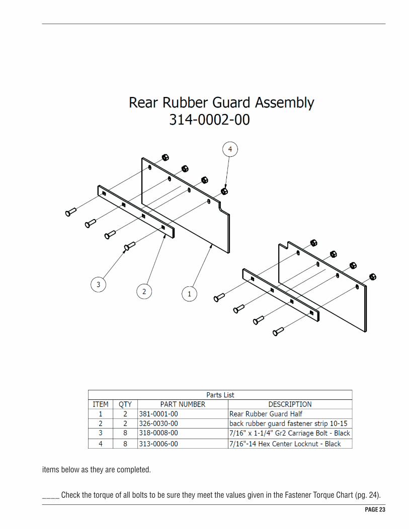
PAGE 23
FASTENER TORQUE CHARTNOTICE: Torque values given in the above text assume an unlubricated fastener. If using a lubricated fastener,
reduce the torque (given in the previous text) by 25%.
Fastener Item Number Torque(Lubricated/Unlubricated)
⅝5/8˝ x 2-1/2˝ Hex Bolt 9 56 ft-lbs / 75 ft-lbs
1/2˝ x 1-1/4˝ Hex Bolt 10 52 ft-lbs / 70 ft-lbs
⅝5/8˝ x 6˝ Hex Bolt 12 90 ft-lbs / 120 ft-lbs
1/2˝ x 3-1/4˝ Hex Bolt (Shear-bolt)
13 30 ft-lbs / 40 ft-lbs
⅝5/8˝x 1-1/2˝ Hex Bolt 14 150 ft-lbs / 200 ft-lbs
1-1/8˝ Blade Bolt 32 337 ft-lbs / 450 ft-lbs
DEALER’S CHECKLISTS
PRE-DELIVERY CHECK LIST
■ IMPORTANT- The gearbox was not filled with gear oil at the factory. It must be filled before the cutter
can be placed into service (see Lubrication, pg. 14). Failure to fill the gearbox with the proper quantity
of gear oil will result in damage to the gearbox.
It is the dealer’s responsibility to fully assemble and inspect the cutter before the customer takes delivery of
the unit. The following check list is provided as a memory aid to ensure all points are inspected. Check off the
items below as they are completed.
____ Check the torque of all bolts to be sure they meet the values given in the Fastener Torque Chart (pg. 24).

PAGE 24
____ Check that both cotter pins are properly secured.
____ Check the PTO shaft for proper installation.
____ Check that the gearbox is properly filled with gear oil and that no seals are leaking.
____ Grease all lubrication points as shown in Lubrication (pgs. 14-15).
____ Check that blades have been properly installed. The cutting edge should lead in a counterclockwise
motion when viewed from above.
DELIVERY CHECKLIST
____ Explain the importance of periodic inspections and lubrication to the customer.
____ Present the Owner’s Manual to the customer and request that the customer and all other users read the
material before operation. Explain the importance of the safety rules.
____ Explain the importance of front ballasts. This unit weighs 650 pounds; the customer needs to weigh the
tractor and equipment to ensure at least 20% of the total weight is on the tractor’s front wheels.
____ Explain that if the unit is transported on or along a roadway, safety devices (such as reflector decals)
should be utilized in order to alert motorists of the equipment’s presence.

PAGE 25
PAGE 26
WARRANTY
OWNER/OPERATOR’S RESPONSIBILITYIt is the owner and/or operator’s responsibility to read the owner’s manual before use. Failure to read the
owner’s manual is considered a misuse of this equipment.
It is the owner and/or operator’s responsibility to inspect the product and to have any part(s) repaired or
replaced before continued operation. Failure to do so could cause damage, excessive wear to other parts, or
jeopardize operator safety.
Bad Boy Cutters will not be responsible for the pickup and
delivery of a machine for warranty purposes or inspection.
LIMITED WARRANTY
Bad Boy Cutters warrants to the original purchaser of any new Bad Boy Cutter(s) that the equipment be free from
defects in material and workmanship for a period of two (2) year from date of retail sale.
At Bad Boy Cutters request, the customer will make the defective part available for inspection by Bad Boy Cutters
and/or return the defective part to Bad Boy Cutters. Transportation charges prepaid.
WHAT THIS WARRANTY DOES NOT COVER:
This warranty does not cover defects caused by depreciation or damage caused by wear, accidents, improper
maintenance, improper use or abuse of the product, alterations, or failure to follow the instruction contained in
the Owner’s Manual for operation and maintenance.
Normal maintenance service and normal replacement items such as gearbox lubricant, worn blades, tire, or
normal deterioration of exterior finish due to use or exposure.
The customer shall pay any charges for making service calls and/or for transporting the Cutter to and from the
place where the inspection and/or warranty work is performed.
Bad Boy Cutters will not be responsible for the pickup and delivery
of a machine for warranty purposes or inspection.

PAGE 27
WARRANTY LIMITATION:
THERE IS NO OTHER EXPRESS WARRANTY. ANY WARRANTY THAT MAY BE IMPLIED FROM THIS
PURCHASE INCLUDING MERCHANTABILITY AND FITNESS FOR A PARTICULAR PURPOSE IS HEREBY
LIMITED TO THE DURATION OF THIS WARRANTY AND TO THE EXTENT PERMITTED BY LAW ANY AND
ALL IMPLIED WARRANTIES ARE EXCLUDED. Some states do not allow limitations on how long an implied
warranty lasts, so the above limitations may not apply to you.
BAD BOY CUTTERS WILL NOT BE LIABLE FOR ANY INCIDENTAL, CONSEQUENTIAL, OR SPECIAL
DAMAGES AND/OR EXPENSES IN CONNECTION WITH THE PURCHASE OR USE OF THE CUTTER.
Some states do not allow the exclusion or limitation of incidental or consequential damages, so the above
limitation(s) or exclusion(s) may not apply to you.HOW TO OBTAIN SERVICE UNDER THIS WARRANTY:
Warranty service can be arranged by contacting the dealer where you purchased the mower or by contacting Bad
Boy Cutters at [email protected].
Proof of the date of purchase may be required to verify warranty coverage.
B. Warranty claims will not be reviewed or paid unless the warranty registration is received by Bad Boy Cutters within 30 days of the retail purchase date.
Record the model number, serial number and date purchased. This information will be helpful obtaining parts or
service if required.
SERIAL NUMBER _____________________________
DATE OF RETAIL SALE _________________________
PLACE OF PURCHASE _________________________
MAKE CERTAIN THE WARRANTY REGISTRATION HAS BEEN FILED WITHIN 30 DAYS FROM THE DATE OF
PURCHASE BY E-MAILING THE FOLLOWING TO:
NAME, ADDRESS, PHONE NUMBER, DATE, AND PLACE OF PURCHASE

PAGE 28
102 Industrial Drive
Batesville, Arkansas 72501
(870) 698-0090